Table of Contents
Advertisement
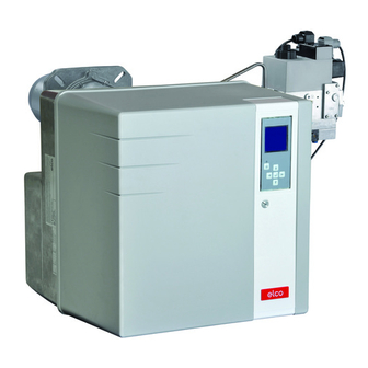
VG4.460 DP
VG4.610 DP
Operating instructions
For specialist installation engineers
Gas burners ........................................... 2-28
de, fr..................................... 4200 1032 7000
it, nl ...................................... 4200 1032 7100
............................................. 4200 1032 6900
03/2013 - Art. Nr. 4200 1032 7200A
en
Advertisement
Table of Contents

Subscribe to Our Youtube Channel
Related Manuals for elco VG4.610 DP


Summary of Contents for elco VG4.610 DP
- Page 1 VG4.460 DP VG4.610 DP Operating instructions For specialist installation engineers Gas burners ........... 2-28 de, fr........4200 1032 7000 it, nl ........4200 1032 7100 ..........4200 1032 6900 03/2013 - Art. Nr. 4200 1032 7200A...
-
Page 2: Table Of Contents
2009/142/EC Gas appliances Important information The following standards should be directive VG4.460 DP and VG4.610 DP burners are observed in order to ensure safe, designed for the low-pollutant combustion environmentally sound and energy- 2004/108/EC EMC directive of natural gas and propane gas. The... -
Page 3: Burner Description
Overview Burner description Control and safety unit Display Air pressure switch Auxiliary motor supply relay Blower motor Igniter Y10 Air flap servomotor Adjusting screw for dimension Y Housing Plate hanging device (Maintenance) Combustion chamber pressure take-off pipe Burner tube 7-pin connector 10.1 4 pin connector 10.2 3-pin connector (auxiliary motor supply relay) -
Page 4: Operation, Safety Operation
Operation Safety function Description of the function Safety functions A pre-ventilation time of 24 seconds - If no flame is produced when the burner is started (gas release), the begins when first powering up, after a burner is switched off at the end of the power cut or a lockout, after the gas safety time which lasts no more than supply has been cut or after a shutdown... - Page 5 Operation TCG 5xx control unit The TCG 5xx control and safety unit Locking and unlocking controls and monitors the forced draught The control unit can be locked (switched burner. The microprocessor-controlled to malfunction mode) by pressing the program sequence ensures maximum unlocking button and unlocked (fault stability of time periods, regardless of...
- Page 6 These are pre-set in the factory. No modifications may be carried out on-site without prior consultation with ELCO. • menu for statistical data The access code and the setting setpoints for these menus are available on request. 03/2013 - Art. Nr. 4200 1032 7200A...
- Page 7 Operation TCG 5xx control unit Operating cycle phases: 13:Closing of the air flap until the 1: No voltage minimum regulation position is 2: Powering up, no heat request reached 3: Heating request 14:Operation at intermediate regulation 4: Opening an air flap, arrival in pre- power ventilation position 15:Operation at minimum regulation...
-
Page 8: Terminal Allocation Chart
Operation Terminal allocation chart 230 Volt connection Control thermostat Heating L1 power Solenoid valve Earth Burner motor Earth Igniter request supply Connector Terminal Flame check Remote Air pressure Fault Gas pressure unlocking switch display switch Connector Terminal Terminal Description Connector Terminal Description Connector... - Page 9 Operation Terminal allocation chart Low voltage connections Display-PC interface Terminal Connector Connector Terminal Air servomotor Terminal Description Connector Terminal Description Connector not used not used not used not used not used not used not used not used not used not used not used not used not used...
-
Page 10: Mb-Vefgas Train
Operation MB-VEF gas train Electrical connection of solenoid valves (DIN 43650) Electrical connection of the gas pressure switch (DIN 43650) Gas pressure switch Inlet flange Pressure measuring nipple R1/8, upstream of filter (option) Filter (under the cover) Connection for furnace pressure release pipe pF, R1/8 Adjusting screw for V ratio Adjusting screw for zero point... -
Page 11: Burner Assembly, Gas Train Assembly
Assembly Burner assembly Preparing the boiler front Burner head assembly • Prepare the burner mounting plate/ • Screw the bolts into the burner fixing boiler door in accordance with the plate/boiler door and position the diagram. insulation material. For a drill hole of •... - Page 12 Assembly Gas manifold Pressure take-off pipes Gas train assembly • Check the correct position of the O-ring B in the gas connecting flange • Secure the gas train on the burner head so that the gas train coils are in the upper vertical position.
-
Page 13: Checking The Combustion Components
Assembly Checking/adjusting the burner head Checking the burner head • Check the adjustment settings of the ionisation probe and of the ignition electrode as per the diagrams. Setting to liquid gas operation • Remove the gas diffuser 5 and the turbulator 2. -
Page 14: Electrical/Gas Connection
Assembly Gas connection Electrical connection Checks before commissioning General regulations applying to the specified by the draft combustion gas connection ordinance. • The gas train must only be connected It is the responsibility of the fitter or his to the gas mains by a recognised representative to obtain approval for the specialist. -
Page 15: Adjustment Data
Commissioning Adjustment data Furnace Dimension Burner Gas valve setting pressure Air flap setting power Screw V / Screw N (mm) (mbar) MB-VEF420 MB-VEF412 MB-VEF407 Mini. Maxi. Ignition Mini. Maxi. 100 200 1,2 / 0 1,4 / 0 1,2 / 0 1,7 / -0,5 1,7 / 0 1,5 / 0... -
Page 16: Air Regulation
Commissioning Air regulation Gas valve adjustment Air regulation The regulation of air in the burner head Combustion air is regulated at two affects not only the air flow but also the points: mixing zone and the air pressure in the •... -
Page 17: Pre-Adjustment Without Flame
Commissioning Pre-setting without flame Setting is carried out in 2 phases: Important - pre-adjustment without flame At this point, no setting position for the - setting the flame, to fine tune the servomotor has been defined, therefore settings based on the combustion the burner cannot be started under results these conditions. - Page 18 Commissioning Pre-setting without flame General advice before starting the burner End of presetting menu without flame When all the positions of the servomotor have been determined according to the required settings, it is then possible to move on to the next section for commissioning - "Setting the flame". To do this, place the cursor in the lower part of the screen on the symbol and confirm by pressing the...
-
Page 19: Setting The Flame
Commissioning Setting the flame - If the boiler heating request The air flap switches to the is not present, the boiler ignition/pre-ignition position. remains on standby. In this case, it is still possible to return to the previous setting menu "Pre-setting without flame". - Page 20 Commissioning Setting the flame Setting the minimum pressure If the flame has been detected and stabilised, the control unit sets the burner to minimum power as soon as it receives the regulation authorisation. - Check the combustion values (CO, CO , soot test).
- Page 21 Commissioning Setting the flame Operating mode Closing the "Setting the flame" menu The burner setting is now complete. If necessary, it is possible to again correct each of the settings values. To do this, position the cursor on the value to be modified, using the key.
-
Page 22: Saving The Adjustment Values In The Display
Commissioning Setting the gas pressure switch Setting the air pressure switch Saving the adjustment values in the display Setting the gas pressure switch • Turn the dial clockwise until the gas • To set the switch-off pressure: remove pressure switch shuts down the the cover from the gas pressure burner. -
Page 23: Maintenance
Servicing Maintenance Burner and boiler servicing must only Work recommended as part of annual - Flame monitor and automatic be carried out by a professional burner maintenance: combustion control unit function check heating engineer trained in these - Burner test run, input measurement in - Commissioning the burner operations. -
Page 24: Servicing Maintenance
Servicing Maintenance Replacing the flame tube For this operation, it is necessary to Precautions either open the furnace gate or remove After any operation: check the the burner. combustion performance under real - Variant 1 - Access via the furnace gate operating conditions (doors shut, •... -
Page 25: Troubleshooting
Servicing Troubleshooting Malfunction diagnosis and repair number. In the event of a malfunction, first check Only use original spare parts. that the prerequisites for correct Switch off the power supply operation are fulfilled: before carrying out 1. Is there any current? maintenance or cleaning. - Page 26 Servicing Troubleshooting Symbol Observation Cause Corrective action Burner blower starts up. Air pressure switch: Contact does Readjust the pressure switch. Burner does not start. not close. Check the wiring. Replace the pressure switch. Burner blower starts up. Flaring during pre-ventilation or Check the valve.
-
Page 27: Fault Diagnosis Menu Operating Statistics Menu
Servicing Fault diagnosis menu Operating statistics menu Fault diagnosis menu To access the fault diagnosis menu, press any key when the burner is ready to operate, when the burner is in operation, or when it is in malfunction mode. It is not possible to access the fault diagnosis menu during the start-up phase. -
Page 28: Operating Statistics Menu
Servicing Operating statistics menu - Total number of burner start-ups since the last meter reset - Total number of faults since the last meter reset - Total operating time since the last meter reset - Total number of operating hours at rated output since the last meter reset - Number of "unwanted flame"... - Page 29 03/2013 - Art. Nr. 4200 1032 7200A...
- Page 30 03/2013 - Art. Nr. 4200 1032 7200A...
- Page 31 03/2013 - Art. Nr. 4200 1032 7200A...
- Page 32 Hotline ELCO Austria GmbH +43 (0)810- Aredstr.16-18 400010 2544 Leobersdorf ELCO Belgium n.v./s.a. +32 (0)2- Industrielaan 61 4631902 1070 Anderlecht ELCOTHERM AG +41 (0)848 808 Sarganserstrasse 100 7324 Vilters ELCO GmbH +49 (0)180- Dreieichstr.10 3526180 64546 Mörfelden-Walldorf ELCO Italia S.p.A.
Need help?
Do you have a question about the VG4.610 DP and is the answer not in the manual?
Questions and answers