Table of Contents
Advertisement
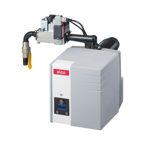
VECTRON G 1.40
VECTRON G 1.55
VECTRON G 1.85
Bedieningshandleiding
Voor de gespecialiseerde vakman
Aangeblazen gasbrander...................... 2-17
Operating instructions
For specialist installation engineers
Gas burners ......................................... 18-33
de, fr, it................................. 4200 1015 8200
............................................. 4200 1016 3800
01/2009 - Art. Nr. 4200 1016 3900A
nl
en
Advertisement
Table of Contents

Related Manuals for elco VECTRON G 1.40


Summary of Contents for elco VECTRON G 1.40
- Page 1 VECTRON G 1.40 VECTRON G 1.55 VECTRON G 1.85 Bedieningshandleiding Voor de gespecialiseerde vakman Aangeblazen gasbrander...... 2-17 Operating instructions For specialist installation engineers Gas burners ......... 18-33 de, fr, it......... 4200 1015 8200 ..........4200 1016 3800 01/2009 - Art. Nr. 4200 1016 3900A...
-
Page 2: Table Of Contents
We can accept no warranty liability ELCO. Assembly and commissioning whatsoever for loss, damage or injury must be carried out only by authorised EN 60335-2 caused by any of the following:... -
Page 3: Burner Description
Overview Burner description Control and safety unit Display Ionisation bridge Air pressure switch Sealing washer for Liquefied Petroleum Gas Electric motor Air pressure nipple Ignition transformer Gas train connecting flange Fastening screws for equipment plate Securing device (service) Housing Electrical connection (covered) Release knob Gas head adjusting screw Cover... -
Page 4: Gas Train Vr4625 / Mb-Dle407
Function Gas train VR4625 / MB-DLE 407 The compact unit VR4625 with VR4625 integrated gas pressure regulation is suitable for the operation of single-stage forced-draught gas burners. The compact gas train is registered under the no.: CE-0063AP3090 Technical specifications Inlet pressure 15-60 mbar Ambient temperature 0 to +60 °C... -
Page 5: Automatic Combustion Control Unit
Function Automatic control unit TCG 1xx The TCG 1xx automatic gas combustion Pressing and ... leads to ... control unit controls and monitors the forced- holding the R draught burner. The microprocessor- button for ... controlled programme sequence ensures maximum stability of time periods, regardless …... -
Page 6: Allocation Chart Connection Socket
Function Allocation chart Connection socket Remote Air pressure Flame monitor Gas pressostat L1 power supply Earth unlocking switch Connector Terminal Earth Solenoid valve Burner motor Firing Malfunction light Connecto r no. Terminal Terminal Designation Connector no. Terminal Designation Connector no. Flame monitor signal Ignition transformer phase Neutral... -
Page 7: Operation, Safety Functions
Function Operating function Safety function Description of functions from the sensor to the burner tip. The - Gas solenoid valves close When the system is switched on for the ionisation current must be at least 8 µA. - Flame goes out first time, after a power failure or safety - Blower motor runs on (14 sec) Safety functions... -
Page 8: Burner Assembly, Burner Installation Position
Assembly Burner assembly Burner installation position Gas connection, installation location Burner assembly combustion chamber. The burner flange 3 is equipped with Installation: elongated holes and can be used with a • Secure connecting flange 3 to the hole circle diameter of 150 - 170 mm. boiler using screws 4 These dimensions comply with EN 226. -
Page 9: Liquefied Petroleum Gas, Electrical Connection
Assembly Liquefied Petroleum Gas operation Electrical connection Setting the ionisation probe and ignition electrode See diagram Diagram 1: Standard setting Diagram 2: Burner head setting for older heating boilers with tendency toward CO emissions • Fit the two plates C between baffle plate A and natural gas shutter D. -
Page 10: Checks Before Commissioning
Start up Checks before start-up Ionisation current measurement Checks before start-up Burner program sequence test Before commissioning the burner, the without flame formation following checks and inspections are to The burner control unit activates the first be carried out time the sealing test is activated. Gas pressure is required for this. -
Page 11: Adjustment Data Air Regulation
Start up Adjustment data Air regulation B u r n e r B u r n e r A ir fla p h e a d Ga s B u r n e r T yp e h e a d g a s D im e n s io n A ir in ta k e p o s itio n... -
Page 12: Setting The Vr4625 Compact Gas Unit
Start up Setting the VR4625 compact gas unit Setting the compact gas unit Example: Loosen screw plugs at measuring points To set a power of 25 kW with a G1.40, 119 and 119 pBr and connect apply the following settings: measuring devices. -
Page 13: Setting The Mb-Dle407 Compact Gas Unit
Start up Setting the MB-DLE407 compact gas unit Pressure controller setting Initial load flow adjustment - rapid The adjusting screw has a path of 60 stroke adjustment turns for adjusting the output pressure. • Twist off protective cap 5 and turn it Three turns clockwise or anti-clockwise through 180°... -
Page 14: Setting The Air Pressure Switch
Start up Air pressure switch adjustment Setting the gas pressostat Operating check Setting the gas pressostat • Turn the dial clockwise until the gas • To set the shut-off pressure: Remove pressostat shuts down the burner. the cover of the gas pressostat. •... -
Page 15: Maintenance
Service Maintenance Burner and boiler servicing must only Checking the exhaust gas be carried out by a trained heating temperature specialist. The system operator is • Check the flue gas temperature at advised to take out a service contract regular intervals. to guarantee regular servicing. -
Page 16: Troubleshooting
Maintenance Troubleshooting Fault diagnosis and repair If the malfunction persists, use the Only use original spare parts. Faults following table. In the event of a malfunction, first check It is not permitted to repair any After each operation: that the prerequisites for correct components relevant to safety. -
Page 17: Maintenance Frequency Indicator
Servicing Maintenance frequency indicator After a certain period of operation, the following information may be displayed: This means that maintenance must be carried out by a specialist. If the fitter has registered his telephone number, then this appears, as well as the number of the completed service contract (accessible... - Page 18 01/2009 - Art. Nr. 4200 1016 3900A...
- Page 19 01/2009 - Art. Nr. 4200 1016 3900A...
- Page 20 Hotline ELCO Austria GmbH Aredstr.16-18 0810-400010 2544 Leobersdorf ELCO Belgium nv/sa Z.1 Researchpark 60 02-4631902 1731 Zellik ELCOTHERM AG Sarganserstrasse 100 0848 808 808 7324 Vilters ELCO GmbH Dreieichstr.10 0180-3526180 64546 Mörfelden-Walldorf ELCO Italia S.p.A. Via Roma 64 800-087887 31023 Resana (TV) ELCO-Rendamax B.V.
Need help?
Do you have a question about the VECTRON G 1.40 and is the answer not in the manual?
Questions and answers