
Related Manuals for elco Low-NOx N10.12000.30 G-EU2


Summary of Contents for elco Low-NOx N10.12000.30 G-EU2
- Page 1 Operation manual for the authorized specialist Gas forced draught burner Low-NO N10... G-EU2 12/2011 14 072 205...
-
Page 2: Table Of Contents
Overview Inhalt Contents Contents ........................ 2 Overview Important information Warranty, safety instructions ..........3 Safety instructions Installation, start-up, maintenance .......... 4 ..........................5 Technical data Important components, burner description ............6 Operation fields ..................... 7 Operation fields ..................... 8 Gas pressure loss burner head Gas pressure loss gas butterfly ......9 Dimensional drawing ................... -
Page 3: Important Information Warranty, Safety Instructions
Overview Important information Warranty, safety instructions Original parts should only be exchan- General information Place of installation ged by a duly qualified specialist. These operating instructions are a fixed The burner must not be operated in component of the system which should rooms containing corrosive vapours be displayed in a prominent location at (e.g. -
Page 4: Safety Instructions Installation, Start-Up, Maintenance
Overview Important information Safety instructions Installation, start-up, maintenance 7. Equipment to be operated only with damage and for the correct operation safety devices activated and in good of safety devices. working order. 9.Safety functions and safety times 8. The system must be checked must not be impaired, rendered annually –... - Page 5 Technical data N10.12000.30 N10.12000.37 N10.14000.37 N10.14000.45 N10.16000.45 Burner type G-EU2 G-EU2 G-EU2 G-EU2 FQ G-EU2 FQ 1.500* - 12.000 kW 1.500* - 12.000 kW 1.750* - 14.000 kW 1.750 - 14.000 kW 2000 - 16.000 kW Combustion power *(1.750 kW without *(1.750 kW without *(2.000 kW without output...
-
Page 6: Important Components, Burner Description
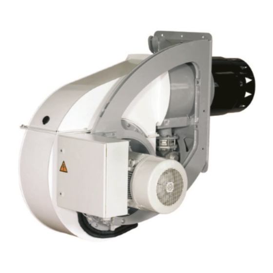
Technical data Important components, burner description N10.12000.30 N10.12000.37 N10.14000.37 N10.14000.45 N10.16000.45 Burner type G-EU2 G-EU2 G-EU2 G-EU2 FQ G-EU2 FQ important components: QRA 2, QRA 53 / FFS 06 Flame monitor Ignition transformer SAD15 / STM 30/40 Servo motor DL 50 A Air pressure switch Operating mode Other electronic burner controller... -
Page 7: Operation Fields
Technical data Operation fields Operation fields N10.12000 G-EU2 according EN 676 Arbeitsfelder N10.12000 G-EU2 nach EN 676 N10.12000.30 N10.12000.30 N10.12000.37 G-EU2 G-EU2 FQe G-EU2 N10.12000.37 G-EU2 FQe Limit full load range Combustion power output [MW] FQe=frequency converter for motor externally Operation fields N10.14000 G-EU2 according EN 676 Arbeitsfelder N10.14000 G-EU2 nach EN 676 N10.14000.37... -
Page 8: Operation Fields
Technical data Operation fields Operation fields N10.16000 G-EU2 FQe according EN 676 Arbeitsfeld N10.16000.45 G-E FQ Combustion power output [MW] FQe=frequency converter for motor externally 12/2011 14 072 205... -
Page 9: Gas Pressure Loss Burner Head Gas Pressure Loss Gas Butterfly
Technical data Gas pressure loss burner head Gas pressure loss gas butterfly Pressure loss gas mixed unit N10 ... G-EU2 Druckverluste Gas Mischeinrichtung E10 G-EU2 900 1000 1100 1200 1300 1400 1500 1600 1700 1800 1900 Operation volume flow natural gas [m /h], t=15°C, 1013 mbar, dv=0,61 Volumenstrom Erdgas [m³/h], 15°C, 1013 mbar, dv 0,61 1013... -
Page 10: Dimensional Drawing
Technical data Dimensional drawing N 10... G-EU2 The cover of motor is removable in case of ope- Drilling Template ning boiler door for revi- sion Motor with disassem- bled protection grid Air intake box cover with dismantled home 12/2011 14 072 205... -
Page 11: Installation Conditions
Technical data Installation conditions Boiler lining ad 1) = 497 = 525 = combustion chamber diameter = 150-250 (option: extensions of 100 and 200 mm) The burner lining must be installed at right angles to the burner tube. Possible trimming work (bevelling, roun- ding) as is required for reversing boi- lers, for example, should done at a diameter not below 70 % of the combu-... -
Page 12: Mounting To Boiler Electrical Connection Presetting
Installation Mounting to boiler Electrical connection Presetting Check before burner installation Attention: Burner plate with gasket strip After the completion of the electric con- Check the mixing unit for correct set- nection work make a check of the wiring ting; see dimensioned drawing. of the burner electric system. -
Page 13: Burner Head Settings
Installation Burner head settings N 10..G-EU2 Burner N10.12000 G-EU2 491/497 N10.14000 G-EU2 491/497 N10.16000 G-EU2 491/497 Adjustment electrical Ignition Operation Gas ignition burner ZB 2 Blower pressure p [mbar] 12/2011 14 072 205... -
Page 14: Gas Connection
Installation Gas connection Gas connection Gas connection pressure Leak test The gas lines and valves and instru- A minimum connection pressure must The gas line upstream of the burner gas ments group should be installed and be available upstream of the burner gas valves and instruments group must be taken into operation in accordance with valve to ensure the proper functioning... -
Page 15: Gas Train Description
Installation Gas train description The burner's scope of delivery may Gas trains with a double valve are Low- and high-pressure gas include a gas train. In this case, the bur- intended for the supply, main shut-off, trains ner and the gas train are issued with a gas filtration, gas pressure regulation If the outlet side of the regulator, i.e. - Page 16 Installation Gas train description Gas train to EN 676, high pressure Burner Min. gas pressure switch Impulse pipe gas pressure Gas pressure switch for valve leak check or valve Air flap leak checker Ball valve Actuator Gas filter Gas pressure regulator Options in accordance with country-specific requirements: Safety shut-off valve (SSV) Pressure gauge with pushbutton valve...
-
Page 17: Checking Procedure
Start-up Checking procedure Check the following prior to the Gas start-up initial operation of the boiler system: • Connect the measuring instruments • Take care to observe the operating for the gas head pressure on the test instructions supplied by the boiler connection downstream of the gas manufacturer. -
Page 18: Disassembling Firing Head
Start-up Disassembling firing head • Isolate the system from power Removing and closing the casing (Figure 2) source. Set the main switch to cover „OFF“. The casing cover is removed as follows: • Close all shut-off valves upstream of the burner. To disassemble the combustion head, - Screw out the screws (8) to (13). -
Page 19: Gas Start-Up Mode Gas Operating Mode General Safety Function
Start-up Gas start-up mode Gas operating mode General safety function The ignition transformer is commis- Depending on the heat demand the out- Gas starting function sioned. Following the pre-ignition put controller will actuate the electronic If there is a demand for heat by the fur- period, the ignition gas solenoid valves compound controller which in turn will nace system the burner control circuit... -
Page 20: Fuel-Air Compound Control
Start-up Fuel-air compound control The gas pressure should be corrected and controlled to the programmed refer- Fuel-air compound control at the gas pressure regulator if neces- ence value for the current output level. This compound pneumatic control sary. system with precision-adjustment capa- bility has been designed to allow the Equipment option: fuel and air flow rates to be steadily... -
Page 21: Electronic Burner Controller
Start-up Electronic burner controller Description The electronic burner controller is a programmable automatic combustion control unit with an integrated electronic coupled controller. There may be addi- tional functions, depending on the equipment and model. The following burner-specific controllers are used: Burner controller BCS 300 Etamatic OEM... -
Page 22: Servo Motor Type Sad 15
Start-up Servo motor type SAD 15 Electrical actuator STM 40 The electronic compound control system type BCS makes use of digitally N L PE activated servomotors type SAD 15 These consist of a stepping motor with electronic trigger and power pack. A driver with digital feedback via enco- der disk is provided for monitoring the function and direction of rotation. -
Page 23: Flame Sensor
Start-up Flame sensor The flame sensor is a component of the ner operation. is achieved by means of ionisation. In flame monitoring system. Depending on the requirements of the this case, no optical flame sensor is burner and fuels, the flame sensor may present. -
Page 24: Gas Pressure Switch Air Pressure Switch
Start-up Gas pressure switch Air pressure switch Gas pressure switch GW...A5/A6 Technical data: Gas pressure switch A5 Verbundregler für EK The pressure switch can be used to monitor either falling pressure (min.) or Type of gas: increasing pressure (max.). Gases according to DVGW Worksheet Types GW...A5/A6 are EC-type-tested G 260/1, gas families 1, 2, 3 and certified in accordance with the EC... -
Page 25: Adjustment Combination Controls Cg 15 -30
Start-up Adjustment Combination controls CG 15 -30 Combination controls CG 15-30 Complete with strainer, two safety valves (Class A) and servo- govemor für maximum control accuracy Application The combination controls are type- tested and certitied pursuant to the Gas Appliance Directive (90/396/EEC) in conjunction with EN 126 and EN 12067-1. - Page 26 Start-up Adjustment Combination controls CG 15 -30 Adjustment Governor CG..D1 Testing contol capacity After fitting, the governor must bechek- The gas outlet pressure p can beset Set burner to high fire. ked for proper functioning in con- Measure gas pressure at A and B. from junction with the gas consuming Slowly close manual valve up-stream of...
-
Page 27: Exhaust Gas Test
Start-up Exhaust gas test exhaust gases must be below the cur- Exhaust gas test To ensure an economically efficient and rently applicable specifications in all load 1000 trouble-free operation of the system it stages. ------ - ----------- - 1136kW will be necessary to adjust the burner In the fuel oil combustion mode the per- 0 88... - Page 28 Start-up Exhaust gas test Flue gas loss Flue gas loss caused by free heat Fuel oil Fuel oil Natural City gas Liquid arises as a consequence of the temper- ature difference between the fuel-air 0,50 0,490 0,370 0,350 0,420 mixture entering the combustion cham- ber and the gases that leave it.
-
Page 29: Burner Maintenance
Servicing instructions Burner maintenance Check the fan impeller for possi- gases To ensure a high operational readi- ble deformation and cracks. • CO test, soot test ness, functionality, safety and eco- Clean the UV flame sensor. • UV sensor current measurement nomic efficiency, the user should Clean the filters and screens. -
Page 30: Fan Impeller
Servicing instructions Fan impeller - Clean and degrease all bright-finished Note: surfaces. A requirement for achieving Prior to removing the fan impeller, the a high slipping moment is always a shaft or the fan impeller must be mar- clean and fat free surface of all parts ked on the edge of the suction funnel so to be fitted into one another. -
Page 31: Cause And Removal Of Disturbance
Trouble shooting instructions Cause and removal of disturbance 3. Proper functional order and setting of Proceed with searching for the cause of Important note: defective safety all control and safety instruments such the trouble and eliminate it. Unlock the boxes must always be replaced. It is as temperature controller, safety automatic furnace controller by pres- prohibited to open them and attempt... - Page 32 Trouble shooting instructions Cause and removal of disturbance 8. Cleaning and lubricating 4. Unsteady atomization 6. Mixing unit gives poor instructions Depending on the amount of dirt intro- combustion data duced by the combustion air it will be Cause Remedy Cause Remedy necessary to clean the fan impeller,...
- Page 33 Manufacturer’s declaration...
- Page 34 ELCO GmbH D - 64546 Mörfelden-Walldorf Customer Service: ELCO Austria GmbH A - 2544 Leobersdorf ELCOTHERM AG CH - 7324 Vilters ELCO Rendamax B.V. NL - 1410 AB Naarden ELCO Belgium n.v./s.a. B - 1731 Zellik ELCO Italia S.p.A I - 31023 Resana (TV)
Need help?
Do you have a question about the Low-NOx N10.12000.30 G-EU2 and is the answer not in the manual?
Questions and answers