Table of Contents
Advertisement
EKEVO 6/N6 G-E, EF3, EU2, EU2N
EKEVO 7/N7 G-E, EF3, EU2, EU3, EU2N
EKEVO 8/N8 G-E, EU3
EKEVO 9/N9 G-E, EU2, EU3, EU2N
Original Operating Instructions
For authorised specialist engineers
Gas burner
de ................................................... 4200 1087 1603
fr ..................................................... 4200 1087 2000
it ..................................................... 4200 1043 1703
nl .................................................... 4200 1087 2100
EKEVO 6/EKEVO 7 G-E
4200 1054 2001
EKEVO 6/EKEVO 7 G-EF3 4200 1054 2200
EKEVO 6/EKEVO 7 G-EU2 4200 1084 1400
EKEVO 6/EKEVO 7 G-EU2
4200 1084 1501
FGR
EKEVO 6/EKEVO 7 G-EU2N 4200 1075 2500
EKEVO 7.5800 G-EF3
4200 1085 7400
EKEVO 7.5800/EKEVO
4200 1079 0600
9.13000 G-EU2
EKEVO 7.5800/EKEVO
4200 1084 1301
9.13000 G-EU2 FGR
EKEVO 7.7000/EKEVO
4200 1104 8900
9.13000 G-EU3 FGR
EKEVO 8/EKEVO 9 G-E
4200 1060 5700
EKEVO 6/EKEVO 7 G-E
4200 1081 0102
EKEVO 6/EKEVO 7 G-EF3 4200 1066 6400
EKEVO 6/EKEVO 7 G-EU2 4200 1084 2100
EKEVO 6/EKEVO 7 G-EU2N 4200 1075 3000
EKEVO 6/EKEVO 7 G-EU2 FGR 4200 1084 2200
EKEVO 7.5800 G-EF3
4200 1085 7600
EKEVO 7.5800 G-EU2
4200 1079 0000
EKEVO 7.5800 G-EU2 FGR 4200 1084 1900
EKEVO 7.7000 G-EU3
4200 1104 9100
EKEVO 7.7000 G-EU3 FGR 4200 1104 9500
EKEVO 8/EKEVO 9 G-E
4200 1060 5800
EKEVO 8/EKEVO 9 G-EU3 4200 1060 6000
EKEVO 6/EKEVO 7 G-E
4201 1010 6700
EKEVO 6/EKEVO 7 G-EF3 4201 1010 6800
EKEVO 6/7 G-EU2
4201 1016 5500
EKEVO 6/7 G-EU2N
4201 1018 3000
EKEVO 7.5800 G-EU2
4201 1021 2600
EKEVO 7.7000 G-EU3
4201 1028 7900
EKEVO 7.7000 G-EU3 FGR 4201 1028 8000
EKEVO 8/9 G-E/G-EU3
4201 1016 1100
EKEVO 9.13000 G-EU2
4201 1021 0900
10/2019 - Art. Nr. 4200 1043 1803G
EKEVO 8/EKEVO 9 G-EU3 4200 1064 0400
EKEVO 8/EKEVO 9 G-EU3
4200 1084 1801
FGR
EKEVO 9 G-EU2N
4200 1075 2700
N6/N7 G-E
4200 1029 3003
N6/N7 G-EF3
4200 1031 7903
N6/N7 G-EU2N
4200 1075 2400
N8/N9 G-E
4200 1043 1101
N8/N9 G-EU3
4200 1043 1501
N9 G-EU2N
4200 1075 2600
EKEVO 8/EKEVO 9 G-EU3 FGR 4200 1084 2300
EKEVO 9.13000 G-EU2
4200 1079 0100
EKEVO 9.13000 G-EU2 FGR 4200 1084 2000
EKEVO 9.13000 G-EU3
4200 1104 9200
EKEVO 9.13000 G-EU3 FGR 4200 1104 9600
EKEVO 9 G-EU2N
4200 1075 3200
N6/N7 G-E
4200 1077 7500
N6/N7 G-EF3
4200 1077 7600
N6/N7 G-EU2N
4200 1075 2900
N8/N9 G-E
4200 1079 2700
N8/N9 G-EU3
4200 1079 2800
N9 G-EU2N
4200 1075 3100
EKEVO 9.13000 G-EU3
4201 1028 8100
EKEVO 9.13000 G-EU3 FGR 4201 1028 8200
EKEVO 9 G-EU2N
4201 1018 3100
N6/N7 G-E
14071611
N6/N7 G-EF3
14071633
N6/N7 G-EU2N
4201 1018 2500
N8/N9 G-EU2N/BT3
4201 1018 2700
N8/N9 G-E/G-EU
14062272
en
Advertisement
Table of Contents

Related Manuals for elco EKEVO 6 G-E


Summary of Contents for elco EKEVO 6 G-E
- Page 1 EKEVO 6/N6 G-E, EF3, EU2, EU2N EKEVO 7/N7 G-E, EF3, EU2, EU3, EU2N EKEVO 8/N8 G-E, EU3 EKEVO 9/N9 G-E, EU2, EU3, EU2N Original Operating Instructions For authorised specialist engineers Gas burner de ........... 4200 1087 1603 fr ............. 4200 1087 2000 it .............
-
Page 2: Table Of Contents
General information Contents General information Contents ............................2 Important information ........................3 Burner description ........................4-5 Installation Air duct connection, rotating air box ....................6 General information regarding burner installation ................7 Boiler lining for G-E/G-EU2/G-EU2N/G-EU3/G-EF3 burners............8 Burner installation..........................9 Combustion components Combustion components N6/N7 G-E adjustment data/check ..........10 Combustion components EKEVO 6/EKEVO 7 G-E adjustment data/check......10 Combustion components N6/N7 G-EF3 adjustment data/check ..........11 Combustion components EKEVO 6/EKEVO 7 G-EF3 adjustment data/check .......11... -
Page 3: Important Information
Any other type of application DIN EN 50156-1 Transport \ packaging \ storage requires the approval of ELCO. The Electrical equipment for firing systems burner may only be used in accordance Safety measures with the instructions set out in this... -
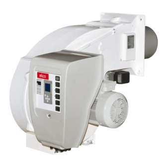
Page 4: Burner Description
General information N6/N7/N8/N9 Burner description Power controller (option) Casing Burner tube Integrated switch cabinet Burner flange Air box Lifting rings (underneath the metal cover for the N8 burner) Air pressure switch Electric motor Y10 Servomotor for air and/or gas flaps Note: The construction principle for N6 - N9 GE, GEU2, GEU2N, GEU3 and GEF3... - Page 5 The construction principle for EKEVO 6 - EKEVO 9 GE, GEU2, GEU2N, GEU3 and GEF3 burners is largely identical. To provide an example, only the scenario with burner EKEVO 6 G-E is shown on this page. 05/2019 - Art. Nr. 4200 1043 1803F...
-
Page 6: Installation Air Duct Connection, Rotating Air Box
Installation EKEVO 6/EKEVO 7/EKEVO 8/EKEVO 9 Air duct connection Rotating air box EKEVO 6/EKEVO 7 EKEVO 6/EKEVO 7 for dimensions: see technical data EKEVO 8/EKEVO 9 EKEVO 8/EKEVO 9 for dimensions: see technical data * Rotation procedure of air box: see chapter «Servicing»... -
Page 7: General Information Regarding Burner Installation
Installation General information regarding burner installation Tightening torques During installation, commissioning and maintenance, the following torques for screw connections must be observed. Max. tightening torques for accessories system, double gas valve G1/8 G1/4 G1/2 G3/4 Siemens 3 Nm 8 Nm 15 Nm 35 Nm 7 Nm... -
Page 8: Boiler Lining For G-E/G-Eu2/G-Eu2N/G-Eu3/G-Ef3 Burners
Installation Boiler lining for G-E, G-EU2, G-EU2N, G-EU3, G-EF3 burner Boiler lining The burner lining must be installed at a right angle to the burner tube. Possible trimming work (bevelling, rounding) as required for reverse boilers, for example, should done at a diameter not below 70% of the combustion chamber diameter. -
Page 9: Burner Installation
Installation Burner installation Burner flange seal (option 1) thermocord, the operator should wear The surface of the The sealing tape in the accessories kit loose-fitting, long-sleeved clothing. In Seal corners with entire circumference sealing tape must be affixed to the burner as shown the event of high fibre dust must be sealed in the drawing below. -
Page 10: Combustion Components
Installation Combustion components Combustion components N6/N7 G-E adjustment data/check Combustion components EKEVO 6/EKEVO 7 G-E adjustment data/check N6/N7 G-E EKEVO 6/EKEVO 7 G-E Natural gas mode Propane gas mode ø ø Burner (mm) (mm) (mm) (mm) N6.2400 / EKEVO 6.2400 N6.2900 / EKEVO 6.2900 N7.3600 / EKEVO 7.3600 N7.4500 / EKEVO 7.4500... -
Page 11: Combustion Components N6/N7 G-Ef3 Adjustment Data/Check
Installation Combustion components Combustion components N6/N7 G-EF3 adjustment data/check Combustion components EKEVO 6/EKEVO 7 G-EF3 adjustment data/check N6/N7 G-EF3 EKEVO 6/EKEVO 7 G-EF3 Burner N6.2400 / EKEVO 6.2400 N6.2900 / EKEVO 6.2900 N7.3600 / EKEVO 7.3600 N7.4500 / EKEVO 7.4500 EKEVO 7.5800 Natural gas mode Propane gas mode... -
Page 12: Combustion Components Ekevo 6/7 G-Eu2 Adjustment Data/Check
Installation Combustion components Combustion components EKEVO 6/7 G-EU2 adjustment data/check Three-pass boiler EKEVO 6 G-EU2 / 400 520 640 263 THREE-PASS BOILER EKEVO 7 G-EU2 / 420 550 680 325 THREE-PASS BOILER 05/2019 - Art. Nr. 4200 1043 1803F... - Page 13 Installation Combustion components Combustion components EKEVO 6/7 G-EU2 adjustment data/check Boiler with reverse firing EKEVO 6 G-EU2 / BOILER WITH REVERSE 400 520 640 263 FIRING EKEVO 7 G-EU2 / BOILER WITH REVERSE 420 550 680 325 FIRING 05/2019 - Art. Nr. 4200 1043 1803F...
-
Page 14: Combustion Components Ekevo 6 G-Eu2 Fgr Adjustment Data/Check
Installation Combustion components Combustion components EKEVO 6 G-EU2 FGR adjustment data/check EKEVO 6 G-EU2 FGR 400 520 640 05/2019 - Art. Nr. 4200 1043 1803F... -
Page 15: Combustion Components Ekevo 6 G-Eu2 Fgr Adjustment Data/Check
Installation Combustion components Combustion components EKEVO 7 G-EU2 FGR adjustment data/check baffle plate from the baffle plate to the nozzle from the baffle plate to the nozzle EKEVO 7 G-EU2 FGR 420 550 680 05/2019 - Art. Nr. 4200 1043 1803F... -
Page 16: Combustion Components N6/7/9 G-Eu2N Adjustment Data/Check
Installation Combustion components Combustion components N6/7/9 G-EU2N adjustment data/check Combustion components EKEVO 6/7/9 G-EU2N adjustment data/check Burner N6.2200 G-EU2N EKEVO 6.2200 G-EU2N N7.3400 G-EU2N EKEVO 7.3400 G-EU2N N9.7200 G-EU2N EKEVO 9.7200 G-EU2N N9.7500 G-EU2N EKEVO 9.7500 G-EU2N 05/2019 - Art. Nr. 4200 1043 1803F... -
Page 17: Combustion Components Ekevo 7.5800 G-Eu2 Adjustment Data/Check
Installation Combustion components Combustion components EKEVO 7.5800 G-EU2 adjustment data/check Boiler with reverse firing EKEVO 7 G-EU2 / BOILER WITH REVERSE 420 550 680 325 1... 2 FIRING 05/2019 - Art. Nr. 4200 1043 1803F... -
Page 18: Combustion Components Ekevo 7.5800 G-Eu2/Fgr Adjustment Data/Check
Installation Combustion components Combustion components EKEVO 7.5800 G-EU2/FGR adjustment data/check Three-pass boiler EKEVO 7 G-EU2/FGR / 420 550 680 325 1... 2 THREE-PASS BOILER 05/2019 - Art. Nr. 4200 1043 1803F... -
Page 19: Combustion Components Ekevo 7.7000 G-Eu3 / G-Eu3 Fgr Adjustment Data/Check
Installation Combustion components Combustion components EKEVO 7.7000 G-EU3 / G-EU3 FGR adjustment data/ check Réglage de l’électrode d’allumage Adjustment of the ignition electrode * Fermeture seulement avec FGR * Closing only with FGR (+B-B) (+B-B) Diffuseur de maintien IIb (1x) Retaining nozzle IIb (1x) Diffuseur de maintien IIa (1x) + électrode Retaining nozzle IIa (1x) + ignition... -
Page 20: Combustion Components N8/N9 G-E Adjustment Data/Check
Installation Combustion components Combustion components N8/N9 G-E adjustment data/check Combustion components EKEVO 8/EKEVO 9 G-E adjustment data/check N8 / EKEVO 8 (1) Dimension up to the previous edge of the turbulator Gas nozzle is touching the baffle plate N9 / EKEVO 9 (1) Dimension up to the previous edge of the turbulator Gas nozzle is touching the baffle plate N8.5800 / EKEVO 8.5800... -
Page 21: Combustion Components N8/N9 G-Eu3 Adjustment Data/Check
Installation Combustion components Combustion components N8/N9 G-EU3 adjustment data/check Combustion components EKEVO 8/EKEVO 9 G-EU3 adjustment data/check N8 / EKEVO 8 (1) Dimension up to the previous edge of the turbulator N9 / EKEVO 9 (1) Dimension up to the previous edge of the turbulator N8.5800 / EKEVO 8.5800 N8.7100 / EKEVO 8.7100 N9.8700 / EKEVO 9.8700... -
Page 22: Combustion Components Ekevo 8 G-Eu3 Fgr Adjustment Data/Check
Installation Combustion components Combustion components EKEVO 8 G-EU3 FGR adjustment data/check Insert the diffuser nozzles into the swirl generator EKEVO 8 G-EU3 FGR 500 640 780 05/2019 - Art. Nr. 4200 1043 1803F... -
Page 23: Combustion Components Ekevo 9 G-Eu3 Fgr Adjustment Data/Check
Installation Combustion components Combustion components EKEVO 9 G-EU3 FGR adjustment data/check Adjust the baffle plate Adjust the diffuser nozzles Insert the diffuser nozzles into the swirl generator Adjust the pad nozzles Adjust the plate nozzles to the end of The plate nozzles are the electrode positioned at a tangent to the baffle plate... -
Page 24: Combustion Components Ekevo 9.13000 G-Eu2 Adjustment Data/Check
Installation Combustion components Combustion components EKEVO 9.13000 G-EU2 adjustment data/check Boiler with reverse firing KN KM EKEVO 9.13000 G-EU2/ BOILER WITH 550 700 850 431,5 REVERSE FIRING 05/2019 - Art. Nr. 4200 1043 1803F... -
Page 25: Combustion Components Ekevo 9.13000 G-Eu2/Fgr Adjustment Data/Check
Installation Combustion components Combustion components EKEVO 9.13000 G-EU2/FGR adjustment data/ check Three-pass boiler KN KM EKEVO 9.13000 G-EU2/ FGR / 550 700 850 431,5 THREE-PASS BOILER 05/2019 - Art. Nr. 4200 1043 1803F... -
Page 26: Combustion Components Ekevo 9.13000 G-Eu3 / G-Eu3 Fgr Adjustment Data/Check
Installation Combustion components Combustion components EKEVO 9.13000 G-EU3 / G-EU3 FGR adjustment data/check Insert the diffuser nozzles into the swirl generator Gas nozzle is touching the baffle plate 05/2019 - Art. Nr. 4200 1043 1803F... -
Page 27: Ignition Electrodes N6/N7 G-E/G-Ef3 Adjustment Data/Check
Installation Combustion components Ignition electrodes N6/N7 G-E/G-EF3 adjustment data/check Ignition electrodes EKEVO 6/EKEVO 7 G-E/G-EF3 adjustment data/check Note: If there are any ignition or flame detection problems, check the setting and dimensions of the electrodes. If the wear is too great, replace the electrodes. -
Page 28: Ignition Electrodes N6/7/9 G-Eu2/G-Eu2N Adjustment Data/Check
Installation Combustion component Ignition electrodes N6/7/9 G-EU2/G-EU2N adjustment data/check Ignition electrodes EKEVO 6/7/9 G-EU2/G-EU2N/G-EU3 adjustment data/ check Note: If there are any ignition or flame detection problems, check the setting and dimensions of the electrodes. If the wear is too great, replace the electrodes. -
Page 29: Ignition Electrodes N8/9 Ekevo 8/9 G-E/G-Eu3 Adjustment Data/Check
Installation Combustion component Ignition electrodes N8/9 EKEVO 8/9 G-E/G-EU3 adjustment data/check Ionisation electrode N8/9 EKEVO 8/9 G-E/G-EU3 adjustment data/check Ignition electrodes Note: If there are any ignition or flame detection problems, check the setting and dimensions of the electrodes. If the wear is too great, replace the electrodes. -
Page 30: Montage
It is not necessary to modify the combustion components. Note: To provide an example, only the scenario with burner N9 G-EU3 is shown. Note: To provide an example, only the scenario with burner EKEVO 6 G-E is shown. 05/2019 - Art. Nr. 4200 1043 1803F... -
Page 31: Gas Train
Installation Gas train Description of gas train with VGD... Description Gas train installation Gas train with VGD To fit the gas train supplied to the Gas trains with a Siemens VGD double Technical data: burner, the screw connections and seals valve are intended for the supply, main Types of gas: provided for this must be used (supplied... -
Page 32: Description Of Gas Train With Mbc
Installation Gas train Description of gas train with MBC... Description Gas train selection Gas train with MBC The gas fitting trains with Dungs MBC ... The gas train is defined on a system- Technical data: double gas valves MBC... are used for specific basis. -
Page 33: Basic Design
Installation Gas train Basic design Gas train to EN 676, low pressure 100 Burner 349 Servomotor 101 Impulse pipe gas pressure 120 Air flap Options in accordance with country-specific requirements: 141 Ball valve 143 Pressure gauge with pushbutton valve 142 Gas filter 147 Test burner with pushbutton valve 150 Gas control damper 148 Compensator... -
Page 34: Gas Train Components
Gas train components Description of double gas valve VGD with SKP servo motors Technical specifications VGD double gas valves with SKP actuators: Type of gas: Gasses in accordance with DVGW worksheet G 260/1, gas families 1, 2, 3 and biogas (H S content 0.1 vol.% max.), H Electrical data:... -
Page 35: Description Of Double Gas Valve Mbc
Gas train components Description of double gas valve MBC... (gas multiblock) Pressure taps Technical data MBC-300/ 700... Gas multiblock MBC-.../SE: Type of gas: Gases in accordance with DVGW worksheet G 260/1, gas families 1, 2, 3 Electrical data: 230 V -15% + 10%, other MBC-1200... -
Page 36: Overview Of Electrical Connection
Gas train components Overview of electrical connection Description of double gas valve MBC... (gas multiblock) Earthing in accordance with local Electrical connection MBC-300-1200 SE regulations. Electrical connection MBC-1900-7000 SE 05/2019 - Art. Nr. 4200 1043 1803F... -
Page 37: Replacing The Mbc-300-700-1200 Filter
Gas train components Replacing the MBC-300-700-1200 filter Adjusting the MBC-300-700-1200-SE pressure regulation component Filter inspection must be carried out at least once a year Replace filter if p between pressure port 1 and 2 > 10 mbar. Replace filter if p between pressure port 1 and 2 is twice as high as the measurement from the last inspection. -
Page 38: Setting The Mbc-1900-5000-Se Pressure Regulation Component
Gas train components Adjusting the MBC-1900-5000-SE pressure regulation component Adjusting the MBC-1900-5000-SE 5. Apply a security seal to the adjusting pressure regulation component screw (see below). 1. Open the protective caps. Optimum combustion and ignition safety must be ensured. 2. Start the burner, correction of set values possible while burner in operation (see figure). -
Page 39: Gas Filter Test Burner
Gas train components Gas filter Test burner Installation and mounting of the gas filter The filter must be installed in a horizontal pipe. The vertical position of the cover makes cleaning easier. Be aware of the gas flow direction (see arrow on the filter housing). -
Page 40: Gas Pressure Switch
Gas train components Gas pressure switch Gas pressure switch GW...A5/A6 Gas pressure switch A5 Technical data: The gas pressure switch is designed to monitor the gas flow pressure. It can be Type of gas: used for monitoring either falling Gases according to DVGW Worksheet pressure (minimum) or rising pressure G 260/1, gas families 1, 2, 3 (maximum, specified for equipment... -
Page 41: Installation Air Pressure Switch
Installation Air pressure switch Air pressure switch in other important gas consumption The air pressure switch is provided for countries. monitoring the pressure of the N.B.(Gas and air pressure switches) combustion air fan. Pressure switch The pressure switches must be set in LGW... -
Page 42: Commissioning Electronic Burner Controller
Commissioning Electronic burner controller Description The electronic burner controller is a programmable automatic firing device with an integrated electronic compound controller. There may be additional functions, depending on the equipment and model. The following burner-specific controllers are used. Burner controller BT 320 BT 330 Manufacturer... -
Page 43: Switch Cabinet Door Layout
Commissioning Switch cabinet door layout Manual terminal for controlling the N6/N7/N8/N9 burner control unit Switch / light indicator control voltage Power control +/- Manual / Automatic switch Local - 0 REMOTE switch Power controller (option) Manual terminal for controlling the EKEVO 6/EKEVO 7/EKEVO 8/EKEVO 9 burner control unit Switch / light indicator control... -
Page 44: Servomotor Ste
Commissioning Servomotor STE Servomotor STM40 The BT300 electronic control system works with the STE4.5 numerically controlled servomotor. For monitoring the function and direction of rotation, there is a driver with digital feedback via encoder disc. Observe the commissioning procedure for BT300. The connection is documented in the burner wiring diagram. -
Page 45: Lamtec 6 / 16 Nm Servomotor
Commissioning Lamtec 6 / 16 Nm servomotor Technical data 6 Nm: Voltage: 230 V AC Frequency: 50 Hz Angle of rotation: 90° Running time: 60 sec. for 90° Nominal torque: 6 Nm Static holding moment: 4,5 Nm Dimensions (W x H x D): 101 mm x 117 mm x 170,5 mm Potentiometer (fitted): 5 k... -
Page 46: Flame Sensor
Commissioning Flame sensor The flame sensor is a component of the Depending on the requirements of the In some gas burners, flame monitoring flame monitoring system. burner and fuels, the flame sensor may is achieved by means of ionisation. In be an optical sensor that monitors light this case, no optical flame sensor is In interaction with the automatic... - Page 47 A [mm] α [°] α [°] α [°] N6/EKEVO 6 G-EF3 / G-EU2 N7/EKEVO 7 G-EF3 / G-EU2 N6/EKEVO 6 G-E N7/EKEVO 7 G-E N6/EKEVO 6.2200 G-EU2N N7/EKEVO 7.3400 G-EU2N EKEVO 7 G-EU2 / G-EU3 N8/N9 G-E/G-EU3 EKEVO 8/EKEVO 9 G-E/G-EU3...
-
Page 48: Gas Fitting Connection Electrical Connection Checks Before Commissioning
Commissioning Gas fitting connection Electrical connection Checks before commissioning All electrical installation and WARNING: connection work must only be carried Electrical shock hazard! There is a risk out by a suitably qualified electrician. of coming into contact with live parts! N.B.: The applicable This could lead to fatal electrical shock! guidelines and directives... -
Page 49: Gas Connection
Commissioning Gas connection Gas connection Gas properties Leak test The gas lines and trains should be Prior to any installation work make sure The fitted gas train must be leak tested installed and taken into operation in to obtain the following data from the gas on the system in accordance with accordance with the applicable supply company:... -
Page 50: Fuel-Air Compound Controller
Commissioning Fuel-air compound control Fuel-air compound control Please note: Equipment option: This finely tuned compound control The gas outlet pressure (gas regulating control / CO control system, which uniformly adjusts the fuel pressure) must always be less than the To improve the efficiency of the system, and air volume, makes it possible for the the combustion manager can be gas inlet pressure but higher than the... -
Page 51: Burner Power Adjusting Sequence
Commissioning Burner power adjusting sequence The burner is operated and adjusted Adjusting sequence behaviour, etc.). using a handheld device or a PC (serial (Short description) Note: interface). • Switch on burner (switch on control A gas pressure setting must be selected voltage and control chain), that keeps the gas flap as wide open as For information on startup and... -
Page 52: Inspection
Commissioning Inspection Before commissioning the system for Gas commissioning Note for positioning the gas throttle the first time, the following in N8/N9/EKEVO 8/EKEVO 9 burners inspections must be carried out: • Connect the test devices for the gas head pressure on the test connection The position indicator on the gas throttle •... -
Page 53: Preventilation
Commissioning Preventilation Preventilation: Assuming the conditions in the area or Please note: Care must be taken to ensure that the the boiler unit in the case of electronic boiler system is adequately are the same for preventilation and compound controls (BT300/ standard burner operation (loss of boiler Etamatic), the nominal load and nominal preventilated. -
Page 54: Gas Start-Up Mode
Commissioning Gas start-up mode Gas operating mode General safety functions Gas start-up mode After the pre-ignition time, the main gas Depending on the heat demand, the As soon as the furnace is required to valves are open and the gas comes out output controller will actuate the supply heat, the burner control circuit will from injectors where it is mixed in the... -
Page 55: Servicing Maintenance
Servicing Maintenance Burner and boiler servicing must only - Check the ignition electrodes and Cleaning and lubricating instructions be carried out by a professionally ignition sparking. Clean and readjust if - Depending on the cleanliness status of qualified heating engineer. The necessary the combustion air, the fan impeller, system operator is advised to take... -
Page 56: Maintenance Replacing The Control Unit
Servicing Maintenance Replacing the control unit Warning! parts. Using defective or damaged com- tion, and may even cause injury (risks of Replace any damaged or defective com- ponents may cause malfunctioning and serious or fatal injury). ponents! Replace safety components hazardous operation. - Page 57 Servicing Maintenance Checking the combustion N8/N9 N6/N7 components • N6/N7 : Unscrew the 2 screws S, remove the burner cover. • N8/N9 : Live the front end of the burner and remove rearwardly. • EKEVO : Unscrew the 6 screws W, remove the housing cover.
-
Page 58: Maintenance, Checking / Installing The Combustion Components
Servicing Maintenance Checking / installing the combustion components Filter replacement Checking the flue gas temperature • Check the flue gas temperature at • The multiblock filter screen (only Important regular intervals. applies to MBC...) must be checked at After every operation: check the •... -
Page 59: Rotation Procedure Of Air Box Ekevo 6/Ekevo 7
Servicing EKEVO 6/EKEVO 7 Rotation procedure of air box Rotation procedure of air box Remove the flexible air hose. Disassemble the servomotor from the air flap and fasten it to the casing. Disassemble the cover of the air box. Unfasten the air box support, swing it towards the new desired position and fasten it again (rotation possible in 45°... -
Page 60: Rotation Procedure Of Air Box Ekevo 8/Ekevo 9
Servicing EKEVO 8/EKEVO 9 Rotation procedure of air box Installation instructions for air box rotation on the burner By default the air box opening on the EK EVO is pointing in the direction of the boiler. However, if an air duct connection is provided, it is possible to orient the air box, with certain adjustments, in the direction of this duct. - Page 61 Servicing EKEVO 8/EKEVO 9 Rotation procedure of air box 6. Removing and rotating the air box closed. The drive can then be coupled to support the air flap shaft. Retighten the screws Before you can orient the air box in the on the coupling.
- Page 62 Servicing EKEVO 8/EKEVO 9 Rotation procedure of air box Figure Wiring adjustment Air pressure switch pressure tap Basic position Pos. A as basic position 45° Pos. A 3 additional adhesive attachment flanges on burner feet 90° Pos. A 3 additional adhesive attachment flanges on burner feet 135°...
-
Page 63: Air Fan Setting N6/N7/N8/N9 - Ekevo 6/7/8/9
1 - Blower turbine 2 - Air conveyor Burner L [mm] Burner L [mm] N7.3600/4500 G-EF3 N6/EKEVO 6 G-E EKEVO 7.3600/4500 G-EF3 EKEVO 7.4500 G-EU2 N7.3600 G-E N7.3400 G-EU2N EKEVO 7.3600 G-E EKEVO 7.3400 G-EU2N EKEVO 7.3600 G-EU2 EKEVO 7.5800 G-EF3 EKEVO 9.13000 G-EU2... -
Page 64: Air Fan Setting Ekevo 6/7
Servicing Fan wheel setting EKEVO 6/7 Because of its design the turbine can be fitted to the drive shaft only in a fixed position. The same position is consequently ensured every time it is assembled. There is no need for any further adjustment of the axial cover through the air conveyor. -
Page 65: Exhaust Gas Measurement
Servicing Exhaust gas measurements Exhaust gas measurement the permissible smoke spot number in the Gas temperature 15 °C In order to ensure efficient and fault-free exhaust gas must not be exceeded. Standard pressure 1013 mbar operation, the burner must be adjusted with Calculating the volumetric flow rate for reference to the specific system. -
Page 66: Diagnosing And Remedying Faults
Servicing Exhaust gas measurements Diagnosing and remedying faults Exhaust gas loss Natural Town Exhaust gas loss by way of free heat will Fuel-oil EL Fuel-oil S Liquid gas occur as a result of the temperature difference between the fuel-air mixture 0.50 0.490 0.370... - Page 67 Servicing Diagnosing and remedying faults 5. Combustion components - 4. No response to flame by poor combustion values Automatic firing device heavy internal oil deposits with flame sensor or heavy coke deposits (fuel-oil mode) Cause Remedy Cause Remedy Dirty flame Clean.
-
Page 68: Faults
Servicing Faults Smell of gas, danger of gas If system faults occur, proceed with The start-up program will be initiated • Shut down the burner checking the basic conditions for and should be carefully monitored. proper operation of the system. •... -
Page 69: Manufacturer Certification In Accordance With 1. Bimschv
05/2019 - Art. Nr. 4200 1043 1803F... - Page 70 05/2019 - Art. Nr. 4200 1043 1803F...
- Page 71 05/2019 - Art. Nr. 4200 1043 1803F...
- Page 72 Made in the EU. Non contractual document. 10/2019 - Art. Nr. 4200 1043 1803G...
Need help?
Do you have a question about the EKEVO 6 G-E and is the answer not in the manual?
Questions and answers