Table of Contents
Advertisement
Available languages
Available languages
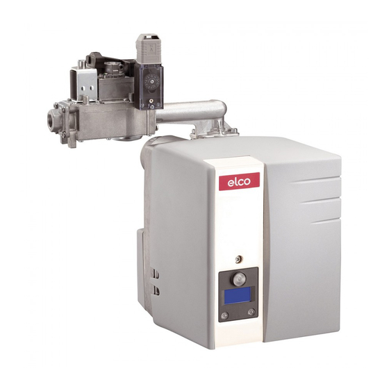
VG 1.40 (/TC)
VG 1.55 (/TC)
VG 1.85 (/TC)
VG 1.105 (/TC)
Bedieningshandleiding
Voor de gespecialiseerde vakman
Aangeblazen gasbrander
Operating instructions
For specialist installation engineers
Gas burners
de, fr, it............................ 4200 1015 8201
nl, en................................ 4200 1016 3901
de, fr, it, nl, en................. 4200 1016 3801
......................................... 4200 1071 9203
10/2016 - Art. Nr. 4200 1016 3901A
VG1 /TC 4201 1000 4100
VG1 4201 1000 1601
nl
en
Advertisement
Chapters
Table of Contents

Related Manuals for elco VG 1.40


Summary of Contents for elco VG 1.40
- Page 1 VG 1.40 (/TC) VG 1.55 (/TC) VG 1.85 (/TC) VG 1.105 (/TC) Bedieningshandleiding Voor de gespecialiseerde vakman Aangeblazen gasbrander Operating instructions For specialist installation engineers Gas burners de, fr, it......4200 1015 8201 nl, en........ 4200 1016 3901 de, fr, it, nl, en....4200 1016 3801...
-
Page 2: Table Of Contents
Storingen verhelpen ..........18 Aanduiding onderhoudsinterval........19 Voor schade, om de volgende Belangrijke aanwijzingen 1 Branderflens met isolatiering De branders VG 1.40/55/85/105 zijn 1 Zakje met bevestigingsonderdelen redenen ontstaan, sluiten wij garantie erop berekend aardgas en propaan te 1 Etui met Technische Documentatie... -
Page 3: Beschrijving Van De Brander
Overzicht Branderbeschrijving Branderautomaat Display Ionisatiebrug Luchtpressostaat Sluiterschijf voor propaangas Elektromotor Luchtdruknippel Ontstekingstransformator Gasblokaansluitflens Bevestigingsschroeven voor basisplaat Inhangvoorziening (Service) Behuizing Elektrische aansluiting (bedekt) Ontgrendelingsknop Gaskopinstelschroef Afdekkap Branderaansluitflens Branderbuis 103B Luchtregeling Luchtkast 10/2016 - Art. Nr. 4200 1016 3901A... -
Page 4: Gasblok Vr4625 / Mb-Dle407
Werking Gasblok VR4625 / MB-DLE 407 De compacte eenheid met geïnte- VR4625 greerde gasdrukregeling VR 4625 is geschikt voor de werking van enkeltraps aangeblazen gasbranders. Het compacte gasblok is geregistreerd onder nummer: CE-0063AP3090 Technische gegevens Ingangsdruk 15-60mbar Omgevingstemperatuur 0 tot +60° C Spanning 230 V/50 Hz Opgenomen vermogen... - Page 5 Werking Branderautomaat TCG 1xx met functie TC De gasbranderautomaat TCG 1xx stuurt De knop R … veroorzaakt ... en bewaakt de aangeblazen brander. indrukken tijdens Door het microprocessorgestuurde programmaverloop worden uiterst … 1 seconde ... Ontgrendelen van de stabiele tijden bereikt, die onafhankelijk automaat zijn van schommelingen in netspanning en omgevingstemperatuur.
- Page 6 Werking Branderautomaat TCG 1xx zonder functie TC De gasbranderautomaat TCG 1xx stuurt De knop R … veroorzaakt ... en bewaakt de aangeblazen brander. indrukken tijdens Door het microprocessorgestuurde programmaverloop worden uiterst … 1 seconde ... Ontgrendelen van de stabiele tijden bereikt, die onafhankelijk automaat zijn van schommelingen in netspanning en omgevingstemperatuur.
-
Page 7: Aansluitschema Aansluitsokkel
Werking Aansluitschema Aansluitsokkel Afstandsontgren Vlamcontrole Gaspressostaat Luchtpressostaat Stroomvoeding L1 Aarde deling Stekker Klem Aarde Magneetventiel Brandermotor Ontste- Display Storing Stekker Klem Klem Benaming Stekker nr. Klem Benaming Stekker nr. Signaal vlamdoofveiligheid Fase onstekingstransformator Neutraal Neutraal Fase Fase brandermotor Signaal afstandsontgrendeling Aarde Fase Neutraal... -
Page 8: Werkings- En Veiligheidsfunctie
Werking Werkingsfunctie Veiligheidsfunctie Werkingsfunctie Bewaking voorventilatie of de werking volgt (Branders met functie TC) De vlam wordt bewaakt door een uitschakelen in storingstoestand. Bij het voor de eerste maal inschakelen, ionisatiesonde. De sonde is geïsoleerd - Bij gasgebrek gaat de brander niet in na een stroomonderbreking of een op de gaskop gemonteerd en voert door werking of wordt uitgeschakeld. - Page 9 Werking Werkingsfunctie Veiligheidsfunctie (Branders zonder functie TC) Gasgebrekbeveiliging Luchtgebrekbeveiliging Hoofdmagneetventiel Veiligheidsmagneetventiel Thermisch gestuurde veiligheidsafsluiter (ter plekke aan te brengen) Gasdrukregelaar Zeef Gaskogelkraan (ter plekke aan te brengen) 119pBr Meetpunt gasuitlaatdruk 119.1 Meetpunt gasdruk in tussenruimte ventielen 119.2 Meetpunt luchtdruk Compact gasblok 10/2016 - Art.
-
Page 10: Brandermontage, Branderinbouwstand
Gebruik diafragma D ligt. Brander Gassoort Diafragma • Gasblok rechts of links bevestigen (zie hieronder voor andere VG 1.40 Aardgas zilver Ø 6,7 mm inbouwstanden). Propaangas zwart Ø 4,5 mm Montage gasdiafragma D (VG1.40) (zie tabel aan de rechterkant) VG 1.55/ Aardgas •... -
Page 11: Werking Met Propaan Elektrische Aansluiting
Montage Werking met propaan Elektrische aansluiting Instelling van de ionisatiesonde en de onstekingselektrode Zie afbeelding Tekening 1 : Standaardinstelling Tekening 2 : Instelling van de branderkop voor oudere verwarmingsketels met tendens tot CO-uitstoot • De twee schijven C tussen de stuw- schijf A en het aardgasdiafragma D monteren. -
Page 12: Testen Voor De Inwerkingstelling
Inwerkingstelling Testen voor de inwerkingstelling Ionisatiestroommeting Testen voor de inwerkingstelling Controle programmaverloop van de Voor de inwerkingstelling van de brander zonder vlamvorming brander moeten volgende testen en De branderautomaat activeert bij het controles worden uitgevoerd. eerste inschakelen de - Werkingsvoorschriften van de dichtheidscontrole. -
Page 13: Instelgegevens Luchtregeling
Inwerkingstelling Instelgegevens Luchtregeling G a s d r u k L u c h td o s e e r - L u c h t d r u k In s te llin g B r a n d e r - M a a t A a n z u ig lu c h t- G a s -... -
Page 14: Instelling Van De Compacte Gaseenheid Vr4625
Inwerkingstelling Instelling Compacte gaseenheid VR4625 Instelling compacte gaseenheid Voorbeeld: Op de meetpunten 119 en 119pBr Voor een vermogen van 25kW met een De sluiterschroeven losdraaien en G1.40 zijn volgende instellingen van drukmeetapparaten aansluiten. kracht: - Instelling branderkop: 20mm Instelling drukregelaar - Luchtklepstand: 7 De drukregelaar (schroef C) is in de - Instelling van de gasdruk op... -
Page 15: Mb-Dle407
Inwerkingstelling Instelling Compacte gaseenheid MB-DLE407 Instelling drukregelaar Instelling startlasthoeveelheid - Voor het instellen van de uitgangsdruk snelslaginstelling zijn 60 slagen van de instelschroef • Beschermkap 5 eraf draaien en over mogelijk. Drie slagen rechtsom 180° gedraaid als regelgereedschap verhogen de druk met 1 mbar, drie gebruiken. -
Page 16: Instelling Van De Luchtpressostaat
Inwerkingstelling Instelling luchtpressostaat Instelling gaspressostaat Werkingscontrole I nstelling gaspressostaat • De instelschijf rechtsom draaien, tot de gaspressostaat de brander • Voor instelling van de uitschakeldruk: uitschakelt. Het deksel van de gaspressostaat • Door verder rechtsom draaien de verwijderen. gaspressostaat 10% hoger dan de •... -
Page 17: Onderhoud
Service Onderhoud Servicewerkzaamheden aan de ketel Controle van de rookgastemperatuur en brander mogen alleen door • regelmatig de rookgastemperatuur geschoolde verwarmingsvakmensen controleren. worden uitgevoerd. Om een • Ketel reinigen, als de regelmatige uitvoering van het rookgastemperatuur de waarde van onderhoud te waarborgen, moet aan de inbedrijfstelling met meer dan 30°C de gebruiker van de installatie het overschrijdt. -
Page 18: Storingen Verhelpen
Service Storingen verhelpen Oorzaken en verhelpen van Als de storing blijft bestaan, de volgende Gebruik alleen originele storingen tabel gebruiken. onderdelen van de fabrikant. Bij storingen moeten de principiële voorwaarden voor een goede werking De componenten die met veiligheid Aanwijzing: worden gecontroleerd: verband houden, mogen niet worden... -
Page 19: Aanduiding Onderhoudsinterval
Service Aanduiding onderhoudsinterval Gedurende de werking kunnen na enige tijd de volgende inlichtingen verschijnen: Dat betekent dat het tijd is voor onderhoud door een vakman. Als de installateur zijn telefoonnummer heeft opgetekend, dan verschijnt dat, alsook het nummer van het afgesloten onderhoudscontract (toegankelijk via het... -
Page 20: Contents
Burner description telephone number of the nearest Gas lines The VG 1.40/55/85/105 are single- customer service centre. When routing gas lines and trains, stage, fully automatic, monoblock type observe the general installation Notes for the operator burners. -
Page 21: Burner Description
Overview Burner description Control and safety unit Display Ionisation bridge Air pressure switch Sealing washer for Liquefied Petroleum Gas Electric motor Air pressure nipple Ignition transformer Gas train connecting flange Fastening screws for equipment plate Securing device (service) Housing Electrical connection (covered) Release knob Gas head adjusting screw Cover... -
Page 22: Gas Train Vr4625 / Mb-Dle407
Function Gas train VR4625 / MB-DLE 407 The compact unit VR4625 with VR4625 integrated gas pressure regulation is suitable for the operation of single-stage forced-draught gas burners. The compact gas train is registered under the no.: CE-0063AP3090 Technical specifications Inlet pressure 15-60 mbar Ambient temperature 0 to +60 °C... - Page 23 Function Automatic control unit TCG 1xx with TC function The TCG 1xx automatic gas combustion Pressing and ... leads to ... control unit controls and monitors the forced- holding the R draught burner. The microprocessor- button for ... controlled programme sequence ensures maximum stability of time periods, regardless …...
-
Page 24: Automatic Combustion Control Unit
Function Automatic combustion control unit TCG 1xx without TC function The TCG 1xx automatic gas combustion Pressing and ... leads to ... control unit controls and monitors the forced- holding the R draught burner. The microprocessor- button for ... controlled programme sequence ensures maximum stability of time periods, regardless …... -
Page 25: Allocation Chart Connection Socket
Function Allocation chart Connection socket Remote Air pressure Flame monitor Gas pressostat L1 power supply Earth unlocking switch Connector Terminal Earth Solenoid valve Burner motor Firing Malfunction light Connecto r no. Terminal Terminal Designation Connector no. Terminal Designation Connector no. Flame monitor signal Ignition transformer phase Neutral... -
Page 26: Operation, Safety Functions
Function Operating function Safety function Operation function through the baffle plate into the flame pressure, a further waiting time of 2 (Burners with TC function) zone. The sensor must not have any minutes follows. The waiting time can When the system is switched on for the electrical contact with earthed parts. - Page 27 Function Operating function Safety function (Burners without TC function) Gas failure detection Air failure detection Main solenoid valve Safety solenoid valve Thermally-triggered safety shut-off valve (installation- resident) Gas pressure regulator Screen Gas ball valve (installation- resident) 119pBr Measuring point for gas outlet pressure 119.1 Measuring point for gas...
-
Page 28: Burner Assembly, Burner Installation Position
Assembly Burner assembly Burner installation position Gas connection, installation location Burner assembly combustion chamber. The burner flange 3 is equipped with Installation: elongated holes and can be used with a • Secure connecting flange 3 to the hole circle diameter of 150 - 170 mm. boiler using screws 4 These dimensions comply with EN 226. -
Page 29: Liquefied Petroleum Gas, Electrical Connection
Assembly Liquefied Petroleum Gas operation Electrical connection Setting the ionisation probe and ignition electrode See diagram Diagram 1: Standard setting Diagram 2: Burner head setting for older heating boilers with tendency toward CO emissions • Fit the two plates C between baffle plate A and natural gas shutter D. -
Page 30: Checks Before Commissioning
Start up Checks before start-up Ionisation current measurement Checks before start-up Burner program sequence test Before commissioning the burner, the without flame formation following checks and inspections are to The burner control unit activates the first be carried out time the sealing test is activated. Gas - Operating instructions of the heat pressure is required for this. -
Page 31: Adjustment Data Air Regulation
Start up Adjustment data Air regulation B u r n e r B u r n e r A i r f l a p h e a d G a s T y p e B u r n e r h e a d g a s D i m e n s i o n A i r i n t a k e... -
Page 32: Setting The Vr4625 Compact Gas Unit
Start up Setting the VR4625 compact gas unit Setting the compact gas unit Example: Loosen screw plugs at measuring points To set a power of 25 kW with a G1.40, 119 and 119 pBr and connect apply the following settings: measuring devices. -
Page 33: Setting The Mb-Dle407 Compact Gas Unit
Start up Setting the MB-DLE407 compact gas unit Pressure controller setting Initial load flow adjustment - rapid The adjusting screw has a path of 60 stroke adjustment turns for adjusting the output pressure. • Twist off protective cap 5 and turn it Three turns clockwise or anti-clockwise through 180°... -
Page 34: Setting The Air Pressure Switch
Start up Air pressure switch adjustment Setting the gas pressostat Operating check Setting the gas pressostat • Turn the dial clockwise until the gas • To set the shut-off pressure: Remove pressostat shuts down the burner. the cover of the gas pressostat. •... -
Page 35: Maintenance
Service Maintenance Burner and boiler servicing must only Checking the exhaust gas be carried out by a trained heating temperature specialist. The system operator is • Check the flue gas temperature at advised to take out a service contract regular intervals. to guarantee regular servicing. -
Page 36: Troubleshooting
Maintenance Troubleshooting Fault diagnosis and repair If the malfunction persists, use the Only use original spare parts. Faults following table. In the event of a malfunction, first check It is not permitted to repair any After each operation: that the prerequisites for correct components relevant to safety. -
Page 37: Maintenance Frequency Indicator
Servicing Maintenance frequency indicator After a certain period of operation, the following information may be displayed: This means that maintenance must be carried out by a specialist. If the fitter has registered his telephone number, then this appears, as well as the number of the completed service contract (accessible... - Page 38 10/2016 - Art. Nr. 4200 1016 3901A...
- Page 39 10/2016 - Art. Nr. 4200 1016 3901A...
- Page 40 Gefabriceerd in de EU. Made in EU. Niet-contractueel document. Non contractual document. 10/2016 - Art. Nr. 4200 1016 3901A...
Need help?
Do you have a question about the VG 1.40 and is the answer not in the manual?
Questions and answers