
Subscribe to Our Youtube Channel
Related Manuals for elco EK 4.100 L-ZA


Summary of Contents for elco EK 4.100 L-ZA
- Page 1 Operating instructions for authorized experts Light oil burners EK4...L-ZA Designs: Basis 09/2005 - Art. Nr. 13 019 533A...
- Page 2 Troubleshooting ....... . General information Site of installation Delivery and operating instructions The EK4...L-ZA series of ELCO light oil The burner must not be operated in At the time of delivery at the latest, the burners, featuring monobloc design and rooms with aggressive fumes (e.g.
- Page 3 Survey Technical data Performance charts Burner type EK 4.100 L-ZA EK 4.160 L-ZA Technical data Thermal output ... . min. 360 kW 580 kW Thermal output ... .
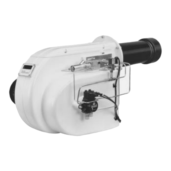
- Page 4 Fig. 2 Burner type Thermal dø Dø Eø* Type No. output kW EK 4.100 L-ZA 360–1070 240–300* BN19787/89 EK 4.160 L-ZA 580–1660 BN19787/89 Customized designs and voltages on request. * Long holes in burner connecting flange, graduated circle from … to …...
- Page 5 Burner Functions Functional Description Functional Diagram Starting function Switching over to full load The automatic burner control unit auto- If required by the system, the automatic matically starts the burner when heat is burner control unit switches the burner required by the system. to full load.
- Page 6 Burner functions Functional sequence of burner control units LAL 1... The burner control units LAL 1... are designed for controlling and monitoring burners with multi-stage or modulating control systems. For a detailed functio- nal description of the burner control units, including technical data and planning information, refer to Technical Documentation LAL 1 L&G 7153 D...
- Page 7 Installation Mounting the burner to the heat generator Zero point adjustment Electrical connection Mounting the burner to the heat Inspection glass cooling generator To keep the boiler inspection glass cool To mount the burner connecting flange and clean, a cooling line may be to the heat generator, prepare the con- connected to connection 12 R ”.
- Page 8 Installation Oil connection Oil pressure regulation Start-up Oil connection Mounting options Conversion from two-pipe to single- Hoses are used for connecting the Direct single-pipe installation pipe installation – oil pipes and the valve system. The Single pipe installation with vent The burners are delivered with the –...
- Page 9 1a Oil connection, maximum full load 2 Ignition electrode 3 Flame cup 4 Nozzle rod 5 Baffle plate holder 6 Nozzle 7 Baffle plate View Z Burner type Standard settings EK 4.100 L-ZA EK 4.160 L-ZA 09/2005 - Art. Nr. 13 019 533A...
- Page 10 Start-up Air regulation Design ”Basis” Air regulation, suction side The combustion air is adjusted on the Low load hydraulic air damper drive. · Release the lock nut 1 · Use the screw 2 to adjust the low-load air · Tighten the lock nut after adjustment.
- Page 11 Service instructions Maintenance Troubleshooting Maintenance Check for operating ability Burner installations should be serviced If a malfunction occurs, check first once a year. The combustion and whether all requirements for troublefree emission values should be checked and operation have been met. readjusted, if necessary.
- Page 12 Adresse Service-Hotline ELCO Austria GmbH 0810-400010 Aredstr.16-18 2544 Leobersdorf ELCO Belgium n.v./s.a. 02-4631902 Pontbeeklaan-53 1731 Zellik ELCOTHERM AG Sarganserstrasse 100 0848 808 808 7324 Vilters ELCO GmbH 0180-3526180 Dreieichstr.10 64546 Mörfelden-Walldorf ELCO France 18 rue des Buchillons 0450877624 74106 Annemasse ELCO-Rendamax B.V.
Need help?
Do you have a question about the EK 4.100 L-ZA and is the answer not in the manual?
Questions and answers