Table of Contents
Advertisement
EK-TRON 5.300 G-E (72H)
EK-TRON 6.350 G-E (72H)
EK-TRON 6.400 G-E (72H)
EK-TRON 7.500 G-E (72H)
EK-TRON 7.600 G-E (72H)
Original operating instructions
For specialist installation engineers
Gas burners
cn.......................................... 420011267200
EK-TRON 5-6-7.xxx G-E
EK-TRON 5-6-7.xxx G-E
09/09/2022 - Art. Nr. 420011267100
420011267300
EK-TRON 5.300 G-E KN
EK-TRON 5.300 G-E KM
EK-TRON 5.300 G-E KL
EK-TRON 6.350 G-E KN
EK-TRON 6.350 G-E KM
EK-TRON 6.350 G-E KL
EK-TRON 6.400 G-E KN
420011xxxxx
EK-TRON 6.400 G-E KM
EK-TRON 6.400 G-E KL
EK-TRON 7.500 G-E KN
EK-TRON 7.500 G-E KM
EK-TRON 7.500 G-E KL
EK-TRON 7.600 G-E KN
EK-TRON 7.600 G-E KM
EK-TRON 7.600 G-E KL
EK-TRON 5.300 G-E KN 72H
EK-TRON 5.300 G-E KM 72H
EK-TRON 5.300 G-E KL 72H
EK-TRON 6.350 G-E KN 72H
EK-TRON 6.350 G-E KM 72H
EK-TRON 6.350 G-E KL 72H
EK-TRON 6.400 G-E KN 72H
EK-TRON 6.400 G-E KM 72H
EK-TRON 6.400 G-E KL 72H
EK-TRON 7.500 G-E KN 72H
EK-TRON 7.500 G-E KM 72H
EK-TRON 7.500 G-E KL 72H
EK-TRON 7.600 G-E KN 72H
EK-TRON 7.600 G-E KM 72H
EK-TRON 7.600 G-E KL 72H
en
3148784
3148325
3148326
3148785
3148327
3148328
3148786
3148329
3148330
3148787
3148331
3148332
3148788
3148333
3148334
3148794
3148498
3148499
3148795
3148500
3148501
3148796
3148502
3148503
3148797
3148504
3148505
3148798
3148506
3148507
Advertisement
Table of Contents

Related Manuals for elco EK-TRON 5.300 G-E


Summary of Contents for elco EK-TRON 5.300 G-E
- Page 1 EK-TRON 5.300 G-E (72H) EK-TRON 6.350 G-E (72H) EK-TRON 6.400 G-E (72H) EK-TRON 7.500 G-E (72H) EK-TRON 7.600 G-E (72H) Original operating instructions For specialist installation engineers Gas burners cn.......... 420011267200 EK-TRON 5-6-7.xxx G-E 420011267300 EK-TRON 5.300 G-E KN 3148784 EK-TRON 5.300 ...
-
Page 2: Table Of Contents
Combustion components Combustion components EK-TRON 5.300 G-E adjustment data/check ......8 Combustion components EK-TRON 6.350 - 7.500-600 G-E adjustment data/check ....9 Ignition electrodes adjustment data/check . -
Page 3: General Information
Any other type of Transportation Petroleum Gas- directive, part 2. application requires the approval of ELCO. Depending on the size and weight of - Regulations on cantonal instances The burner may only be used in accordance packaging, burners and accessories (e.g. -
Page 4: Burner Description
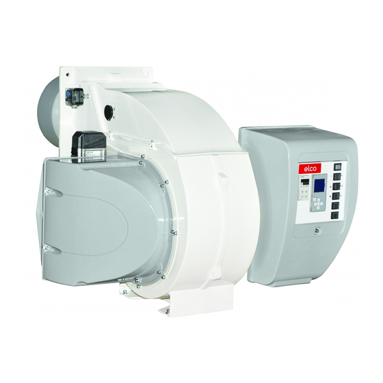
General information EK-TRON 5.300 G-E Burner description Casing Blast tube Integrated switch cabinet Burner flange Air box Hoisting rings Fastening screw/cover of switch cabinet. A4 Display F6 Air pressure switch M1 Electric motor T1 Igniter Y10 Servomotor for air Y11 Servomotor for gas flap... -
Page 5: Installation General Information Regarding Burner Installation
General information General information regarding burner installation Tightening torques During installation, commissioning and maintenance, the following torques for screw connections must be observed. Max. tightening torques for accessories system, double gas valve G1/8 G1/4 G1/2 G3/4 Siemens 3 Nm 8 Nm 15 Nm 35 Nm 7 Nm 15 Nm Dungs... -
Page 6: Boiler Lining
øG = blast tube diameter (see technical data). øa = see technical data DF = combustion chamber diameter Model T1(mm) EK-TRON 5.300 G-E > 50-100 EK-TRON 6.350 G-E > 50-100 EK-TRON 6.400 G-E > 50-100 EK-TRON 7.500 G-E > 50-100 EK-TRON 7.600 G-E... -
Page 7: Burner Installation
Installation Burner installation Assembly of the combustion head The burner is supplied in the package with the combustion head dismantled. Before fastening it to the boiler, perform the following operations: • Fasten the nosepiece in the correct position using the 2 screws A (fig.4). •... -
Page 8: Combustion Components
Installation Combustion components Combustion components EK-TRON 5.300 G-... adjustment data/check. Ionization probe Ignition electrode Firing head setting (C). Execution : • Loosen the locking screw of adjusting device V. • Move the adjusting device until the de- sired position is reached. •... -
Page 9: Combustion Components Ek-Tron 6.350 - 7.500-600 G-E Adjustment Data/Check
Installation Combustion components Combustion components EK-TRON 6.350 - 6.400 - 7.5-600 G-... adjustment data/check. 59 mm SECTION A-A (1:2) Ionization probe Elettrodo di rivelazione Ignition electrode Elettrodo di accensione 20 mm SECTION B-B Firing head setting (C). Execution : • Loosen the locking screw of adjusting device V. -
Page 10: Ignition Electrodes Adjustment Data/Check
Installation Combustion components Ignition electrodes adjustment data/check Note: If there are any ignition or flame detection problems, check the setting and dimensions of the electrodes. If the wear is too great, replace the electrodes. EK-TRON 5.300 G-... EK-TRON 6.350 G-... EK-TRON 6.400 G-... -
Page 11: Gas Train
Installation Gas train Description of gas train with VGD... Description tightening torques must be observed Gas trains with a Siemens VGD double Max. inlet pressure: 500 mbar (see chapter on Installation/tightening valve are intended for the supply, main torques). The screw connections shut-off, filtration, pressure regulation Elect. -
Page 12: Description Of Gas Train With Mbe
MBE gas train from safety principles of gas firing in heating occurs in the event of a fault, the gas Elco. Ensure during commissioning that systems. DVGW work sheets G 460 train must be equipped with a safety the max. -
Page 13: Basic Design
Installation Gas train Basic design Gas train to EN 676, low pressure. 313a 100 Burner 313a Max. gas pressure switch (72H) 120 Air flap 349 Servomotor 141 Ball valve 142 Gas filter 150 Gas control damper 151 Double gas valve with integrated regulation (Siemens VGD system shown). -
Page 14: Description Of Double Gas Valve Vgd With Skp Servomotors
Installation Gas train Description of double gas valve VGD with SKP servomotors Technical specifications VGD double gas valves with SKP actuators: Type of gas: Gasses in accordance with DVGW worksheet G 260/1, gas families 1, 2, 3 and biogas (H2S content 0.1 vol.% max.), H2 Electrical data: 220 V -15%...240 V +10%,... -
Page 15: Gas Train Components
Gas train components Gas filter Installation and mounting of the gas filter The filter must be installed in a horizontal pipe. The vertical position of the cover makes cleaning easier. Be aware of the gas flow direction (see arrow on the filter housing). In addition, it is recommended that sufficient space is provided for dismantling without obstructing the cover and for replacing... -
Page 16: Gas Pressure Switch
Gas train components Gas pressure switch Gas pressure switch GW...A5/A6 Gas pressure switch A5 Technical data: The gas pressure switch is designed to monitor the gas flow pressure. It can be Type of gas: used for monitoring either falling Gases according to DVGW Worksheet pressure (minimum) or rising pressure G 260/1, gas families 1, 2, 3. -
Page 17: Air Pressure Switch
Gas train components Air pressure switch Air pressure switch The air pressure switch is provided for N.B.(Gas and air pressure switches) monitoring the pressure of the The pressure switches must be set in combustion air fan. Pressure switch accordance with the specifications. LGW... -
Page 18: Commissioning Electronic Burner Controller
Commissioning Electronic burner controller Description The electronic burner controller is a programmable automatic firing device with an integrated electronic compound controller. There may be additional functions, depending on the equipment and model.The following burner-specific controllers are used. Burner controller BT 320 / BT 330 (72H) Manufacturer Lamtec Technical data... -
Page 19: Switch Cabinet Door Layout
Commissioning Switch cabinet door layout Manual terminal for controlling the burner control unit. Power switch on / switch off with light indicator. Auxiliary line fuse Thermal lock-out lamp Burner working lamp Power controller (option) Note: The above information is for standard equipment. -
Page 20: Servomotor Ste
Commissioning Servomotor STE The BT3xx electronic control system works with the STE4.5 numerically controlled servomotor. For monitoring the function and direction of rotation, there is a driver with digital feedback via encoder disc. Observe the commissioning procedure for BT300. The connection is documented in the burner wiring diagram. -
Page 21: Flame Sensor
Commissioning Flame sensor The flame sensor is a component of the Depending on the requirements of the In this case, no optical flame sensor is flame monitoring system. burner and fuels, the flame sensor may present. In interaction with the automatic be an optical sensor that monitors light The flame sensors used are listed in the combustion control unit, it suppresses... -
Page 22: Gas Fitting Connection Electrical Connection Checks Before Commissioning
60 Hz or in any guidelines and directives case at speeds above 2850 rpm. must be observed, as well as Elco declines all responsibility for the electrical circuit diagram damage due to operation of the supplied with the burner. -
Page 23: Gas Connection
Commissioning Gas connection Gas connection Gas properties Leak test The gas lines and trains should be Prior to any installation work make sure The fitted gas train must be leak tested installed and taken into operation in to obtain the following data from the gas on the system in accordance with accordance with the applicable supply company:... -
Page 24: Fuel-Air Compound Controller
Commissioning Fuel-air compound control ambient conditions (e.g. combustion air Fuel-air compound control This finely tuned compound control Please note: temperature and humidity, calorific system, which uniformly adjusts the fuel The gas outlet pressure (gas regulating value fluctuations, etc.) and significantly and air volume, makes it possible for pressure) must always be less than the reduce the air surplus required for... -
Page 25: Burner Power Adjusting Sequence
Commissioning Burner power adjusting sequence The burner is operated and adjusted • The burner program starts using a handheld device or a PC (serial • Adjust preventilation position of air flap Please note: interface). (and also frequency converter if If changes are made to the primary gas necessary) in accordance with pressure, test all burner power settings. -
Page 26: Inspection
Commissioning Inspection Before commissioning the system Gas commissioning for the first time, the following • Connect the test devices for the gas inspections must be carried out: head pressure on the test connection after the gas control damper and the •... -
Page 27: Preventilation
Commissioning Preventilation Preventilation: Please note: Care must be taken to ensure that the Assuming the conditions in the area or in the case of electronic boiler system is adequately the boiler unit are the same for compound controls (BT300/ preventilated. The system-specific preventilation and standard burner Etamatic), the nominal load and instructions must be observed. -
Page 28: Gas Start-Up Mode
Commissioning Gas start-up mode Gas operating mode General safety functions enabled. This brings the burner to its the installation, and may even cause Gas start-up mode As soon as the furnace is required to operating position. The controller will injury. supply heat, the burner control circuit now automatically control the burner will close and the program flow will... -
Page 29: Servicing
Servicing Maintenance Burner and boiler servicing must Work recommended as part of necessary. only be carried out by a annual burner maintenance: - Draw up a measurement report*. professionally qualified heating - Burner test run, input measurement in engineer. The system operator is the boiler room. -
Page 30: Maintenance Replacing The Control Unit
Servicing Maintenance Replacing the control unit or defective parts. Using defective or environment and to the installation, and Warning! Replace any damaged or defective damaged components may cause may even cause injury (risks of serious components! Replace safety malfunctioning and hazardous or fatal injury). - Page 31 Servicing Maintenance Checking the combustion components • Unscrew the 10 screws W, remove the housing cover. • Remove the combustion components. • Check the ignition electrodes and ignition cables, replace them if necessary (see chapter on control / maintenance, combustion components).
-
Page 32: Maintenance, Checking / Installing The Combustion Components
Servicing Maintenance Checking / installing the combustion components Filter replacement • Cleaning products based on surface check must be carried out with the • Close the main gas shutting valve, active agents are allowed. operator's agreement. and protect it to prevent from unintended opening. -
Page 33: Fan Wheel Setting
Servicing Fan wheel setting Because of its design the turbine can be fitted to the drive shaft only in a fixed position. The same position is consequently ensured every time it is assembled. There is no need for any further adjustment of the axial cover through the air conveyor. -
Page 34: Exhaust Gas Measurement
Servicing Exhaust gas measurements Exhaust gas measurement spot number in the exhaust gas must 1000 In order to ensure efficient and fault-free not be exceeded. = 1136 kW 0,88 operation, the burner must be adjusted Calculating the volumetric flow rate with reference to the specific system. -
Page 35: Diagnosing And Remedying Faults
Servicing Exhaust gas measurements Diagnosing and remedying faults Exhaust gas loss Natural Town Exhaust gas loss by way of free heat Fuel-oil EL Fuel-oil S Liquid gas will occur as a result of the temperature difference between the fuel-air mixture 0.50 0.490 0.370... -
Page 36: Faults
Servicing Diagnosing and remedying faults Faults 6. Solenoid valve fails to open 4. No response to flame by 5. Combustion components - poor Automatic firing device combustion values heavy internal oil Cause Remedy with flame sensor deposits or heavy coke deposits Replace coil or Defective coil. - Page 37 09/09/2022 - Art. Nr. 420011267100...
- Page 38 Hergestellt in der EU. Fabriqué en EU. Fabricato in EU. Angaben ohne Gewähr. Document non contractuel. Documento non contrattuale. 09/09/2022 - Art. Nr. 420011267100...
Need help?
Do you have a question about the EK-TRON 5.300 G-E and is the answer not in the manual?
Questions and answers
Здравствуйте! подскажите мин мах расход газа
@Бауржан горелки EK-TRON 6.350
The minimum and maximum gas consumption for the Elco 5.300 G-E can be derived from the nominal heat output setting and the combustion air requirement.
Given:
- Nominal heat output (QN): 3000 kW
- Combustion air requirement for natural gas E: 9.56 Nm³/Nm³
- Calorific value of natural gas E (Hi): 10.35 kWh/Nm³
Gas consumption (V) = QN / Hi
= 3000 kW / 10.35 kWh/Nm³
≈ 289.86 Nm³/h
Therefore:
- Minimum gas consumption: Not explicitly stated
- Maximum gas consumption: Approximately 290 Nm³/h for natural gas E
Minimum consumption cannot be determined from the given context.
This answer is automatically generated