Table of Contents
Advertisement
Quick Links
Advertisement
Table of Contents

Related Manuals for Arcteq AQ-101LV


Summary of Contents for Arcteq AQ-101LV
- Page 1 AQ-101(D)LV Arc flash protection unit...
-
Page 2: Table Of Contents
10.2.1. Trip relays ....................... 34 10.2.2. Binary output(s) ...................... 34 10.2.3. System failure relay....................34 10.3. Binary inputs........................34 10.4. Auxiliary voltage........................ 35 10.5. Sensors ..........................35 10.6. Disturbance tests......................36 10.7. Voltage tests........................37 10.8. Mechanical tests....................... 37 © Arcteq Relays Ltd... - Page 3 10.10. Casing and packaging ....................37 11. Or 11. Ordering inf dering informa ormation tion .............................................. 38 12. Contact and r 12. Contact and re e f f er erence inf ence informa ormation tion...................................... 40 © Arcteq Relays Ltd...
- Page 4 Nothing contained in this document shall increase the liability or extend the warranty obligations of the manufacturer Arcteq Relays Ltd. The manufacturer expressly disclaims any and all liability for any damages and/or losses caused due to a failure to comply with the instructions contained herein or caused by persons who do not fulfil the aforementioned requirements.
- Page 5 A A Q Q -101(D -101(D)L )LV V Version: 1.00 Copyright Copyright © Arcteq Relays Ltd. 2020. All rights reserved. © Arcteq Relays Ltd...
- Page 6 A A Q Q -101(D -101(D)L )LV V Version: 1.00 1. Manual revision notes R R e e vision vision 1.00 1.00 Date September 2020 Changes - The first revision of the manual. © Arcteq Relays Ltd...
-
Page 7: A 2. Abbr Bbre E Via Viations Tions
NC – normally closed NO – normally open PCB – printed circuit board QD – quenching device RF – radio frequency Rx – receiver SAS – standard arc scheme SF – system failure Tx – transceiver μP - microprocessor © Arcteq Relays Ltd... -
Page 8: General
MV use, it is designed for LV switchgears and for motor control center applications in both new and retrofitted installations. 3.1. Dimensions and installation AQ-101LV can be either door-mounted or panel-mounted in a standard 19 inch rack. The unit's dimensions are as follows: • Height: 177 mm (7.00") •... - Page 9 Figure. 3.1. - 1. Dimensions of the device (in mm). Figure. 3.1. - 2. Dimensions of the DIN rail variant (in mm). The image below presents the dimensions of the cut-out needed for mounting the unit on a panel. © Arcteq Relays Ltd...
-
Page 10: Wiring
A A Q Q -101(D -101(D)L )LV V Version: 1.00 Figure. 3.1. - 3. Cut-out for panel-mounting a unit. 3.2. Wiring © Arcteq Relays Ltd... -
Page 11: Unit Features
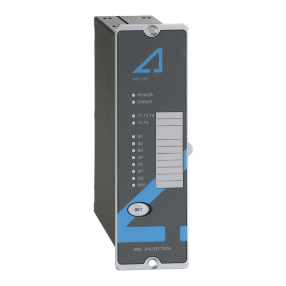
3.3. Unit features AQ-101LV is a multipurpose arc flash protection unit and can be applied to a variety of applications. It can be used on its own as a stand-alone unit, or it can be a part of a more complex arc protection system through a binary bus. - Page 12 -101(D)L )LV V Version: 1.00 • one (1) push-button. AQ-101LV comes in two variants. The AQ-101LV variant is door and panel-mounted, while the AQ-101DLV variant is mounted on a DIN rail. Figure. 3.3. - 5. Arc protection unit AQ-101LV. © Arcteq Relays Ltd...
-
Page 13: Simplified Block Diagram
Figure. 3.3. - 6. Arc protection unit AQ-101DLV. 3.4. Simplified block diagram The figure below presents the main components that can be found in both the AQ-101LV unit and the AQ-101DLV variant. Figure. 3.4. - 7. Simplified block diagram of AQ-101LV and AQ-101DLV. -
Page 14: Operation And Config Tion And Configura Uration Tion
4. Operation and configuration 4.1. LED indicator functions Both the AQ-101LV and its AQ-101DLV variant have twelve (12) indication LEDs. Apart from the "Power" and "Error" LEDs, the user can write their own identifications for each of the remaining LEDs on the text insert located in the transparent pocket next to the LEDs. -
Page 15: Push-Button (Set)
Unless the button is pressed, the latched trip relays remain active until the auxiliary power is disconnected. All LED indications also remain active even when the auxiliary power supply is disconnected unless the button is pressed. Please refer to the "Non-volatile memory" chapter for more information. © Arcteq Relays Ltd... -
Page 16: Input Connection Check
Tripping on light and overcurrent (L> + I>), (S1: L> The tripping criterion for Tripping on light only (L>). both of which are required to occur or or L> + the S1 sensor channel. simultaneously to trigger tripping. I>) © Arcteq Relays Ltd... -
Page 17: Scheme Selection
DIP switches numbered 1…4 ("Scheme selection"). For detailed instructions on each of the available schemes please refer to the AQ-SAS™ booklet (can be found at arcteq.fi/downloads/). Please note that there are four booklets: two are for schemes based on IEC standards (MV and LV versions) and the other two for schemes based on ANSI standards (MV and LV versions). - Page 18 The tripping criterion can be selected to be light only (L>) or both light and current (L> + I>). 3) Only available when the unit's configuration includes the light-only setting (i.e. when "L>" has been selected for the DIP switch SW1: 6). © Arcteq Relays Ltd...
- Page 19 2) If the blocking function (SW1: 5) is OFF, the binary input BI2 can be used to receive an external current signal. The tripping criterion can be selected to be light only (L>) or both light and current (L> + I>). © Arcteq Relays Ltd...
-
Page 20: Non-Volatile Memory
This feature is especially important if tripping causes the unit to lose its auxiliary power. The non-volatile memory does not require a power supply to maintain the information and it retains the settings and the indications permanently without power. © Arcteq Relays Ltd... -
Page 21: Ar 5. Arc Sensors C Sensors
Please remember to reattach the cover once the wires have been installed. NOTE! The AQ-01 point sensor does no not t come with a connection cable! © Arcteq Relays Ltd... -
Page 22: Arc Light And Pressure Point Sensor Aq-02
20 m, 25 m, 30 m, 35 m, 40 m). It is not recommended to cut or splice the cable on-site. However, if cutting or splicing is necessary due to the cable breaking, please contact your nearest Arcteq representative for instructions. -
Page 23: Arc Light Fiber Optic Loop Sensor Aq-07
When requested, the ends of an AQ-07 cable can be covered with black rubber to avoid light detection outside the protected zone (see the figure below). The covered area can be as large or small as necessary. For more information, please consult your nearest Arcteq representative. Figure. 5.4. - 12. AQ-07 sensor with covered ends. -
Page 24: Arc Light Fiber Optic Loop Sensor Aq-08
It is not recommended to cut or splice the cable on-site. However, if cutting or splicing is necessary due to the cable breaking, please contact your nearest Arcteq representative for instructions. The fixed light intensity threshold of an AQ-08 sensor is 8,000 lux. The sensor does not require further settings by the user. -
Page 25: Connecting Sensors
Please note that AQ-07 and AQ-08 glass fibers can be covered with additional tubing, if the fiber sensor's placing requires the blocking of unwanted light activation. For more detailed instructions on both the installation and the tubing processes, please refer to the "Connecting sensors" chapter in the AQ-0x instruction booklet (arcteq.fi/downloads). © Arcteq Relays Ltd... -
Page 26: S 6. Sy Y St Stem Self-Super Em Self-Supervision Vision
The unit goes into SF alarm mode, if a DIP switch setting is changed after the system setup procedure has been performed. However, the configured (stored) settings are still valid and the unit is still operational. © Arcteq Relays Ltd... -
Page 27: Connections
A A Q Q -101(D -101(D)L )LV V Version: 1.00 7. Connections Figure. 7. - 14. Rear terminals of AQ-101LV. © Arcteq Relays Ltd... -
Page 28: Outputs
-101(D)L )LV V Version: 1.00 Figure. 7. - 15. Front terminals of AQ-101DLV. Figure. 7. - 16. Connections of the AQ-101LV and its 101DLV variant (with SF in de-energized position). 7.1. Outputs 7.1.1. Trip relays This unit has two (2) integrated trip relays for tripping circuit breakers, namely T1 and T2. Their type is normally open (NO). -
Page 29: Binary Outputs
7.2. Inputs 7.2.1. Arc sensor channels Both AQ-101LV and AQ-101DLV have four (4) arc point sensor channels: S1, S2, S3 and S4. You can connect a maximum of three (3) arc point sensors to each channel. S5 is the optional fiber optic loop sensor channel with a transceiver (Tx) terminal and a receiver (Rx) terminal. -
Page 30: Auxiliary Voltage
80 % of the specified nominal threshold value (i.e. 19 V DC). 7.3. Auxiliary voltage The auxiliary power supply voltage is 92….265 V AC/DC. Alternatively, the optional auxiliary power supply can be of 18…72 V DC. This choice must be specified when ordering. © Arcteq Relays Ltd... -
Page 31: Testing Esting
11. Verify that no trip has occured and only the indicator LED of the sensor activation is lit. 12. If you are using the BOUT signal and have configured it to send light information, verify that it is activated. 13. Press the SET SET push button to reset all indications and latches. © Arcteq Relays Ltd... -
Page 32: Testing The Cbfp Function
If you want to have more information of these tests, please refer to the routine test reports sent with the AQ-101 unit and/or consult your nearest Arcteq representative for the type test reports. - Page 33 A A Q Q -101(D -101(D)L )LV V Version: 1.00 © Arcteq Relays Ltd...
-
Page 34: T 9. Tr R Oubleshoo Oubleshooting Ting
Check the testing equipment, especially the camera flash intensity (see the "Testing" chapter for more information). The trip relay does not operate even Check the DIP switch settings (see the "DIP switch settings" chapter for more when the sensor is activated. information). © Arcteq Relays Ltd... -
Page 35: Technic Echnical Da Al Data Ta
- make and carry for 0.5 s 30 A Breaking capacity DC* 40 W (0.36 A at 110 V DC) Contact material AgNi 90/10 *) When the time constant L/R = 40 ms. 10.3. Binary inputs Nominal threshold voltage 24 VDC © Arcteq Relays Ltd... -
Page 36: Auxiliary Voltage
IP 40 Sensor cable specification Shielded twisted pair 0.75 mm (AWG: 20) Maximum sensor cable length (per channel) 200 m Operating temperature –20…+85 ºC AQ-06 fiber optic loop sensor Material Plastic fiber Light intensity threshold 8,000 lux © Arcteq Relays Ltd... -
Page 37: Disturbance Tests
Surge (EN 61000-4-5, level 4) Between wire and earth: 4 kV, 1.2/50 µs RF electromagnetic field (EN 61000-4-3, level 3) f = 80…1,000 MHz, 10 V/m Conducted RF field (EN 61000-4-6, level 3) f = 150 kHz…80 MHz, 10 V © Arcteq Relays Ltd... -
Page 38: Voltage Tests
IP 50 - back IP 20 50 × 177 × 162 mm Device dimensions (W × H × D) 145 × 110 × 43 mm (the DIN rail variant) 0.7 kg Weight 1.0 kg (with package) © Arcteq Relays Ltd... - Page 39 A A Q Q -101(D -101(D)L )LV V Version: 1.00 11. Ordering information AQ-101LV point sensor unit (panel mounted) AQ-101DLV point sensor unit (DIN rail mounted) © Arcteq Relays Ltd...
- Page 40 AQ-0x fiber optic loop sensors Accessories Order code Description Note Manufacturer AQX099 Wall bracket For AQ-101, AQ-101S and AQ-102 units (MV and LV). Arcteq Ltd. AQX100 Wall bracket For AQ-103 and AQ-110x variants (MV and LV). Arcteq Ltd. © Arcteq Relays Ltd...
- Page 41 Manufacturer Arcteq Relays Ltd. Visiting and postal address Kvartsikatu 2 A 1 65300 Vaasa, Finland Contacts Phone: +358 10 3221 370 Fax: +358 10 3221 389 Website (general): arcteq.fi Website (technical support): support.arcteq.fi E-mail (sales): sales@arcteq.fi © Arcteq Relays Ltd...
Need help?
Do you have a question about the AQ-101LV and is the answer not in the manual?
Questions and answers