
Related Manuals for Lincoln SKF Minilube


Summary of Contents for Lincoln SKF Minilube
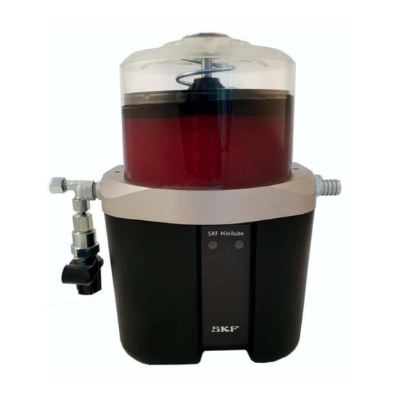
- Page 1 Assembly Instructions SKF Minilube Date: 16.6.2022 Document no.: MINILUBE Version: 2C Read this manual before installing or commissioning the product and keep it at hand for later reference!
- Page 2 Original EC Declaration of Incorporation in accordance with Directive 2006/42/EC, Appendix II Part 1 B The manufacturer hereby declares at its sole responsibility that the partly completed machinery conforms to the essential health and safety requirements of the Machinery Directive 2006/42/EC, Annex I, marked in the Annex to the EC Declaration of Incorporation as applicable and fulfilled at the time of placing on the market.
- Page 3 Appendix to Declaration of Incorporation in accordance with 2006/42/EC, Annex II, No. 1 B Description of the essential health and safety requirements according to 2006/42/EC, Annex I, which have been applied and fulfilled. Any essential health and safety requirements not listed here are not relevant to this product Table 1 Appendix to Declaration of Incorporation Valid for: MINILUBE lubrication pumps...
-
Page 4: Masthead
SKF (U.K.) Limited, 2 Canada Close, Banbury, Oxfordshire, OX16 2RT, GBR. - North America - SKF Lubrication Business Unit Lincoln Industrial 5148 North Hanley Road, St. Louis, MO. 63134 USA - South America - SKF Argentina Pte. Roca 4145, CP 2001 Rosario, Santa Fe Warranty The instructions contain no statements regarding the warranty or liability for defects. -
Page 5: Table Of Contents
Solid lubricants ..................................13 3. Overview, design & operation ..............................14 Main components ................................14 System diagram, SKF Minilube with internal ST104 control ....................15 System diagram, SKF Minilube with external ST102 control ....................16 4. MINILUBE WITH INTERNAL ST104 CONTROL ........................17 LEDs .................................... - Page 6 Disposal ..................................... 43 14. SPARE PARTS ..................................43 Minilube with internal ST104 control, spare parts ......................44 Minilube-170-ST102 pumping unit, spare parts ......................... 45 15. SKF MINILUBE WITH ST102 CONTROL CENTRE ....................... 46 16. Appendix ....................................47 China RoHS Table ................................47...
-
Page 7: Safety Alerts, Visual Presentation, And Layout
Safety alerts, visual presentation, and layout While reading these instructions, you will encounter various symbols, illustrations, and text layouts intended to help you navigate and understand the instructions. Their meaning is explained below. Safety alerts: Activities that present specific hazards (to life and limb or possible damage to property) are indicated by safety alerts. Always be sure to follow the instructions given in the safety alerts. -
Page 8: Safety Instructions
1. Safety instructions General safety instructions " Putting the products into operation or operating them without having read the instructions is prohibited. The operator must ensure that the instructions are read and understood by all persons tasked with working on the product or who supervise or instruct such persons. -
Page 9: Persons Authorized To Use The Product
Persons authorized to use the product Operator A person who is qualified by training, knowledge and experience to carry out the functions and activities related to normal operation. This includes avoiding possible hazards that may arise during operation. Specialist in mechanics Person with appropriate professional education, knowledge and experience to detect and avoid the hazards that may arise during transport, installation, start-up, operation, maintenance, repair and disassembly. -
Page 10: Notes On The Type Plate
Notes on the type plate The type plate provides important data such as the type designation, order number, and sometimes regulatory characteristics. To avoid loss of this data in case the type plate becomes illegible, it should be entered in the manual. Fig. -
Page 11: Note On China Rohs Mark
Note on China RoHS mark The China RoHS marking confirms that there is no danger to persons or the environment from the regulated substances contained within the intended period of use (number in the circle) of the product. Emergency shutdown This is done by a course of action to be defined by the operator. -
Page 12: Residual Risks
Residual risks Table 2 Residual risks Residual risk Possible in life cycle Prevention/ remedy Personal injury/ material damage A B C G H K Keep unauthorized persons away. No people may due to falling of raised parts remain under suspended loads. Lift parts with adequate lifting devices. -
Page 13: Lubricants
2. Lubricants General information Lubricants are selected specifically for the relevant application. The manufacturer or operator of the machine should ideally make the selection in consultation with the supplier of the lubricant. If you have no or little experience in selecting lubricants for lubrication systems, please contact us. -
Page 14: Overview, Design & Operation
3. Overview, design & operation The pumping unit is designed for pumping lubricant into central lubrication system. SKF Minilube is a centralised single-line lubrication system in which lubricant is pumped through piping to dosers. Dosers feed a prescribed amount of lubricant to lubrication points. -
Page 15: System Diagram, Skf Minilube With Internal St104 Control
System diagram, SKF Minilube with internal ST104 control Fig. 2 Circuit board ST104 Power supply according to 12/24 V pump model Pump unit Minilube-170 12 V or 24 V Header tube or hose Lubrication tube or hose Mounting rail B doser... -
Page 16: System Diagram, Skf Minilube With External St102 Control
System diagram, SKF Minilube with external ST102 control Fig. 3 Control centre ST102 Power supply according to 12/24 V pump model Pump unit Minilube-170-ST102 12 V or 24 V Header tube or hose Lubrication tube or hose Mounting rail B doser... -
Page 17: Minilube With Internal St104 Control
4. MINILUBE WITH INTERNAL ST104 CONTROL LEDs Red and green LEDs, visible through the pump's bottom cover, indicate the operation and the alarms of the Minilube pump. Fig. 4 Green LED Meaning Light flashes every three seconds Lubrication interval Light flashing 3 times / second Pressurisation in progress Constant light Interlocking on;... -
Page 18: Jumpers
Fig. 5 ST104 circuit board Jumpers Jumpers are identified on the timer card as A, B, C, D, and E. Jumper Jumper open: Jumper closed: Lubrication cycle schedule 1 in use Lubrication cycle schedule 2 in use Pressurization in pressure maintenance Pump stops after acknowledgement from mode pressure switch... -
Page 19: Lubrication Cycle Settings, Rotary Switch T
Lubrication cycle settings, rotary switch T Lubrication cycles are set using rotating switch T. The pressurization time is set automatically based on the selected lubrication cycle. The position of jumper A determines which of the following schedules is used: Table 3 Lubrication Cycle Schedule 1, Jumper A Open Lubrication cycle Max. -
Page 20: Test Button S
Test button S When the timer is in alarm mode, pushbutton S on the timer card can be used to acknowledge alarms and immediately pressurize the pump. NOTE An alarm will also be automatically acknowledged when the timer is switched on. When the timer is timing the lubrication cycle, pushbutton S can be used for immediate pressurization. -
Page 21: Alarm Output
4.6.2 Alarm output Connection cable wiring Alarm + Blue Alarm - The timer will introduce 12&30V to the alarm output, depending on the operating voltage, either in the alarm mode when jumper D is open or outside the alarm mode when jumper D is closed. The output can be used to control an indicator light, for example. -
Page 22: Technical Data
5. Technical data Technical specification Table 5 General technical data Max pressure 210 bar Operating pressure 24 VDC: 140 bar (pressure switch) 12 VDC 100 bar (pressure switch Ambient temperature -30 °C to +70 °C Pumping capacity 12/24 V 6.5/13 g/min Installation position vertical Sound pressure level... -
Page 23: Delivery, Returns, Storage
6. Delivery, returns, storage Delivery After receipt of the shipment, it must be inspected for any shipping damage and for completeness according to the shipping documents. Immediately inform the transport carrier of any shipping damage. The packaging material must be preserved until any discrepancies are resolved. -
Page 24: Storage Period Between 6 And 18 Months
6.5.2 Storage period between 6 and 18 months Pump " Connect the pump to its power source. " Switch on the pump and run it until about 4 ccm of lubricant comes out of every outlet. " Disconnect the pump from its power source. "... -
Page 25: Mounting
Mounting " The Minilube pump is mounted with four M8 screws that are included in the mounting kit delivered with the product. " Grade of the screws used for mounting must be a minimum of 8.8, and the torque must be a maximum of 20 Nm. "... -
Page 26: Dimensions
Dimensions Fig. 9... -
Page 27: First Start-Up
8. First start-up In order to warrant safety and function, a person assigned by the operator must carry out the following inspections. Immediately eliminate detected deficiencies. Deficiencies may be remedied by an authorized and qualified specialist only. Table 7 Inspections prior to initial start-up YES NO ¥... -
Page 28: Operation
Exercise care when dealing with lubricants. Bind and remove spilled or leaked lubricants immediately. < NOTICE Filling the SKF Minilube pump with a pneumatic filling device is not recommended, because excessively fast filling could damage the reservoir. < NOTICE Check through the pump9s transparent reservoir that there is no air in the grease being pumped to the reservoir. - Page 29 Fig. 10 The figure shows a filling device equipped with a follower plate for NLGI 1-2 greases 1. Ensure that the surroundings of the pumping unit are clean. Impurities in the system pre-vent trouble-free operation and cause damage when reaching the lubrication point. 2.
-
Page 30: Draining The Reservoir
8.4.2 Draining the reservoir If the reservoir has been filled with grease containing air and the pump fails to raise the pressure (the pressure switch fails to acknowledge), the reservoir must be drained and refilled with air-free grease. Drain the tank by detaching the pump9s bottom cover and then opening the plug in the pump section (indicated by the red arrow in the figure). -
Page 31: Bleeding The Pumping Unit
Bleeding the pumping unit If air is mixed in the lubricant, for example, during refilling, the pumping unit must be bled of air. Bleeding the pumping unit of air: Remove the pump9s bottom cover by opening the plastic mounting screw under the cover. Start the pumping unit. -
Page 32: Maintenance And Repair
9. Maintenance and repair Maintenance Regular and appropriate maintenance is a prerequisite to detect and clear faults in time. The specific time lines have to be determined, verified at regular intervals and adapted, if necessary, by the operator based on the operating conditions. If needed, copy the table for regular maintenance activities. -
Page 33: Cleaning
10. Cleaning Basics Cleaning should be carried out in accordance with the operator's own company rules, and cleaning agents and devices and the personal protective equipment to be used should likewise be selected in accordance with those rules. Only cleaning agents compatible with the materials may be used for cleaning. Completely remove any cleaning agent residue left on the product and rinse with clear water. -
Page 34: Cleaning The Filter Of The Filling Connection
Cleaning the filter of the filling connection Filter of the filling connector has to be cleaned regularly and replaced if necessary. Cleaning and replacing has to be performed when the reservoir is empty. Proceed as follows: Fig. 13 Locate the filling connector (highlighted with the red arrow). Open filling connector9s cap. - Page 35 Remove filter Clean filter with appropriate detergent and dry, e.g. with compressed air. Mount all parts again in reverse order. Tightening torques: " Filling connection (AF 27) 20 Nm ± 2.0 Nm...
-
Page 36: Faults, Causes, And Remedies
11. Faults, causes, and remedies Table 9 Fault table Fault Possible cause Remedy " Power supply to the pump is interrupted 3 Superior machine is switched off 3 Connection cable of pump is loose or defective 3 External fuse is defective Pump does not run "... -
Page 37: All The Lubrication Points Get Too Little Or Too Much Lubricant
11.1.2 All the lubrication points get too little or too much lubricant. Description of malfunction Cause of malfunction Solution All lubrication points receive too little The lubrication cycle has been set Set a shorter lubrication cycle. lubricant. too long in the timer. All the lubrication points get too The lubrication cycle has been set Set a longer lubrication cycle. -
Page 38: Changing The Pumping Element
Changing the pumping element Fig.14 To replace a pump element, proceed as follows: Locate the pumping element (highlighted with the red arrow). Unscrew the defective pump element (27 mm socket) at its hexagon out of the pump housing. - Page 39 Fill the new pumping element with grease and screw a new pump element into the pump housing (tightening torque 40 Nm + 2.0 Nm).
-
Page 40: Changing Of Line Valve
Changing the line valve Fig.15 To replace the line valve, proceed as follows: Remove pump cover and locate the line valve (highlighted with the red arrow). Remove Line valve9s nut and coil. - Page 41 Remove line valve body (24 mm wrench) and fill the new body with grease and screw it in the place. Install the coil and the other O-ring to the valve rod and then install the valve nut. Assembling in reverse procedure.
- Page 42 Changing the pressure switch Fig.16 To replace the pressure switch, proceed as follows: Remove pump cover and locate the pressure switch (highlighted with the red arrow). Unplug the pressure switch wire connectors Remove the pressure switch body (24 mm wrench) and screw in the new one (tightening torque 20 Nm).
-
Page 43: Shutdown, Disposal
13. Shutdown, disposal Temporary shutdown Temporary shutdowns should be done by a course of action to be defined by the operator. Permanent shutdown, disassembly Permanent shutdown and disassembly of the product must be planned properly by the operator and conducted in compliance with all applicable laws and regulations. -
Page 44: Minilube With Internal St104 Control, Spare Parts
Minilube with internal ST104 control, spare parts Fig. 17 16 TIMER ST104 11500750 15 LIP SEAL 11682420 14 PLASTIC RESERVOIR 11772074 13 BREATHER PLUG 11408764 12 BLEED VALVE 11390085 11 SAFETY VALVE 0.5 BAR 11770491 10 PRESSURE SWITCH 100 BAR 11601510 PRESSURE SWITCH 140 BAR 11601515... -
Page 45: Minilube-170-St102 Pumping Unit, Spare Parts
Minilube-170-ST102 pumping unit, spare parts Fig. 18 16 LOW LEVEL SWITCH 11770473 15 LIP SEAL 11682420 14 PLASTIC RESERVOIR 11772074 13 BREATHER PLUG 11408764 12 BLEED VALVE 11390085 11 SAFETY VALVE 0.5 BAR 11770491 10 PRESSURE SWITCH 100 BAR 11601510 PRESSURE SWITCH 140 BAR 11601515 COIL 12 V... -
Page 46: Skf Minilube With St102 Control Centre
15. SKF MINILUBE WITH ST102 CONTROL CENTRE See the separate ST102 instructions. -
Page 47: Appendix
16. Appendix China RoHS Table Table 10...
Need help?
Do you have a question about the SKF Minilube and is the answer not in the manual?
Questions and answers