Table of Contents
Advertisement
Quick Links
Advertisement
Table of Contents

Subscribe to Our Youtube Channel
Related Manuals for Lincoln SKF SMBM-X


Summary of Contents for Lincoln SKF SMBM-X
- Page 1 Operating Instructions Flow Limiters SMBM-X and SMBM-V EEX Created on: 05-03-2021 Document no.: 951-180-090-EN Version: Read these instructions before installation or start-up of the product and keep them readily available for later consultation.
-
Page 2: Classification As Simple Electrical Equipment In Accordance With
EU Declaration of Conformity in accordance with Directive 2014/34/EU, Annex X We hereby declare, under our sole responsibility, that the device conforms Designation: Flow limiter Type: SMBM-…EEX Item number: 5788-… / 6788-… Year of manufacture: See type plate to all relevant harmonization legislation of the European Union at the time of placing on the market. The technical documentation pursuant to: ATEX Directive 2014/34/EU Annex VIII No. -
Page 3: Explosion Protection Marking In Accordance With Directive
Explosion protection marking in accordance with Directive 2014/34/EU SMBM flow limiters without electrical attachments The ignition hazard analysis conducted in accordance with EN 80079-36 / -37 found that SKF flow limiters of the series SMBM without electrical attachments do not constitute own potential sources of ignition. They consequently do not fall under the scope of Directive 2014/34/EU and thus do not bear explosion protection marking. -
Page 4: Masthead
Warranty Masthead The instructions contain no statements regarding the warranty or liability for defects. That information can be found in our Manufacturer General Terms of Payment and Delivery. SKF Lubrication Systems Germany GmbH Email: Lubrication-germany@skf.com Training www.skf.com/lubrication We conduct detailed training in order to enable maximum safety and efficiency. -
Page 5: Table Of Contents
3.3 Plug-in nozzle table SMBM-V with D and D ....20 Table of contents 3.4 Ordering a complete flow limiter assembly ...... 21 3.5 Application ................22 Classification as simple electrical equipment in accordance with 3.6 Functional description ............22 EN 60079-14, No. - Page 6 6.7 Electrical connection of ATEX pulse generator 2340-00000091 ................ 50 6.8 Electrical connection of signal transmitter 24-1072-2125 ....................... 50 6.8.1 General information ..........50 6.8.2 Connection, signal transmitter 24-1072-2125 (connection type XS) ............50 6.9 Electrical connection of changeover valve 24-1254-3437 .......................
-
Page 7: Safety Alerts, Visual Presentation, And Layout
1. Instruction steps: These indicate a chronological sequence Safety alerts, visual of instruction steps. The numbers of the steps are in bold and are followed by a period. If a new activity follows, the presentation, and layout numbering starts again at “1.” –... -
Page 8: Safety Instructions
Responsibilities for different activities must be clearly defined 1. Safety instructions and observed. Uncertainty seriously endangers safety. Guards and safety devices must not be removed, modified, 1.1 General safety instructions nor disabled during operation and must be checked for proper function and completeness at regular intervals. -
Page 9: Foreseeable Misuse
specialist is familiar with the rules and requirements relevant to If applicable: their activity and to explosion protection, especially ATEX • Safety data sheet of the lubricant used Directives 2014/34/EU and 1999/92/EC. • Project planning documents • Supplementary information regarding special designs of the Qualified electrician pump. -
Page 10: Notes On Ce Marking
The product should be protected as much as possible from Fig. 2 humidity, dust, and vibration, and should be installed so that it is easily accessible. Ensure an adequate distance from sources of heat or cold. Any visual monitoring devices present, such as pressure gauges, min./max. -
Page 11: Expiry Of The Atex Approval
named expert and confirmed in writing. The repairs are to be • Non-observance of the permissible operating and ambient marked by a repair sign on the machine, stating the following. conditions – Date • Operation with damaged or lacking ATEX painting or ATEX –... -
Page 12: Explosion Protection Measures
1.24.2 Explosion protection measures 1.24.4 Instruction and qualification obligations • Due to a holistic assessment of the workplace, the operator ensures that the working equipment and all installation • The operator clearly determines the responsibility of materials are suitable for operation in potentially explosive personnel for operation, installation and repairs. -
Page 13: Residual Risks
1.26 Residual risks Table 1 Residual risks Residual risk Possible in lifecycle Avoidance / Remedy Personal injury / property damage due A B C G H K • Unauthorized persons must be kept away to falling of hoisted parts • Personnel are not permitted to stand under hoisted parts •... -
Page 14: Lubricants
Table 2 Residual hazards when operating in a potentially Avoidance / Remedy explosive atmosphere Generation of electrostatic charges, sparks by dropping of • Secure parts against falling parts • If necessary, cover parts to avoid sparking Introduction of catalytic, unstable, or pyrophoric •... -
Page 15: Aging Of Lubricants
The lubricant’s ignition temperature has to be at least 50 kelvin above the maximum surface temperature of the components. 2.5 Aging of lubricants In case of extended machine downtime, check before putting back into operation that the lubricant is still suitable for use in terms of chemical and physical signs of aging. -
Page 16: Overview, Functional Description
3. Overview, functional description 3.1 Type identification code of flow limiters of series SMBM 3.1.1 Definition of the type and design S M B M - V 1 1 C S 0 2 5 - E E X Component designation: SMB Flow limiter Type: Modular design... -
Page 17: Definition Of The Electrical Port And The Plug-In Nozzles
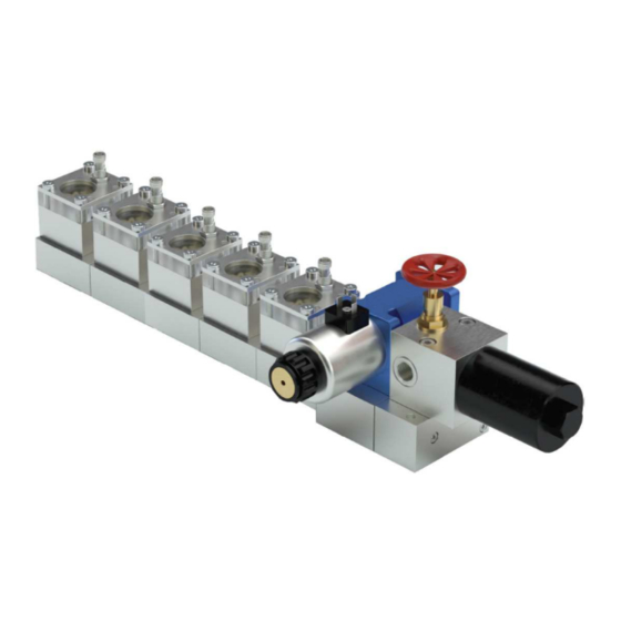
3.1.2 Definition of the electrical port and the plug-in nozzles S M B M - V 1 1 C S 0 2 5 - E E X Electrical connection: without connection cable Connection cable with angle plug Connection cable with straight plug with angle plug, without cable with straight plug, without cable Plug-in nozzle index:... - Page 18 Overview of the flow limiter SMBM-X version (Single-Flow) Fig. 3 Flow limiter SMBM-X Legend: 1 SMBM-X00 (code in the type identification code: 00) 2 SMBM-X22 (code in the type identification code: 22) 3 SMBM-X01, SMBM-X02 oder SMBM-X03 (code in the type identification code: 01, 02 or 03) 4 SMBM-X11, SMBM-X12 or SMBM-X13 (code in the type identification code: 11, 12 or 13) 5 SMBM-X51, SMBM-X52 or SMBM-X53 (code in the type identification code: 51, 52 or 53) 6 Filter with shut-off valve...
-
Page 19: Plug-In Nozzle Table Smbm-X D
Overview of the flow limiter SMBM-V version (Dual-Flow) Fig. 4 Flow limiter SMBM-V Legend: 1 SMBM-V00 (code in the type identification code: 00) 2 SMBM-V22 (code in the type identification code: 22) 3 SMBM-V01, SMBM-V02 or SMBM-V03 (code in the type identification code: 01, 02 or 03) 4 SMBM-V11, SMBM-V12 or SMBM-V13 (code in the type identification code: 11, 12 or 13) 5 SMBM-V51, SMBM-V52 or SMBM-V53 (code in the type identification code: 51, 52 or 53) 6 Changeover valve... -
Page 20: Plug-In Nozzle Table Smbm-V With D And D
Table 3 Table 3 Nominal volumetric flow Nominal volumetric flow Code [l/min] [pts/min] Item number Code [l/min] [pts/min] Item number <Content> <Content> 4.18 8.83 24-0455-2610 1.79 3.87 24-0455-2595 4.37 9.24 24-0455-2611 1.92 4.06 24-0455-2596 4.57 9.66 24-0455-2612 2.07 4.37 24-0455-2597 4.80 10.14 24-0455-2613... -
Page 21: Ordering A Complete Flow Limiter Assembly
Table 4 Nominal volumetric flow Item number Code [l/min] D [pts/min] D Plug-in nozzle D Plug-in nozzle D 1.09 : 5.00 2.30 : 10.57 24-0455-2589 24-0455-2614 1.18 : 5.37 2.49 : 11.35 24-0455-2590 24-0455-2616 1.30 : 5.77 2.75 : 12.19 24-0455-2591 24-0455-2618 1.43 : 6.22... -
Page 22: Application
Table 6 Order form for a flow limiter assembly (for examples of type identification codes, see Chapter 3.1 "Type identification code of flow limiters of series SMBM") Component Design Monitoring Electrical connection Code ATEX design (- Module Type designation (X/V/N) (../N) (XX/CA/CS/XA/XS/N) EEX/N) - Page 23 The covering of this variable restrictor D is the result of the Prerequisites equilibrium of the pressures p and p and of the spring force F To ensure impeccable functioning of the flow limiter, p must on the control piston. The influence of viscosity is only slight, always be greater than the differential pressure p plus the due to the relatively short hydraulic length which arises from...
- Page 24 Fig. 7 Functional diagram SMBM-V Table 8 Legend to Fig. 7 Item Designation Inlet volume flow (5) Q )/starting state and inlet volume flow (6) Q )/operating state Outlet volumetric flow Q Inlet pressure p upstream of D Control piston SK Plug-in nozzle D (nonadjustable restrictor) Plug-in nozzle D...
-
Page 25: Example Of A Circulating-Oil- Lubrication System With Flow Limiter Of Series Smbm-X
Fig. 8 3.7 Example of a circulating- oil- lubrication system with flow limiter of series SMBM-X See Figure 8 Before start-up of the machine, the lubricant is heated inside the oil supply unit (1). The main delivery line (2) opens when the specified lubricant temperature is reached. -
Page 26: Example Of A Circulating-Oil- Lubrication System With Flow Limiter Of Series Smbm-V
3.8 Example of a circulating- Fig. 9 oil- lubrication system with flow limiter of series SMBM-V See Figure 9 Series SMBM-V flow limiters provide an optional switchover to a lower volumetric flow to support the heating-up procedures and to avoid bearing overflows with machines that are not yet warm enough for operation. -
Page 27: Technical Data
4. Technical data 4.1 General technical data SMBM Table 11 General technical data Type 2-way flow limiter valve with fixed required value Material EN AW-6061-T651, anodized Mounting position • Without filter • With filter Vertical Flow rate 0.08 to 8.0 l/min; only up to 6.95 l/min for 333 Ipl. Operating pressure •... -
Page 28: Signal Transmitter 24-1072-2125 For Flow Indicator
4.2 Signal transmitter 24-1072-2125 for Table 13 flow indicator Pulse generator 2340-00000091 Properties/characteristics Values Table 12 <Content> Signal transmitter 24-1072-2125 Reverse voltage protection Properties/characteristics Values Short-circuit protection <Content> Power consumption Initiator pin not detected – Switching voltage (U) max. 30 V DC min. -
Page 29: Electrical Changeover Valve 24-1254-3437 For Switching
4.4 Electrical changeover valve 4.5 Oil filter 24-1254-3437 for switching from start- Table 16 up operation to normal operation Oil filter 24-0651-3041 Fig. 11 Properties/characteristics Value <Content> Type Metal grid filter Pumped medium temperature 0 to 70°C range Ambient temperature range 0 to 70°C Circuit diagram for electrical changeover valve 24-1254-3437 Material, filter flange... -
Page 30: Plug-In Nozzle Table Smbm-V With D And D
Table 17 Table 17 Nominal volumetric flow Nominal volumetric flow Code [l/min] [pts/min] Item number Code [l/min] [pts/min] Item number <Content> <Content> 1.79 3.87 24-0455-2595 4.18 8.83 24-0455-2610 1.92 4.06 24-0455-2596 4.37 9.24 24-0455-2611 2.07 4.37 24-0455-2597 4.57 9.66 24-0455-2612 2.21 4.67 24-0455-2598... -
Page 31: Calculation Of The Resulting Oil Volumetric Flow
Table 18 Nominal volumetric flow Item number Code [l/min] D [pts/min] D Plug-in nozzle D Plug-in nozzle D 0.79 : 3.79 1.67 : 8.01 24-0455-2586 24-0455-2608 0.88 : 4.37 1.86 : 9.24 24-0455-2587 24-0455-2610 0.98 : 4.57 2.07 : 9.66 24-0455-2588 24-0455-2612 1.09 : 5.00... -
Page 32: Diagram For Determination Of The Correction Factor For The Volumetric Flow Of The Oil
4.8.2 Diagram for determination of the correction factor for the volumetric flow of the oil Fig. 13 Viscosity and pressure correction Legend 1 Nozzle index 2 Viscosity 150 mm /s; Differential pressure 50 – 150 bar 3 Viscosity 300 mm /s;... -
Page 33: Determination Example
4.8.3 Determination example Given: Q = 0.69 l / min (1.46 pts / min) working viscosity v = 300 mm /s differential pressure Δp = 50 bar (e.g., system pressure 90 bar, back pressure 40 bar) 1 Preselection of the nozzle index -see diagram in Fig. -
Page 34: Delivery, Returns, Storage
5.4 Storage temperature range 5. Delivery, returns, storage For parts not filled with lubricant, the permitted storage 5.1 Delivery temperature is the same as the permitted ambient temperature range (see “Technical data”). After receipt of the shipment, it must be inspected for any 5.5 Declaration of decontamination shipping damage and for completeness according to the shipping documents. -
Page 35: Assembly
< 6. Assembly CAUTION Slipping hazard 6.1 General information Centralized lubrication systems must always be free of leaks. Leaking lubricant is hazardous. It Only qualified technical personnel may install the products creates a risk of slipping and injury. specified in the instructions. Beware of any lubricant leaking out during The product should, to the extent possible, be protected from assembly, operation, maintenance, or repair of... -
Page 36: Assembly Drawings Smbm-X
6.3 Assembly drawings SMBM-X 6.3.2 SMBM-X22 with signal transmitter 6.3.1 SMBM-X00 without gear-type flow Fig. 16 indicator, without signal transmitter Fig. 15 Flow limiter with signal transmitter, SMBM-X22 Table 20 Flow limiter, SMBM-X00 Minimum mounting dimensions, SMBM-X22 Table 19 Designation: Dimension <Content>... -
Page 37: Smbm-X01/X02/X03 With Gear-Type Flow Indicator
6.3.3 SMBM-X01/X02/X03 with gear-type 6.3.4 SMBM-X11/X12/X13 with gear-type flow indicator flow indicator and pulse generator Fig. 17 Fig. 18 Flow limiter with gear-type flow indicator SMBM-X01/X02/X03 Flow limiter with gear-type flow indicator and pulse generator, SMBM-X11/X12/X13 Table 21 Table 22 Minimum mounting dimensions SMBM-X01/02/03 Minimum mounting dimensions SMBM-X11/X12/X13 Designation:... -
Page 38: Smbm-X51/X52/X53 With Gear-Type Flow Indicator And Signal Transmitter
6.3.5 SMBM-X51/X52/X53 with gear-type flow indicator and signal transmitter 6.3.6 Filter unit for SMBM-X Fig. 19 Fig. 20 Flow limiter with gear-type flow indicator and signal Filter unit for SMBM-X transmitter, SMBM-X51/X52/X53 Table 24 Table 23 Minimum mounting dimensions, filter unit SMBM-X Minimum mounting dimensions SMBM-X51/X52/X53 Designation: Dimension... -
Page 39: Base Plates For Smbm-X
6.3.7 Base plates for SMBM-X Fig. 21 Base plates for SMBM-X Legend 1 Module 1 (base module) 2 Module 6 3 Expansion modules (2 to max. 5) 4 Connection module 5 Filter plate 6 Inlet G 1/2 7 Outlets G 3/8 8 Filter unit with shut-off valve Table 25 Attachment dimensions A/B/C/D for SMBM-X with maximum number of attached modules... - Page 40 Table 26 Weight of base plate for filter and shut-off valve 0.25 [kg] Weight [kg] 1 Module 2 Modules 3 Modules 4 Modules 5 Modules 6 Modules Total weight of SMBM-X with 2.66 4.75 6.84 8.93 11.02 13.11 number of modules NOTE The weight specifications refer to complete flow limiter assemblies without monitoring, attachments and screw unions.
-
Page 41: Assembly Drawings Smbm-V
6.4.2 SMBM-V22 with signal transmitter 6.4 Assembly drawings SMBM-V Fig. 23 6.4.1 SMBM-V00 without gear-type flow indicator, without signal transmitter Fig. 22 Flow limiter with signal transmitter, SMBM-V22 Table 28 Flow limiter, SMBM-V00 Minimum mounting dimensions SMBM-V22 Designation: Dimension Table 27 <Content>... -
Page 42: Smbm-V01/V02/V03 With Gear-Type Flow Indicator, Without Pulse Generator
6.4.3 SMBM-V01/V02/V03 with gear-type 6.4.4 SMBM-V11/V12/V13 with gear-type flow indicator, without pulse generator flow indicator and pulse generator Fig. 24 Fig. 25 Flow limiter with gear-type flow indicator SMBM-V01/V02/V03 Flow limiter with gear-type flow indicator and pulse generator, SMBM-V11/V12/V13 Table 29 Table 30 Minimum mounting dimensionsSMBM-V01/V02/V03 Minimum mounting dimensions SMBM-V11/V12/V13... -
Page 43: Smbm-V51/V52/V53 With Gear-Type Flow Indicator And Signal Transmitter
6.4.5 SMBM-V51/V52/V53 with gear-type 6.4.6 Filter unit for SMBM-V flow indicator and signal transmitter Fig. 27 Fig. 26 Filter unit for SMBM-V Flow limiter with gear-type flow indicator and signal Table 32 transmitter, SMBM-V51/V52/V53 Minimum mounting dimensions filter unit SMBM-V Table 31 Designation: Dimension... -
Page 44: Changeover Valve For Smbm-V
6.4.7 Changeover valve for SMBM-V Fig. 28 Changeover valve for SMBM-V Table 33 Minimum mounting dimensions changeover valve SMBM-V Designation: Dimension <Content> T = Width: 80 mm L = Length: 280 mm H = Height: 180 mm All further dimensions - see drawing SMBM-V00... -
Page 45: Base Plates For Smbm-V
6.4.8 Base plates for SMBM-V Fig. 29 Base plates for SMBM-V Legend 1 Module 1 (base module) 2 Module 6 3 Expansion modules (2 to max. 5) 4 Connection module 5 Filter plate 6 Inlet G 1/2 7 Outlets G 3/8 8 Changeover valve 9 Filter unit with shut-off valve 10 Valve plate... - Page 46 Table 34 Attachment dimensions A/B/C/D for SMBM-V with maximum number of attached modules Dimensions [mm] 1 Module 2 Modules 3 Modules 4 Modules 5 Modules 6 Modules 205.5 286.5 367.5 448.5 529.5 610.5 181.5 262.5 342.5 424.5 505.5 586.5 [±1] 220.5 301.5 382.5...
-
Page 47: Assembling The Flow Limiters Smbm
3. Carefully place and align the flow limiter on the flanging 6.5 Assembling the flow limiters SMBM surface and align its assembly holes with den customer- provided assembly holes. See also Fig. 30 4. Insert hexagon head bolts (2x) with washers (2x) in assembly holes and tighten them slightly. -
Page 48: Mechanical Connection Options Smbm
limiter, except when a filter unit is attached. This is not possible 6.6 Mechanical connection options SMBM with the SMBM-V flow limiter. The plug screw (6) is to be For mechanical connection options, see Figure 31and 32 tightened afterwards with a torque of 40 ±1 Nm. The outlet boreholes of the modules are located on the front The supply (1) for the flow limiters of the SMBM series is side of the flow limiter, while on the rear side the boreholes are... - Page 49 Fig. 32 Mechanical connection options SMBM-V...
-
Page 50: Electrical Connection Of Atex Pulse Generator 2340-00000091
6.7 Electrical connection of ATEX pulse 6.8 Electrical connection of signal generator 2340-00000091 transmitter 24-1072-2125 For electrical data of the ATEX pulse generator, see Chapter 4.3 6.8.1 General information < < DANGER DANGER Excessive switching voltage hazard Excessive switching voltage hazard Signal transmitters may be used only with an The pulse generator may be used only with an isolating amplifier. - Page 51 4. Connect the flexible cable leads to terminals [1] and [4] on Fig. 36 cable socket (3) in accordance with the terminal diagram (see Fig. 35). 5. Attach and tighten the connection socket (3) to the housing (4). 6. On the housing (4), use a cable gland (5) to tighten the conical ring (6) securely.
-
Page 52: Electrical Connection Of Changeover Valve 24-1254-3437
6.9 Electrical connection of changeover Table 38 valve 24-1254-3437 Spare parts/accessories For electrical data of the ATEX 3/2 changeover valve (directional solenoid valve), see Chapter 4.4 Designation Item number <Content> •Connect directional solenoid valve in accordance with the 3/2 changeover valve 24-1254-3437 terminal diagram in Figure 37. -
Page 53: First Start-Up
7. First start-up To ensure safety and functionality, the person specified by the operator is required to perform the following inspections. Any detected deficiencies must be remedied prior to initial start-up. The correction of deficiencies must be done exclusively by a specialist competent and authorized to do so. -
Page 54: Operation
8. Operation SKF products operate largely automatically. The activities required during normal operation are limited primarily to cleaning of the exterior of the product if contaminated. < IMPORTANT NOTE Avoiding malfunctions Safe operation of the flow limiters is ensured only when clean lubricating oil is being supplied. -
Page 55: Maintenance And Repair
must always be determined by the operator according to the 9. Maintenance and repair operating conditions and the local conditions and regularly reviewed and adapted where necessary. Careful and regular maintenance is required in order to detect and remedy possible faults in time. The operator must always In particular with maintenance and repair work, the following determine the specific intervals according to the operating safety measures must implemented at a minimum:... -
Page 56: Changing The Plug-In Nozzle Smbm
9.3 Changing the plug-in nozzle SMBM Fig. 38 < CAUTION Burn injury hazard Escaping oil is possibly hot < CAUTION Spring tension The control piston is under spring tension 9.3.1 Changing the plug-in nozzle SMBM-X See Figure 38 • Interrupt the oil feed to the flow limiter (1). •... - Page 57 < Fig. 39 CAUTION Burn injury hazard Escaping oil is possibly hot • Remove control piston (5) with plug-in nozzles (2/4) (D and pressure spring. < IMPORTANT NOTE Risk of mix-ups When reinstalling the plug-in nozzles, take care to ensure they are not mixed up! For plug-in nozzle selection, see Chapter 4.7 .
-
Page 58: New Mounting Or Replacement Of A Flow Limiter Module While Retaining The Base Plate Module
9.4 New mounting or replacement of a NOTE In the event that only one already mounted SMBM-X flow limiter module while retaining the module is to be replaced by a new SMBM-X module, base plate module proceed with the mounting point "Replacement of an SMBM-X module."... -
Page 59: Replacement Of An Smbm-V Module
9.4.2.3 Replacement of an SMBM-V module 9.4.2 New mounting with existing dummy module or replacement of an SMBM-V • Place new packing rings (6a) in the groove of boreholes (5) and (7). module • Carefully place the SMBM-V module (10) on the flanging area See Fig. - Page 60 • Unscrew the spacer screw (8) (2x) with a hexagon socket 9.4.3.3 Initial installation of an SMBM-V module screw key (WAF 6) and place it aside. • Using the special tool for that purpose (Part No. 2350- • Unscrew cylinder screws (9) (2x) with a hexagon socket screw 00000078, see Chapter "Spare parts"), screw check valves key and place them aside as well.
- Page 61 Fig. 40 Replacement of an SMBM module...
- Page 62 Fig. 41 Expansion of an existing assembly to include an SMBM module...
-
Page 63: Cleaning
10. Cleaning < WARNING Electric shock Perform cleaning work only on products that have been de-energized and depressurized. Do not touch cables or electrical components with wet or moist hands. Use steam-jet equipment or high- pressure cleaners only in accordance with the IP enclosure rating of the components. -
Page 64: Faults, Causes, And Remedies
< 11. Faults, causes, and WARNING System pressure remedies The described component is pressurized during operation. Depressurize the component before The following table provides an overview of possible starting maintenance work malfunctions and their causes. Contact the SKF Service department if you cannot remedy the malfunction. <... -
Page 65: System Malfunctions With Effects On The Flow Limiter
11.2 System malfunctions with effects on the flow limiter Table 47 Malfunction Cause Remedy • System pressure too low • Check the system pressure • Plug-in nozzle size too small • Check the selection of the plug-in nozzle against the selection table and insert the correct nozzle •... -
Page 66: Repairs
• Depressurize the signal transmitter (1). 12. Repairs 12.1.1 with defective signal transmitter < • Unscrew the cable socket (2) from the signal transmitter (3). WARNING • Attach box wrench (WAF 32) to the signal transmitter, detach Risk of injury the signal transmitter. -
Page 67: Mounting Or Replacement Of The Pulse Generator 2340-00000091
12.2.3 Run a function check 12.2 Mounting or replacement of the • Activate the flow limiter system. pulse generator 2340-00000091 See Fig. 43 Pulse generator 2340-00000091 NOTE Requirement: Supply voltage must be available at the pulse 12.2.1 Subsequent mounting generator, gear wheels in the gear chamber must rotate. With correct assembly and rotating gear wheels, the diode •... -
Page 68: Shutdown, Disposal
13. Shutdown, disposal 13.1 Temporary shutdown Temporary shutdown is performed by: • Switching off the main machine • Depressurizing the signal transmitter 13.2 Permanent shutdown, disassembly Permanent shutdown and disassembly of the product must be planned properly by the operator and conducted in compliance with all applicable requirements. -
Page 69: Spare Parts
14.1 Spare parts 14. Spare parts Table 48 NOTE SMBM-X Module The spare parts groups are used exclusively as replacement Designation Figure for defective parts identical in construction. Modifications to existing products by the use of spare parts are therefore not <Content>... - Page 70 Table 49 Table 51 SMBM-V Module Gasket kit for base module Item number 24-0404-2645 Designation Figure Comprised of Pcs. Part number/Type Figure <Content> <Content> SMBM-V00 Copper sealing DIN7603-A21X26-CU ring Copper sealing DIN7603-A17X21-CU ring SMBM-V22 O-Ring 12x2 WVN532-12x2 Table 52 Gasket kit for valve plate SMBM-V01/02/03 Item number 24-0404-2647 Comprised of...
- Page 71 Table 55 Table 57 Gasket kit for changeover valve Other spare parts Item number 24-0404-2639 Designation Pcs. Item number Figure Comprised of Pcs. Part number/Type Figure <Content> <Content> Stop screw with 24-1821-2040 O-ring 17x1 17, 17x1.78-N-NBR90 O--ring O-ring 9.8x1 9.81x1.5x1.78-NBR90 O-ring for stop screw 1 96-9019-0062 O-ring 21.82x3 2...
-
Page 72: Accessories
14.2 Accessories Table 59 Cable boxes with cable for ATEX inductive pulse generator Item number 2340-00000091 Designation Pcs. Item number <Content> Cable box, straight, with 5 m length 24-1882-5005 Type V1-G-N-5M-PUR Cable box, angled, with 15 m length 24-1882-5016 TYPE V1-W-N-15M-PUR Table 60 Fitting tool for check valve Item number 24-2104-2049... - Page 74 skf.com/lubrication ® SKF is a registered trademark of the SKF Group. ™ eLube is a trademark of the SKF Group. © SKF Group 2021 Reprint or reproduction of the contents of this information - even in part - is permitted only with SKF's prior written consent.
Need help?
Do you have a question about the SKF SMBM-X and is the answer not in the manual?
Questions and answers