Table of Contents
Advertisement
Quick Links
Assembly Instructions
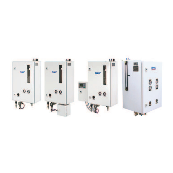
DigitalSuper in the UFD10
and UFD20 series
Minimal quantity lubrication system for internal lubrication
Created on:
21.03.2023
Document no.:
951-170-252-EN
Version:
01
Read these instructions before
installation or start-up of the
product and keep them readily
available for later consultation!
Advertisement
Table of Contents

Subscribe to Our Youtube Channel
Related Manuals for Lincoln SKF DigitalSuper UFD10 Series


Summary of Contents for Lincoln SKF DigitalSuper UFD10 Series
- Page 1 Assembly Instructions DigitalSuper in the UFD10 and UFD20 series Minimal quantity lubrication system for internal lubrication Created on: 21.03.2023 Document no.: 951-170-252-EN Version: Read these instructions before installation or start-up of the product and keep them readily available for later consultation!
- Page 2 Original EC Declaration of Incorporation in accordance with Directive 2006/42/EC, Appendix II Part 1 B The manufacturer hereby declares at its sole responsibility that the partly completed machinery conforms to the essential health and safety requirements of the Machinery Directive 2006/42/EC, Annex I, marked in the Annex to the EC Declaration of Incorporation as applicable and fulfilled at the time of placing on the market.
- Page 3 Appendix to Declaration of Incorporation in accordance with 2006/42/EC, Annex II, No. 1 B Description of the essential health and safety requirements according to 2006/42/EC, Annex I, which have been applied and fulfilled: Table 1 Appendix to Declaration of Incorporation No.: Essential health and safety requirement Applicable:...
-
Page 4: Masthead
SKF (U.K.) Limited, 2 Canada Close, Banbury, Oxfordshire, OX16 2RT, GBR. - North America - SKF Lubrication Business Unit Lincoln Industrial 5148 North Hanley Road, St. Louis, MO. 63134 USA - South America - SKF Argentina Pte. Roca 4145, CP 2001 Rosario, Santa Fe... -
Page 5: Table Of Contents
3.6.1 Minimal quantity lubrication systems with one or Table of contents two aerosol generators............22 4. Technical data ................42 Masthead ....................4 4.1 Type identification code............43 Table of contents .................. 5 4.1.1 UFD10 ................43 Safety alerts, visual presentation, and layout ......... 7 4.1.2 UFD20 ................ - Page 6 7. Setup and fieldbus configuration on the MQL system ... 61 7.1 Adjustment elements ............. 61 7.1.1 Setting options using DIP switches ......62 7.1.2 Fieldbus configuration ..........65 7.1.3 Factory settings............66 8. Communication with the machine control ....... 68 8.1 Implementation in the fieldbus system of the machine control ....................
-
Page 7: Safety Alerts, Visual Presentation, And Layout
1. Instruction steps: These indicate a chronological sequence Safety alerts, visual of instruction steps. The numbers of the steps are in bold and are followed by a period. If a new activity follows, the presentation, and layout numbering starts again at “1.” –... -
Page 8: Safety Instructions
1.3 General behaviour when handling the 1. Safety instructions product 1.1 General safety instructions • Familiarize yourself with the functions and operation of the product. The specified assembly and operating steps and their • Putting the products into operation or operating them without sequences must be observed. -
Page 9: Foreseeable Misuse
during transport, installation, start-up, operation, maintenance, 1.9 Painting plastic components and repair and disassembly. seals The painting of any plastic components and seals of the 1.6 Foreseeable misuse products described is prohibited. Completely mask or remove Any usage of the product other than as specified in this manual plastic components before painting the main machine. -
Page 10: Note On Low Voltage Directive
• 2011/65/EU Directive on the restriction of the use of certain 1.19 Assembly, maintenance, fault, hazardous substances in electrical and electronic equipment repair (RoHS II) Prior to the start of this work, all relevant persons must be notified of it. At a minimum, the following safety measures must 1.13 Note on Low Voltage Directive be taken before any work is done: The protection objectives of the Low Voltage Directive... -
Page 11: Residual Risks
1.21 Residual risks Table 2 Residual risks Residual risk Possible in lifecycle Avoidance / Remedy Personal injury / property damage due A B C G H K Unauthorized persons must be kept away. Nobody is to falling of hoisted parts allowed to be present below hoisted parts. -
Page 12: Lubricants
• The ignition temperature of the lubricant must lie at least 2. Lubricants 50 K over the maximum surface temperature of the components. 2.1 General information Lubricants are selected specifically for the respective application. The selection is made by the manufacturer or operator of the machine, preferably together with the lubricant supplier. -
Page 13: Overview, Functional Description
All SKF minimal quantity lubrication systems in the Digital 3. Overview, functional Super series have the same basic structure and work in the same way. description Using compressed air, the aerosol produced in the lubricant reservoir is transported via one or several connected aerosol 3.1 Principle of minimal quantity line(s) to the transfer point on the machine tool. -
Page 14: Minimal Quantity Lubrication
3.3.1 Minimal quantity lubrication Fig. 2 Minimal quantity lubrication Legend to Figure 2: A Aerosol line B Compressed air feed C Fieldbus D Machine control unit E Tool F Tool spindle G Ball valve nozzles. The nozzles are built into a reservoir that provides both 3.4 Main components of a UFD minimal storage of the required lubricant and also a receptacle for the quantity lubrication system... -
Page 15: Communication Interface
• The aerosol flow rate On type UFD20, the visual fill level indicators are located on • The required differential pressure in the aerosol generator the left and right sides of the control cabinet. • An optional refill pump • An additional valve which may be present, and a ball valve to 3.4.6 Main air valve (compressed air shut off the aerosol lines connection) -
Page 16: Version-Specific Components
3.5 Version-specific components Table 4 Plug Function 3.5.1 PROFIBUS communication interface Fig. 3 H1/H2 Indicates the status of the connection to the PROFIBUS H3/H4 Indicates the status of the connection to the MQL control M12x1 connection to MQL system Fastening screw Union nut M12x1 PROFIBUS connection Terminating resistor... - Page 17 3.5.1.1 Connection states Table 6 Connection states Connection to bus Connection to the MQL control Status / cause unit green LED red LED green LED red LED Power supply not present Flashing Flashing Flashing Flashing Fieldbus coupler is conducting self-test Flashing Fieldbus coupler is waiting for the MQL system to send its configuration data (number of input/output bytes, number of...
-
Page 18: Profinet Communication Interface
3.5.2 PROFINET communication interface MQL systems in the UFD10-1-2XX000 versions can be Fig. 4 operated on a PROFINET I/O controller using a gateway. The gateway is installed either in a separate switch box or in the bypass control switch box. On the PROFINET side, the gateway functions as a typical IO device. -
Page 19: Automatic Filling Pump
Table 8 LEDs for PROFIBUS DP master LED Duo LED LED color Status Meaning green Non-cyclical flashing No configuration or stack error green Cyclical flashing PROFIBUS has been configured, but bus communication is not yet approved by the application green Communication established to all slaves Cyclical flashing Communication with at least one slave interrupted... - Page 20 either back into the refill reservoir or into the customer's The control unit for the bypass valve has an information exhaust air system. display screen that provides information about the pressure During operation, the bypass valve is opened and closed ratios in the system.
-
Page 21: System Versions And Type Identification Code
3.6 System versions and type identification code Fig. 7 System overview Legend to Figure 7: System overview of Digital Super minimal quantity MQL with two aerosol generators lubrication system (MQL) UFD20-1-10X000 PROFIBUS with refill pump UFD20-1-100000 UFD20-1-101000 MQL with one aerosol generator PROFINET UFD10-1-XXX000 UFD10-1-200000... -
Page 22: Minimal Quantity Lubrication Systems With One Or Two Aerosol Generators
3.6.1 Minimal quantity lubrication systems with one or two aerosol generators 3.6.1.1 Minimal quantity lubrication systems with one aerosol generator UFD10-1-100000 Fig. 8 System design of UFD10-1-100000 Legend to Figure 8: Aerosol line B Compressed air feed Aerosol generator D MQL internal control unit Fieldbus Machine control unit Tool... - Page 23 Fig. 9 UFD10 with PROFIBUS Legend to Figure 9: Connections for aerosol lines (for up to three spindles) Pressure relief valve Plug screw for manual filling Fill level indicator Oil filter Pressure gauge for internal reservoir pressure Pressure gauge for inlet air pressure Ground connection PROFIBUS interface Lubricant drain valve...
- Page 24 UFD10-1-101000 Fig. 10 System design of UFD10-1-101000 Legend to Figure 10: Aerosol line B Compressed air feed Aerosol generator D MQL internal control unit Filling pump Refill reservoir (optional) Fieldbus H Machine control unit Tool Tool spindles Ball valve Features: •...
- Page 25 Fig. 11 UFD10 with PROFIBUS and filling pump Legend to Figure 11: Connections for aerosol lines (for up to three spindles) Pressure relief valve Control cabinet housing Fill level indicator Oil filter Pressure gauge for internal reservoir pressure Pressure gauge for inlet air pressure Ground connection Connection for filling pump PROFIBUS interface...
- Page 26 UFD10-1-110000 Fig. 12 System design of UFD10-1-110000 Legend to Figure 12: Aerosol line B Compressed air feed Aerosol generator D MQL internal control unit Fieldbus Machine control unit Tool H Tool spindles BPC Bypass Control Bypass throttle Ball valve N Ball valve Y-splitter Features: •...
- Page 27 Fig. 13 UFD10 with PROFIBUS and BypassControl Legend to Figure 13: Connections for aerosol lines (for up to three spindles) Pressure relief valve Plug screw for manual filling Control cabinet housing Fill level indicator Fine filter for compressed air Oil filter Pressure gauge for internal reservoir pressure Pressure gauge for inlet air pressure Ground connection...
- Page 28 UFD10-1-111000 Fig. 14 System design of UFD10-1-111000 Legend to Figure 14: Aerosol line B Compressed air feed Aerosol generator D MQL internal control unit Filling pump Refill reservoir (optional) Fieldbus H Machine control unit Tool Tool spindles Ball valve N Bypass throttle BPC Bypass Control R Ball valve Y-splitter...
- Page 29 Fig. 15 UFD10 with PROFIBUS, BypassControl and filling pump Legend to Figure 15: Connections for aerosol lines (for up to three spindles) Pressure relief valve Plug screw for manual filling Control cabinet housing Fill level indicator Fine filter for compressed air Oil filter Pressure gauge for internal reservoir pressure Pressure gauge for inlet air pressure...
- Page 30 UFD10-1-200000 Fig. 16 System design of UFD10-1-200000 Legend to Figure 16: Aerosol line B Compressed air feed Aerosol generator D MQL internal control unit Fieldbus Machine control unit Tool H Tool spindles Ball valve Features: • one aerosol generator • PROFINET interface...
- Page 31 Fig. 17 UFD10 with PROFINET Legend to Figure 17: Connections for aerosol lines (for up to three spindles) Pressure relief valve Plug screw for manual filling Control cabinet housing Fill level indicator Oil filter Pressure gauge for internal reservoir pressure Pressure gauge for inlet air pressure PROFINET gateway control cabinet Connection for supply voltage...
- Page 32 UFD10-1-201000 Fig. 18 System design of UFD10-1-201000 Legend to Figure 18: Aerosol line B Compressed air feed Aerosol generator D MQL internal control unit Filling pump Refill reservoir (optional) Fieldbus H Machine control unit Tool Tool spindles Ball valve Features: •...
- Page 33 Fig. 19 UFD10 with PROFINET and filling pump Legend to Figure 19: Connections for aerosol lines (for up to three spindles) Pressure relief valve Plug screw for manual filling Control cabinet housing Fill level indicator Oil filter Pressure gauge for internal reservoir pressure Pressure gauge for inlet air pressure Connection for filling pump PROFINET gateway control cabinet...
- Page 34 UFD10-1-210000 Fig. 20 System design of UFD10-1-210000 Legend to Figure 20: Aerosol line B Compressed air feed Aerosol generator D MQL internal control unit BPC Bypass Control Fieldbus Machine control unit H Tool Tool spindles Ball valve Bypass throttle N Ball valve Y-splitter Features: •...
- Page 35 Fig. 21 UFD10 with PROFINET and BypassControl Legend to Figure 21: Connections for aerosol lines (for up to three spindles) Pressure relief valve Plug screw for manual filling Control cabinet housing Fill level indicator Fine filter for compressed air Oil filter Pressure gauge for internal reservoir pressure Pressure gauge for inlet air pressure Ground connection...
- Page 36 UFD10-1-211000 Fig. 22 System design of UFD10-1-211000 Legend to Figure 22: Aerosol line B Compressed air feed Aerosol generator D MQL internal control unit Filling pump Refill reservoir (optional) Fieldbus H Machine control unit Tool Tool spindles BPC Bypass Control N Bypass throttle Ball valve R Ball valve...
- Page 37 Fig. 23 UFD10 with PROFINET, BypassControl and filling pump Legend to Figure 23: Control cabinet housing Plug screw for manual filling Pressure relief valve Control cabinet housing Fill level indicator Fine filter for compressed air Oil filter Pressure gauge for internal reservoir pressure Pressure gauge for inlet air pressure Ground connection 11 Sight glass for display panel of control unit...
- Page 38 3.6.1.2 Minimal quantity lubrication systems with two aerosol generators UFD20-1-100000 Fig. 24 System design of UFD20-1-100000 Legend to Figure 24: Aerosol line B Compressed air feed Ball valve D Tool spindles Tool PROFIBUS Machine control unit H Aerosol generator MQL internal control unit...
- Page 39 Fig. 25 UFD20 with PROFIBUS Legend to Figure 25: Connections for aerosol lines (for up to three spindles) Pressure relief valve Plug screw for manual filling Control cabinet housing Fill level indicator Pressure gauge for internal reservoir pressure Pressure gauge for inlet air pressure Oil filter Sight glass for display panel of control unit PROFIBUS interface, M12x1 plug...
- Page 40 UFD20-1-101000 Fig. 26 System design of UFD20-1-101000 Legend to Figure 26: Aerosol line B Compressed air feed Ball valve D Tool spindles Tool Filling pump Aerosol generator H PROFIBUS Refill reservoir (optional) Machine control unit MQL internal control unit...
- Page 41 Fig. 27 UFD20 with PROFIBUS Legend to Figure 27: Connections for aerosol lines (for up to three spindles) Pressure relief valve Plug screw for manual filling Control cabinet housing Fill level indicator Pressure gauge for internal reservoir pressure Pressure gauge for inlet air pressure Oil filter Sight glass for display panel of control unit PROFIBUS interface, M12x1 plug for power supply...
-
Page 42: Technical Data
4. Technical data Table 11 Characteristics / display Designation UFD10-1-XXX000 UFD20-1-XXX000 Data valid for all versions Mounting position Vertical, connections downward Reservoir capacity, utilizable 1.2 liters Permissible operating/ambient temperature + 10 °C to +40 °C Lubricant See approval list Lubricant output per outlet 3 to 400 ml/h Operating pressure, air 6 to 10 bar... -
Page 43: Type Identification Code
4.1 Type identification code 4.1.1 UFD10 Order example: UFD 10 - 1 - X X X 000 Type designation UFD Number of aerosol generators 10 = 1 aerosol generator (UFD10) Generation of manufacture 1 = 1st generation Data transmission 1 = PROFIBUS (PB) 2 = PROFINET (PN) Bypass system (BPC) 0 = without bypass control... -
Page 44: Delivery, Returns, Storage
5.5 Storage conditions for products filled 5. Delivery, returns, storage with lubricant 5.1 Delivery For products filled with lubricant, the permitted storage temperature range is: After receipt of the shipment, it must be inspected for any minimum + 5 °C [+41 °F] shipping damage and for completeness according to the maximum... -
Page 45: Assembly
• Connect the aerosol and compressed air lines 6. Assembly • Electrical connection and settings • Software configuration in the machine control unit. 6.1 General 6.3 Mechanical connection CAUTION Personal injury / property damage WARNING Injury/damage due to unqualified personnel Suspended load Assembly and connection of the system may only Risk of death from raised loads crashing... -
Page 46: Attachment Of The Mql Systems
• Lift the MQL system using a hoist and align it to the assembly 6.5.1 Attachment of the MQL systems holes • Pass the hexagon head screws (4x) with the associated NOTE washers (4x) through the mounting holes on the mounting For the corresponding overview, see section 6.6 Installation plate and apply the screws to the M8 thread on the mounting dimensions and minimum mounting dimensions... -
Page 47: Mms Ufd10-1-200000 Und Ufd10-1-201000
6.6.2 MMS UFD10-1-200000 und UFD10-1-201000 Fig. 30 UFD10-1-1-200000 und UFD10-1-201000 Legend to Figure 30: Minimum mounting dimensions/clearance Height 1000 mm Width 400 mm Depth 650 mm Drilling template... -
Page 48: Mms Ufd10-1-110000 Und Ufd10-1-111000
6.6.3 MMS UFD10-1-110000 und UFD10-1-111000 Fig. 31 UFD10-1-110000 / UFD10-1-111000 Legend to Figure 31: Minimum mounting dimensions/clearance Height 1000 mm Width 700 mm Depth 650 mm Drilling template... -
Page 49: Mms Ufd10-1-210000 Und Ufd10-1-211000
6.6.4 MMS UFD10-1-210000 und UFD10-1-211000 Fig. 32 UFD10-1-210000 / UFD10-1-211000 Legend to Figure 32: Minimum mounting dimensions/clearance Height 1000 mm Width 700 mm Depth 650 mm Drilling template... -
Page 50: Mms Ufd20-1-100000 Und Ufd20-1-101000
6.6.5 MMS UFD20-1-100000 und UFD20-1-101000 Fig. 33 UFD20-1-1-100000 und UFD20-1-101000 Legend to Figure 33: Minimum mounting dimensions/clearance Height 1000 mm Width 450 mm Depth 782 mm Drilling template... -
Page 51: Connection Of Aerosol Lines
• All joints should have a smooth surface and have no holes or 6.7 Connection of aerosol lines projecting edges. This applies especially to the transition area 6.7.1 General instructions for the connection between the tool and toolholder. • The aerosol lines should be laid so that they are subject to of the aerosol lines few vibrations. -
Page 52: Connecting The Aerosol Lines To An Mql System With Bypass Control
4. Using the accompanying electrical cable, connect the bypass NOTICE valve (6) to the bypass control (sections 7. Setup and fieldbus Functional failure configuration on the MQL systemand 8. Communication with Faults or functional failure due to check valves the machine control). Check valves in rotary leadthroughs and spindles must be removed because they cause faults and functional failure of 2. - Page 53 3. Connect the remaining piece of the aerosol line (Fig. 35/2) to the outlet of the aerosol monitor (Fig. 35/1) and to the ball valve provided by the customer (Fig. 35/4). 6.7.3.1 Connection overview of bypass system Fig. 36 Connecting the bypass system Legend to Figure 36: Y-splitter Aerosol line...
-
Page 54: Electrical Connection
4 Communication connection (IN) 6.8 Electrical connection 5 Plug connector for PROFIBUS DP fieldbus coupler 6 PC communication connection 7 Operating voltage connection 24 VDC CAUTION Personnel not properly qualified Figure 37 shows the electric connections arranged at the base Danger due to personnel not being properly of the control cabinet housing. -
Page 55: Possible Connections By The Customer With Ufd10- 1-2Xx000 With Profinet
Additional valve and ball valve (see also Fig. 37/1 and 2) Fieldbus coupler for PROFIBUS connection (see also Fig. 37/5) Fig. 39 Fig. 40 Additional valve and ball valve Fieldbus coupler PROFIBUS connection Legend to Figure 39: A Connection for additional valve B-coded plug contact (on the unit), M12x1, 5-pin B Connection for ball valve Table 16... -
Page 56: Possible Connections By The Customer With Ufd10- 1-20000 / Ufd10-1-201000
Connection of operating voltage (see also Fig. 37/7) Fig. 43 Fig. 41 Operating voltage connection PROFINET connection A-coded plug contact (on the unit), M12x1, 5-pin D-coded socket contact (on the unit), M12x1, 4-pin Table 17 Table 19 Assignment - Figure 41 Assignment for PROFINET - Figure 43 Plug contact Assignment... -
Page 57: Possible Connections By The Customer With Ufd10- 1-110000 / Ufd10-1-111000
Table 22 Table 20 Assignment for bypass control - Figure 45 Assignment for PROFINET - Figure 44 Socket contact Assignment Wire colors Socket contact Assignment Wire colors Pin 1 brown Pin 1 yellow Pin 2 white Pin 2 white Pin 3 0 V (GND) blue Pin 3... -
Page 58: Possible Connections By The Customer With Ufd10- 1-210000 / Ufd10-1-211000
6.8.6 Possible connections by the customer Table 25 with UFD10-1-210000 / UFD10-1-211000 Assignment for PROFINET - Figure 46 Fig. 46 Socket contact Assignment Wire colors Pin 1 yellow Pin 2 white Pin 3 Orange Pin 4 blue Table 26 Assignment for bypass control - Figure 46 Socket contact Assignment Wire colors... -
Page 59: Possible Connections By The Customer To An Optional Skf Aerosol Monitor (Am1000)
Table 28 Connecting element Notes SKF accessory Order No. Included Connection for PROFIBUS See section 3.5 Version-specific PROFIBUS-DP UFZ.0255 DP fieldbus coupler, M12x1 components fieldbus plug SKF data connection, M12x1 For interconnection of multiple control SKF data UFZ.0260 socket units; allows control of multiple MQL connection cable systems via a single PROFIBUS connection. -
Page 60: Pneumatic Connection
The MQL system can operate with an inlet air pressure as low 6.9 Pneumatic connection as 4 bar. The system reaches its peak performance with an inlet air pressure ≥ 6 bar. CAUTION System pressure Table 29 Excessive inlet air pressure poses a risk of injury Requirements for compressed air The MQL system must be operated only at a... -
Page 61: Setup And Fieldbus Configuration On The Mql System
7. Setup and fieldbus Legend to Figure 49: 1 DIP switch, 8-position configuration on the MQL 2 LED display, 4-digit 3 Decimal rotary switches system When the MQL systems are delivered from the factory, they 7.1 Adjustment elements already have typical configuration settings, so only a few configuration steps are needed to make them ready for operation. -
Page 62: Setting Options Using Dip Switches
7.1.1 Setting options using DIP switches Table 30 DIP switch Function Setting AM1000 aerosol monitor DIP 8 ON Available (connected) OFF Unavailable (not connected) Process image DIP 7 ON With analog value transmission OFF Without analog value transmission Minimal quantity lubrication system DIP 6 ON UFD20-02X OFF UFD10-02X... - Page 63 Operating mode 3: automatic start of the refill pump when the Process image used (DIP switch 7) level drops to "minimum". NOTE The refill pump is activated automatically by the MQL control See also section 7.1.1 Setting options using DIP switches unit.
- Page 64 Fig. 50 Digital Super UFD20 with AM1000, electrical wiring and settings of DIP and rotary switches Legend to Figure 50: A Digital Super UFD10-1-XXX000 B Digital Super UFD20-1-XXX000 NOTE To connect an aerosol monitor to the MQL system, see the operating instructions for the AM1000 aerosol monitor Table 31 Setting options for DIP switches Control unit 1...
-
Page 65: Fieldbus Configuration
Table 31 Setting options for DIP switches Control unit 1 Control unit 2 MQL version DIP switch Hex switch DIP switch Hex switch UFD10-1-210000 Not present Not present UFD10-1-201000 Not present Not present UFD10-1-211000 Not present Not present UFD20-1-100000 UFD20-1-101000 7.1.2.1 Systems with PROFIBUS 7.1.2 Fieldbus configuration Fig. -
Page 66: Factory Settings
1 M12x1 connection to MQL system (factory setting). 2 Fastening screw If the MQL system is the last node on the PROFIBUS, the 3 M12x1 PROFIBUS connection accompanying terminating resistor must be connected to the 4 Terminating resistor fieldbus plug (Fig. 52). 5 M12x1 connection for terminating resistor 7.1.2.2 Systems with PROFINET All MQL versions with a PROFIBUS interface are connected to... - Page 67 Table 32 Factory settings of the Digital Super systems Control unit 1 Control unit 2 MQL version DIP switch Hex switch DIP switch Hex switch UFD10-1-211000 Not present Not present UFD20-1-100000 UFD20-1-101000...
-
Page 68: Communication With The Machine Control
Observe the following instructions: 8. Communication with the • If the optional AM1000 aerosol monitor is operated on the MQL system, either UFD10A or UFD20A should generally be machine control selected so that its measurement data can be transmitted to the machine tool. -
Page 69: Assignment Of The Input Bytes (Ib0 And Ib1) - Data From Mql System To Machine
GSD/GSDML files provide the corresponding configurations. The input words provide the machine tool control with Sections 8.2.1 Assignment of the input bytes (IB0 and IB1) - digitized measurement values in the form of 16 bit integer data from MQL system to machine, 8.2.2 Assignment of the values from the MQL system (e.g., the amount of inlet pressure) input words , and 8.2.3 Assignment of the output bytes (OB0 or the values of optional components connected (e.g., AM1000). -
Page 70: Assignment Of The Input Words
8.2.1.3 Information on the inlet pressure (IB0, bit5) • DIP switches 2 and 3 on the control unit are both briefly set to "ON" A pressure sensor measures the inlet air pressure applied to the • The control unit is briefly disconnected from the power supply MQL system when the main air valve is open. -
Page 71: Assignment Of The Output Bytes (Ob0 And Ob1)
Assignment of the input words when using the process image with analog value transmission Input words Value/signal Value range Unit Explanation Word Relative address Relative value, transmitted from Aerosol density 0 ... 1000 aerosol monitor to MQL system Approximate value determined Air flow rate 0-600 Nl/min... - Page 72 8.2.3.1 Controlling a refill device (OB0, bit0) The main air valve must not be used to interrupt aerosol generation. To interrupt aerosol generation and the aerosol MQL systems with an integrated refill pump (UFDX0-1-XX100) flow (during a tool change, for example), routine number "0" can be configured for the refill pump to be started either must be called: see section 8.2.3 Assignment of the output automatically by the MQL system control or by a command...
- Page 73 Table 34 Lube routines Routine no. Output byte 1 Air volume flow Lubricant flow [ml/h] Cooling duct diameter of tool [mm] 1 duct 2 ducts 25 % 50 % 100 % 2x0,7 2x0,7 1x1.5 2x1.1 1x1.5 2x1.4 1x2.5 2x1.8 2x2.1 1x3.5 2x2.5 Controlled...
-
Page 74: First Start-Up
Fig. 53 9. First start-up 9.1 Initial filling CAUTION System pressure Danger from pressurized system The aerosol generator must be depressurized before filling. NOTICE Lubricant Damage from incorrect lubricant Only lubricants provided by SKF may be used. SKF will not accept claims for damages resulting from the use of lubricants other than those approved in writing by SKF. -
Page 75: Manual Filling
9.3 Automatic filling NOTE • Wait until the pressure has been released via the aerosol Optionally, the MQL systems can be filled automatically. outlets. For this purpose, the customer's supply line must be • Operate the pressure limiting valve to check that the connected to the port of the filling pump (Fig. -
Page 76: Operation
10. Operation SKF products operate largely automatically. The activities required during normal operation are limited primarily to inspection of the fill level, timely refilling of lubricant, and cleaning the exterior of the product if contaminated. 10.1 Top up lubricant For a description, see the corresponding section 11.2 Refilling lubricant in systems with manual lubricant refill... -
Page 77: Maintenance And Repair
SKF Lubrication Systems Germany GmbH MQL systems are 11. Maintenance and repair low-maintenance. All connections and fittings must be regularly inspected for proper seating to ensure proper function and to 11.1 General prevent hazards. Dismantling of the product or individual parts of the product within the statutory warranty period is prohibited and voids any WARNING claims. - Page 78 Fig. 54 Main compressed air valve Legend to Figure 54: Aerosol outlets Pressure relief valve Filler screw Coupling piece Drain valve Slider on main compressed air valve Control cabinet door Aerosol generator Main compressed air valve Slider position (Fig. 54/4) at top = main compressed air supply switched on Slider position (Fig.
-
Page 79: Draining Lubricant
NOTICE NOTE Loss of oil Check whether the pressure has been completely released Damage if filling port not closed by briefly actuating the pressure relief valve (2). Close the fillport tightly after filling. Ensure that the sealing ring is in the correct position beforehand. 6. -
Page 80: Cleaning
12.3 Interior cleaning 12. Cleaning The interior normally does not need to be cleaned. The interior of the product must be cleaned if incorrect or WARNING contaminated lubricant is accidentally filled. Electric shock Please contact SKF Customer Service. Performing work on products that have not been de-energized may result in serious injury or death 12.4 Cleaning the fine compressed air... -
Page 81: Cleaning The Oil Filter
3 Aerosol generator 4 Filter strainer NOTE 5 Filter housing Observe the legal regulations for disposal of lubricants 6 Fine filter for compressed air / filter holder 7 Main air valve 8 Coupling piece 2. Unscrew and remove the filter housing (Fig. 55/5) (hexagon, SW 13 mm) by turning counterclockwise. -
Page 82: Faults, Causes, And Remedies
13. Faults, causes, and 13.1 Prior to beginning troubleshooting remedies The following requirements must be met so that the MQL system functions smoothly: CAUTION • The system is correctly connected. System pressure • Compressed air with an adequate primary air pressure (at Hydraulic pressure least 4 bar) is supplied. -
Page 83: Faults When Using Mql Systems With Bypass Control
Table 35 Fault Cause Remedy Use of lubricants not approved by SKF. Use only lubricants which have been approved by SKF. The system does not produce any The system is not activated correctly by the Check the connection plug and the signal aerosol machine's control unit. -
Page 84: Fault Notification Via The Led Display
Table 36 Fault Cause Remedy Quantity of aero sol on the tool is insuffi cient Incorrect routine number was set Use routine number 50 Bypass valve does not cycle during Unsuitable ratio of cooling duct diameter to bypass Record the usage parameters and the machining process throttle diameter contact the SKF Service department... -
Page 85: Replacing Defective Fuses
13.5 Replacing defective fuses Fig. 56 Fuses Legend to Figure 56: MQL-DigitalSuper F = T4A Bypass valve (Q1) F = T1A Bypass, control unit F = T1A The fuses are installed in the MQL control cabinets. UFD10-1-X1X000 In the case of this MQL system, the power supply and the fuses are installed in the PROFINET control cabinet. -
Page 86: Repairs
14. Repairs < WARNING Risk of injury At a minimum, the following safety measures must be taken before any repairs: • Unauthorized persons must be kept away • Mark and secure the work area • Depressurize the product • Isolate the product, and lock and tag it out •... -
Page 87: Spare Parts
16. Spare parts Spare parts may be used exclusively for replacement of identical defective parts. Modifications with spare parts on existing products are not allowed. Table 38 Order No. Designation UFD.U41-000 Control unit, complete UFD.U11-004 Reservoir, complete UFD.U20-007 Control unit, complete FLM12-S58+924 FLP unit, 24 VDC UFD.U50-002... -
Page 88: Appendix
17. Appendix 17.1 Accessories Table 39 Designation Order No. Ball valve 2/2-way 100 bar UFZ.U00-128 Ball valve 3/2-way 100 bar For aerosol / cooling lubricant switchover UFZ.U00-041 Aerosol hose ø 12 mm running meter UFZ.0027 Aerosol nozzle, complete, for external Incl. -
Page 89: China Rohs Table
Table 41 Cable colors in accordance with IEC 60757 Black Green White Pink Brown Yellow Orange Turquoise Blue Violet Gray GNYE Green/Yellow RDWH Red/White Gold Silver Not all cable colors need to be used in the terminal diagrams. 17.3 China RoHS Table Table 42... - Page 96 ® SKF and Lincoln are registered trademarks of the SKF Group. ™ eLube is a trademark of the SKF Group. © SKF Group 2023 Reprint or reproduction of the contents of this information - even in part - is permitted only with SKF's prior written consent.
Need help?
Do you have a question about the SKF DigitalSuper UFD10 Series and is the answer not in the manual?
Questions and answers