Advertisement
Quick Links
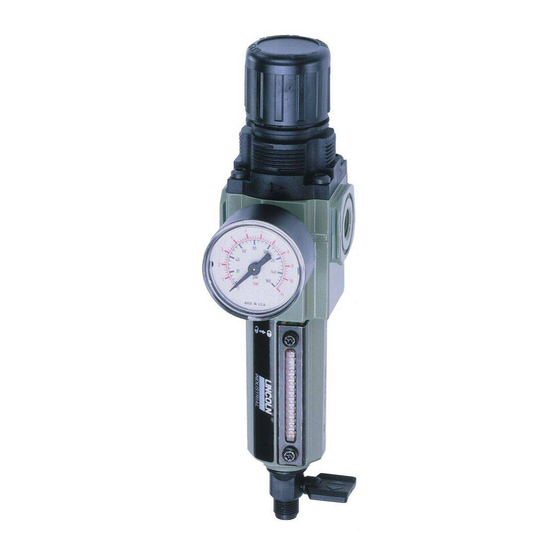
602134 - 1/4" PORTS
602136 - 3/8" PORTS
JAN - 04
TECHNICAL DATA
Fluid: Compressed air
Maximum Pressure: 250 psig (17 bar)
Operating Temperature: 0° to+150°F
(-20° to +65°C)*
*Air supply must be dry enough to
avoid ice formation at temperatures
below +35'F (+2°C).
Main ports: 1/4" PTF or 3/4" PTF
Gauge ports: 1/8" PTF
Outlet pressure adjustment range: 5 to
150 psig (0.3 to 10 bar)**
**Outlet pressure can be adjusted to
pressures in excess of, and less
than, those specified. Do not use
these units to control pressures out-
side of the specified ranges.
Filter element rating: 40µm
Materials:
Body: Zinc
Bonnet: Acetal
Valve: Brass
Bowl: Zinc
Liquid level indicator lens:
Transparent nylon
Element: Sintered polypropylene
plastic
Elastomers: Neoprene and Nitrile
REPLACEMENT ITEMS AND
ACCESSORIES
Service Kit (13, 50, 56,
57, 58, 59).................................247882
Liquid level lens kit
(46, 48, 49, 50).........................247875
Filter element, 40µm (53).........247892
Manual drain (40, 41, 42)...........247893
Tamper resistant cover............... 247777
PANEL MOUNTING DIMENSIONS
Panel mounting hole diameter: 1.57"
(40 mm)
Panel thickness: 0.06" to 0.16" (2 to 4
mm)
INSTALLATION
1. Install unit vertically in air line -
• upstream of lubricators and
cycling valves,
• with air flow in direction of arrow
on body,
• as close as possible to the device
One Lincoln Way
St. Louis, MO 63120-1578 USA
Phone +1.314.679.4200
Fax +1.800.424.5359
MODEL 602134, 602136
Air Line Filter/Regulator
being serviced.
2 Connect piping to proper ports
using pipe thread sealant on male
threads only. Do not allow sealant
to enter interior of unit.
3. Turn bowl fully clockwise into body
before pressurizing.
4. Install a pressure gauge or plug the
gauge ports. Gauge ports can also
be used as additional outlets for
regulated air.
5. Manual drain is ported 1/8-27 and
1/8-28 pipe thread.
ADJUSTMENT
1. Turn adjustment clockwise to
increase pressure setting. Turn
adjustment counterclockwise to
decrease pressure setting.
2. Always approach the desired
pressure from a lower pressure.
When reducing from a higher to a
lower setting, first reduce to some
pressure less than that desired,
then bring up to the desired pres-
sure.
3. Push knob down to lock pressure
setting. Pull knob up to release.
Install tamper resistant cover (see
Replacement Items and Accesso-
ries) to make setting tamper
resistant.
SERVICING
1. Open manual drain to expel accu-
mulated liquids. Keep liquids below
baffle (52).
2. Clean or replace filter element (53)
when dirty.
DISASSEMBLY
1. Shut off inlet pressure. Reduce
pressure in inlet and outlet lines to
zero. Turn adjustment (1) fully
counterclockwise.
2. Remove bowl - push into body and
turn counterclockwise.
3. Disassemble in general accor-
dance with the item numbers on
exploded view. Disassemble and
replace drain (40, 41, 42) only if it
© Copyright 2004
Printed in USA
Web site:
www.lincolnindustrial.com
- G10
Section
- 29A
Page
Form 403418
Advertisement

Related Manuals for Lincoln 602134


Summary of Contents for Lincoln 602134
- Page 1 MODEL 602134, 602136 Air Line Filter/Regulator 602134 - 1/4" PORTS TECHNICAL DATA being serviced. 602136 - 3/8" PORTS Fluid: Compressed air 2 Connect piping to proper ports Maximum Pressure: 250 psig (17 bar) using pipe thread sealant on male Operating Temperature: 0° to+150°F threads only.
- Page 2 Additionally, in years two (2) and three (3) the warranty on this equipment is limited to repair with Lincoln paying parts and labor only. In years four (4) and five (5), the warranty on this equipment is limited to repair with Lincoln paying for parts only.
Need help?
Do you have a question about the 602134 and is the answer not in the manual?
Questions and answers