
Related Manuals for Lincoln SKF VectoLub VE1B unit


Summary of Contents for Lincoln SKF VectoLub VE1B unit
- Page 1 Assembly Instructions VE1B unit SKF VectoLub Date issue: 08-2022 Document No.: 951-130-441 Version : Read manual prior to installation or use of this product. Keep manual nearby for future reference.
- Page 2 Original EC Declaration of Incorporation in accordance with Directive 2006/42/EC, Appendix II Part 1 B The manufacturer hereby declares at its sole responsibility that the partly completed machinery conforms to the essential health and safety requirements of the Machinery Directive 2006/42/EC, Annex I, marked in the Annex to the EC Declaration of Incorporation as applicable and fulfilled at the time of placing on the market.
- Page 3 Appendix to Declaration of Incorporation in accordance with 2006/42/EC, Annex II, No. 1 B Description of the essential health and safety requirements according to 2006/42/EC, Annex I, which have been applied and fulfilled: Table 1 Appendix to Declaration of Incorporation No.: Essential health and safety requirement Applicable:...
- Page 4 Table 1 Appendix to Declaration of Incorporation No.: Essential health and safety requirement Applicable: Fulfilled: 2012-05-01 Laser radiation 2013-05-01 Emissions of hazardous materials and substances Partly 2014-05-01 Risk of being trapped in a machine 2015-05-01 Risk of slipping, tripping or falling 2016-05-01 Lightning Maintenance 1.6.1...
-
Page 5: Imprint
Motzener Straße 35/37 12277 Berlin - North America - Germany SKF Lubrication Business Unit Tel. +49 (0)30 72002-0 Lincoln Industrial Fax +49 (0)30 72002-111 5148 North Hanley Road, St. Louis, MO. 63134 USA Walldorf Plant Heinrich-Hertz-Straße 2-8 - South America - 69190 Walldorf SKF Argentina Pte. -
Page 6: Table Of Contents
7. First start-up ................23 Table of contents 7.1 Inspections prior to commissioning ........23 7.2 Bleeding and commissioning ..........23 Imprint ....................5 7.2.1 Commissioning ............23 Manufacturer ..................5 7.2.2 Bleeding the micropump ......... 24 Service ....................5 7.2.3 Switching out a nozzle .......... -
Page 7: Safety Alerts, Visual Presentation, And Layout
1. Instruction steps: These indicate a chronological sequence Safety alerts, visual of instruction steps. The numbers of the steps are in bold and are followed by a period. If a new activity follows, the presentation, and layout numbering starts again at <1.= –... -
Page 8: Safety Instructions
1.3 General behaviour when handling the 1. Safety instructions product 1.1 General safety instructions • Familiarize yourself with the functions and operation of the product. The specified assembly and operating steps and their • Putting the products into operation or operating them without sequences must be observed. -
Page 9: Foreseeable Misuse
• Alterations to the control circuit board beyond adjustment of lubrication times and interval times or replacement in case of 1.6 Foreseeable misuse defect • Alterations to the power supply board beyond replacement in Any usage of the product other than as specified in this manual case of defect is strictly prohibited. -
Page 10: First Start-Up, Daily Start-Up
• Dry any wet, slippery surfaces or cover them appropriately • Cover hot or cold surfaces appropriately Where applicable: • Depressurize • Isolate, lock and tag out • Check to ensure live voltage is no longer present • Ground and short-circuit The product should be protected as much as possible from humidity, dust, and vibration, and should be installed so that it is easily accessible. -
Page 11: Lubricants
• The ignition temperature of the lubricant must lie at least 2. Lubricants 50 K over the maximum surface temperature of the components. 2.1 General information Lubricants are selected specifically for the respective application. The selection is made by the manufacturer or operator of the machine, preferably together with the lubricant supplier. -
Page 12: Overview, Functional Description
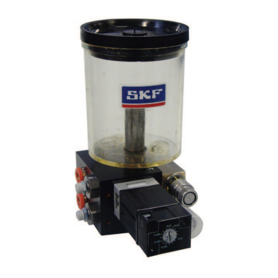
3 Micropump, setting with thumb wheel 3. Overview, functional 4 Carrier air pressure regulator 5 Air inlet port (beneath) description 6 Solenoid valve 7 Micropump, setting with metering rings 3.1 Description 8 Lubricant inlet port 9 Coaxial outlet 3.1.1 General The VE1B unit is a compact unit. - Page 13 Fig. 1 VE1B unit...
-
Page 14: Function
carrier air. The low-pressure carrier air and oil are 3.2 Function simultaneously transported under pressure via the coaxial hose to the nozzle. The carrier air is swirled in the nozzle. As a result, When the VE1B unit is switched on, it is supplied with the metered quantity of oil is broken down into microdroplets, compressed air (5 to 8 bar) and with oil (0,1 to 0,5 bar). -
Page 15: Technical Data
4. Technical data Table 2 Technical data VE1B system VE1B unit Number of outlets 1 to 4 Min. air inlet 400 Nl/min, dry and filtered air (5 ¿m) Air inlet pressure 5 to 8 bar Micropump flow rate 3, 5, 10, 15, 20 and 30 mm /stroke (small flow, metering rings) 7 to 30 mm / stroke (small flow, thumb wheel) - Page 16 Fig. 3 VE1B unit dimensions Table 3 VE1B dimensions Number of micropumps <Content>...
-
Page 17: Delivery, Returns, Storage
5.4 Storage temperature range 5. Delivery, returns, storage For parts not filled with lubricant, the permitted storage 5.1 Delivery temperature is the same as the permitted ambient temperature range (see <Technical data=). After receipt of the shipment, it must be inspected for any shipping damage and for completeness according to the shipping documents. -
Page 18: Assembly
Fig. 5 6. Assembly < CAUTION System part list Check the integrity of the delivery before starting installation works. VE1B unit mounting rail 6.1 General 6.3 Inlet connection The product described in the mounting instructions may only be installed, operated, maintained, and repaired by qualified 6.3.1 Oil inlet connection experts. -
Page 19: Pneumatic Connection
6.3.2 Pneumatic connection The lubrication unit must be connected to the compressed air network. The compressed air quality must comply with purity class 5 defined by DIN ISO 8573-1: • Maximum particle size: 40 ¿m " Maximum particle density: 10 mg/m "... -
Page 20: Outlet Connection
Fig. 6 6.4 Outlet connection 5 6 5 6.4.1 Connection coaxial line / outlet port /CAUTION The coaxial line may be only connected by authorized and trained specialists. CAUTION The coaxial line has first to be connected to the outlet port of the lubrication unit and then to the nozzle. - Page 21 CAUTION The length of the coaxial line between the outlet port of the When mounting or dismounting, never twist, bend module and the nozzle has to be between 1 and 5 m. For or crush the coaxial tube. greater length, please contact the SKF service center. 1.
-
Page 22: Electrical Connection
Fig. 8 6.5 Electrical connection WARNING Electrical connection Only qualified, instructed specialists who are authorized by the operator may install the electrical connections for the lubrication unit. The connection conditions and the local regulations (eg DIN, VDE) must be scrupulously respected. If systems are improperly connected, substantial Electrical connection material or personal damage my be the... -
Page 23: First Start-Up
during inspection, appropriate corrective measures must be 7. First start-up taken before commissioning. 7.1 Inspections prior to commissioning The operator must carry out the following inspections before commissioning the lubrication system. If a problem appears Table 4 Prior inspections Monitoring Chapter The unit is correctly installed ø... -
Page 24: Bleeding The Micropump
CAUTION NOTE Table 5helps for an optimal adjustment of the micropump Personal protective equipment flow rate. It shows the flow rate (mm per minute) Carry personal protective equipment (mask, according to the metered volume adjustment and the glasses) when commissioning and adjusting the working frequency of the micropump. - Page 25 For the micropump with adjustment of the flow rate with CAUTION metering rings: replace the current metering ring (when there is The 809 metering ring is very important in order to one) by the 809 metering ring. neutralize the micropump lubricant outflow. Do not lose it.
-
Page 26: Pneumatic Impulse Generator
7.4 pneumatic impulse generator CAUTION When the pressure regulator is completely turned The impulse generator adjusts the working frequency of all to the right, there is no more carrier air flow. micropumps. The frequency is indicated on the impulse generator in pulses (piston stroke) per second. The values on the generator are indicative and may vary according to the air inlet pressure. -
Page 27: Operation
8. Operation 8.1 Reservoir filling Lubrication unit operates largely automatically. CAUTION The activities required during normal operation are limited Type of oil primarily to the regular control of the lubrication unit state and Only authorized oils for the pump type may be function, and also to the timely refilling of lubricant. -
Page 28: Maintenance And Repair
9. Maintenance and repair 10. Cleaning < 10.1 Basics WARNING Pneumatic pressure Cleaning should be carried out in accordance with the operator's own company rules, and cleaning agents and devices and the The described system is always under pneumatic personal protective equipment to be used should likewise be pressure. -
Page 29: Faults, Causes, And Remedies
11. Faults, causes, and < remedies CAUTION Pneumatic pressure Table 6gives an overview of possible malfunctions and their The pneumatic pressure must be between 5 and 8 bar causes. If you are unable to rectify the malfunction, please max. for the good function of the lubrication unit. contact SKF Service Center. - Page 30 Table 6 Failure analysis and remedy Problems Possible cause Remedy • Check if the coaxial line is not bent Micropump does not work Wrong setting of the metered volume • Check the setting of the metered volume of the micropump No air supply to the micropump •...
-
Page 31: Shutdown, Disposal
12. Shutdown, disposal 12.1 Temporary shutdown Temporary shutdowns should be done by a course of action to be defined by the operator. 12.2 Permanent shutdown, disassembly Permanent shutdown and disassembly of the product must be planned properly by the operator and conducted in compliance with all applicable laws and regulations. -
Page 32: Spare Parts
13. Spare parts Spare parts may be used exclusively for replacement of identical defective parts. Modifications with spare parts on existing products are not allowed. Spare parts VE1B unit Table 7 Spare part list Part number Information Figure Set of metering rings for micropump (0 to 30 mm PV.1975.0.30 Set of metering rings for micropump (0 to 90 mm PV.2063.0.90... - Page 33 Table 7 Spare part list Part number Information Figure Micropump, max. flow rate 90 mm /stroke, thumb PVR-005-MOD wheel, stainless steel and brass Micropump, max. flow rate 30 mm /stroke, metering PVI-003-MOD ring, stainless steel Micropump, max. flow rate 30 mm /stroke, thumb PVRI-003-MOD wheel, stainless steel...
- Page 34 VE1B accessories Table 8 List of accessories Part number Information Figure General air solenoid valve MOD-1016+_ _ _ Magnetic base AC-3228-M Fixation rail and clips MOD-1011 Quick-release connector Ø8, lubricant inlet RC.802 Quick-release connector Ø8, air inlet RC.803.N...
- Page 36 ® SKF and Lincoln are registered trademarks of the SKF Group. eLube is a trademark of the SKF Group. © SKF Group 2022 Reprint or reproduction of the contents of this information - even in part - is permitted only with SKF's prior written consent.
Need help?
Do you have a question about the SKF VectoLub VE1B unit and is the answer not in the manual?
Questions and answers