
Related Manuals for SICK Flexi Loop


Summary of Contents for SICK Flexi Loop
- Page 1 O P E R A T I N G I N S T R U C T I O N S Flexi Loop Safe sensor cascade hardware SC-FLN-OSSD5, SC-FLN-OSSD8, SC-FLN-EMSS5, SC-FLN-EMSS8...
- Page 2 Original document This document is an original document of SICK AG. O P E R A T I N G I N S T R U C T I O N S | Flexi Loop 8023206/2018-09-11 | SICK Subject to change without notice...
-
Page 3: Table Of Contents
Examples for the voltage drop..........5.3.2 Possible solutions..............Supply of OSSD devices................8023206/2018-09-11 | SICK O P E R A T I N G I N S T R U C T I O N S | Flexi Loop Subject to change without notice... - Page 4 OSSD Flexi Loop nodes (SC-FLN-OSSD5 and SC-FLN- OSSD8)..................O P E R A T I N G I N S T R U C T I O N S | Flexi Loop 8023206/2018-09-11 | SICK Subject to change without notice...
- Page 5 List of figures..................57 List of tables..................58 8023206/2018-09-11 | SICK O P E R A T I N G I N S T R U C T I O N S | Flexi Loop Subject to change without notice...
-
Page 6: Ordering Information
SC-FLT-TERM Flexi Loop termination element 1096460 O P E R A T I N G I N S T R U C T I O N S | Flexi Loop 8023206/2018-09-11 | SICK Subject to change without notice... -
Page 7: About This Document
8023206/2018-09-11 | SICK O P E R A T I N G I N S T R U C T I O N S | Flexi Loop Subject to change without notice... -
Page 8: Additional Information
Indicates a situation presenting possible danger, which may lead to property damage if not prevented. O P E R A T I N G I N S T R U C T I O N S | Flexi Loop 8023206/2018-09-11 | SICK... - Page 9 ôFõôGõ Two LEDs are flashing in synchronism. ôFõôFõ 8023206/2018-09-11 | SICK O P E R A T I N G I N S T R U C T I O N S | Flexi Loop Subject to change without notice...
-
Page 10: Safety Information
O P E R A T I N G I N S T R U C T I O N S | Flexi Loop 8023206/2018-09-11 | SICK... - Page 11 8023206/2018-09-11 | SICK O P E R A T I N G I N S T R U C T I O N S | Flexi Loop Subject to change without notice...
-
Page 12: Product Description
• up to 8 safe sensor cascades on one Flexi Soft safety controller O P E R A T I N G I N S T R U C T I O N S | Flexi Loop 8023206/2018-09-11 | SICK... -
Page 13: System Requirements
The following example shows such a situation. Figure 2: Error masking 8023206/2018-09-11 | SICK O P E R A T I N G I N S T R U C T I O N S | Flexi Loop Subject to change without notice... -
Page 14: Subdivision Of The Safe Sensor Cascade
M12 male connectors and M12 female connectors. Cables up to 100 m in length can be laid between the individual Flexi Loop nodes. O P E R A T I N G I N S T R U C T I O N S | Flexi Loop 8023206/2018-09-11 | SICK... -
Page 15: Supply Of Power
8023206/2018-09-11 | SICK O P E R A T I N G I N S T R U C T I O N S | Flexi Loop Subject to change without notice... -
Page 16: Principle Of Operation
The safety information on the switches and sensors connected is combined and trans‐ mitted quickly and safely to the Flexi Soft. O P E R A T I N G I N S T R U C T I O N S | Flexi Loop 8023206/2018-09-11 | SICK... - Page 17 Figure 6: Further processing of information Gateway Diagnostic information 8023206/2018-09-11 | SICK O P E R A T I N G I N S T R U C T I O N S | Flexi Loop Subject to change without notice...
-
Page 18: Protection Against Tampering
SC-FLN-EMSS8 – 8-pin Figure 8: SC-FLN-EMSS8 Flexi Loop node – 8-pin O P E R A T I N G I N S T R U C T I O N S | Flexi Loop 8023206/2018-09-11 | SICK Subject to change without notice... -
Page 19: Flexi Loop Terminator
(see "Connections of the Flexi Loop nodes", page 36). 8023206/2018-09-11 | SICK O P E R A T I N G I N S T R U C T I O N S | Flexi Loop Subject to change without notice... -
Page 20: Flexi Loop Accessories
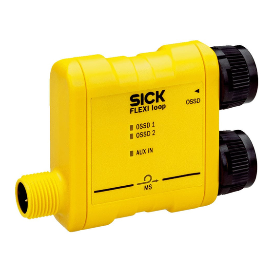
Flexi Loop node. The designation MS (= module status) comes from the Flexi Soft safety controller. O P E R A T I N G I N S T R U C T I O N S | Flexi Loop 8023206/2018-09-11 | SICK... - Page 21 Figure 16: LEDs of the PWRI power supply accessory 8023206/2018-09-11 | SICK O P E R A T I N G I N S T R U C T I O N S | Flexi Loop Subject to change without notice...
- Page 22 PWRI power supply accessory. The Overload LED indicates an output overload. O P E R A T I N G I N S T R U C T I O N S | Flexi Loop 8023206/2018-09-11 | SICK Subject to change without notice...
-
Page 23: Project Planning
(e.g., 8.5 m for 0.34 mm At an ambient temperature of 40 °C. 8023206/2018-09-11 | SICK O P E R A T I N G I N S T R U C T I O N S | Flexi Loop Subject to change without notice... -
Page 24: Other Limits
Make sure the current drawn via VDC and AUX_OUT flows back via the GND pin. O P E R A T I N G I N S T R U C T I O N S | Flexi Loop 8023206/2018-09-11 | SICK... -
Page 25: Division Into Sections
Data flow Power supplies Section 1 max. 4 A 8023206/2018-09-11 | SICK O P E R A T I N G I N S T R U C T I O N S | Flexi Loop Subject to change without notice... -
Page 26: Voltage Drop Via Cables, Flexi Loop Nodes And Flexi Loop Accessories
7 Flexi Loop node. O P E R A T I N G I N S T R U C T I O N S | Flexi Loop 8023206/2018-09-11 | SICK Subject to change without notice... - Page 27 0.5 A and with 1.5 A), the input voltage drops below the permissible value from the 2 Flexi Loop node. 8023206/2018-09-11 | SICK O P E R A T I N G I N S T R U C T I O N S | Flexi Loop Subject to change without notice...
-
Page 28: Possible Solutions
• install the PWRI power supply accessory. O P E R A T I N G I N S T R U C T I O N S | Flexi Loop 8023206/2018-09-11 | SICK Subject to change without notice... -
Page 29: Supply Of Ossd Devices
Reset is realized by pressing and releasing the reset button. This action generates an active high pulse lasting at least 100 ms and maxi‐ mum 30 s. 8023206/2018-09-11 | SICK O P E R A T I N G I N S T R U C T I O N S | Flexi Loop Subject to change without notice... -
Page 30: Implementation Of A Safety Locking Device
The lock must be implemented in the Flexi Soft Designer logic editor (see the “Flexi Loop in the Flexi Soft Designer” operating instructions, part no. 8014522). O P E R A T I N G I N S T R U C T I O N S | Flexi Loop 8023206/2018-09-11 | SICK... - Page 31 Flexi Soft safety controller Signal for interlocking device Actuator status signal 8023206/2018-09-11 | SICK O P E R A T I N G I N S T R U C T I O N S | Flexi Loop Subject to change without notice...
-
Page 32: Mounting
The Flexi Loop nodes can be installed with what is known as a C-Fix bracket. O P E R A T I N G I N S T R U C T I O N S | Flexi Loop 8023206/2018-09-11 | SICK... - Page 33 The C-Fix brackets are suitable for mounting the Flexi Loop nodes on mounting profiles with T-slots. 8023206/2018-09-11 | SICK O P E R A T I N G I N S T R U C T I O N S | Flexi Loop Subject to change without notice...
-
Page 34: Electrical Installation
The safe sensor cascade must be disconnected from the voltage supply before any changes are made. O P E R A T I N G I N S T R U C T I O N S | Flexi Loop 8023206/2018-09-11 | SICK... -
Page 35: Connections
However, the current must be limited to 4 A. Figure 27: Connection example with Flexi Soft 8023206/2018-09-11 | SICK O P E R A T I N G I N S T R U C T I O N S | Flexi Loop Subject to change without notice... -
Page 36: Connections Of The Flexi Loop Nodes
Flexi Soft safety controller (see "Connection to Flexi Soft", page 35). O P E R A T I N G I N S T R U C T I O N S | Flexi Loop 8023206/2018-09-11 | SICK Subject to change without notice... -
Page 37: Connection Of The Flexi Loop Nodes Within A Safe Sensor Cascade
Never disconnect the connection cables of the Flexi Loop nodes. 8023206/2018-09-11 | SICK O P E R A T I N G I N S T R U C T I O N S | Flexi Loop Subject to change without notice... -
Page 38: Connections Of The Emss Flexi Loop Node
The stated colors apply on the usage of pre-assembled cables (should be checked). Figure 31: Connection sketch dual-channel equivalent switch O P E R A T I N G I N S T R U C T I O N S | Flexi Loop 8023206/2018-09-11 | SICK... -
Page 39: Connections Of The Ossd Flexi Loop Node
The stated colors apply on the usage of pre-assembled cables (should be checked). 8023206/2018-09-11 | SICK O P E R A T I N G I N S T R U C T I O N S | Flexi Loop Subject to change without notice... -
Page 40: Connections Of The Pwri Power Supply Accessory
The stated colors apply on the usage of pre-assembled cables (should be checked). O P E R A T I N G I N S T R U C T I O N S | Flexi Loop 8023206/2018-09-11 | SICK... -
Page 41: Commissioning
The effectiveness of the protective device must be checked daily by a specialist or by authorized personnel. 8023206/2018-09-11 | SICK O P E R A T I N G I N S T R U C T I O N S | Flexi Loop Subject to change without notice... -
Page 42: Troubleshooting
No operating voltage, or voltage too low O P E R A T I N G I N S T R U C T I O N S | Flexi Loop 8023206/2018-09-11 | SICK Subject to change without notice... - Page 43 Loop node in the direction of propagation on which the MS LED is no longer flashing green at 1 Hz. 8023206/2018-09-11 | SICK O P E R A T I N G I N S T R U C T I O N S | Flexi Loop Subject to change without notice...
-
Page 44: Leds Of The Emss Flexi Loop Nodes
Non-safe output is active. O Green Non-safe output is inactive. O P E R A T I N G I N S T R U C T I O N S | Flexi Loop 8023206/2018-09-11 | SICK Subject to change without notice... -
Page 45: Leds Of The Ossd Flexi Loop Nodes
Figure 38: LEDs of the PWRI power supply accessory 8023206/2018-09-11 | SICK O P E R A T I N G I N S T R U C T I O N S | Flexi Loop Subject to change without notice... -
Page 46: Extended Diagnostics
You will find detailed information in the “Flexi Loop in the Flexi Soft Designer” operating instructions, part no. 8023208. O P E R A T I N G I N S T R U C T I O N S | Flexi Loop 8023206/2018-09-11 | SICK... -
Page 47: Technical Data
E1 (case b = type 4 testable sensors): 10 ms Minimum cut-off time 8023206/2018-09-11 | SICK O P E R A T I N G I N S T R U C T I O N S | Flexi Loop Subject to change without notice... - Page 48 30 mA (PWR left) / 55 mA (PWR right) SC-FLT-TERM 30 mA O P E R A T I N G I N S T R U C T I O N S | Flexi Loop 8023206/2018-09-11 | SICK Subject to change without notice...
-
Page 49: Emss Flexi Loop Nodes
3.5 … 6.2 mA Input current LOW –2.5 … +2.5 mA 8023206/2018-09-11 | SICK O P E R A T I N G I N S T R U C T I O N S | Flexi Loop Subject to change without notice... -
Page 50: Terminator
Output current monitoring Permissible capacitive load Max. 4.7 mF O P E R A T I N G I N S T R U C T I O N S | Flexi Loop 8023206/2018-09-11 | SICK Subject to change without notice... - Page 51 Current characteristic at 40 °C Tolerance Permissible continuous current Emergency shutdown 8023206/2018-09-11 | SICK O P E R A T I N G I N S T R U C T I O N S | Flexi Loop Subject to change without notice...
-
Page 52: Dimensional Drawings
Dimensional drawing Flexi Loop node Figure 40: Dimensional drawing Flexi Loop node (mm) O P E R A T I N G I N S T R U C T I O N S | Flexi Loop 8023206/2018-09-11 | SICK... -
Page 53: Dimensional Drawing Pwri Power Supply Accessory
Figure 42: Dimensional drawing Flexi Loop termination element (mm) 8023206/2018-09-11 | SICK O P E R A T I N G I N S T R U C T I O N S | Flexi Loop Subject to change without notice... -
Page 54: Accessories
Table 38: Part numbers mounting accessories Part Part number C-Fix bracket 2103178 O P E R A T I N G I N S T R U C T I O N S | Flexi Loop 8023206/2018-09-11 | SICK Subject to change without notice... -
Page 55: Annex
(part number: see the type label entry in the “Ident. no.” field). 8023206/2018-09-11 | SICK O P E R A T I N G I N S T R U C T I O N S | Flexi Loop Subject to change without notice... -
Page 56: Checklist For The Manufacturer
Are you sure that the safety controller was tested fully for safety functionality after each configuration change? O P E R A T I N G I N S T R U C T I O N S | Flexi Loop 8023206/2018-09-11 | SICK... -
Page 57: List Of Figures
42. Dimensional drawing Flexi Loop termination element (mm)........53 8023206/2018-09-11 | SICK O P E R A T I N G I N S T R U C T I O N S | Flexi Loop Subject to change without notice... -
Page 58: List Of Tables
38. Part numbers mounting accessories................ 54 39. Checklist for the manufacturer.................. 56 O P E R A T I N G I N S T R U C T I O N S | Flexi Loop 8023206/2018-09-11 | SICK Subject to change without notice... - Page 59 LIST OF TABLES 8023206/2018-09-11 | SICK O P E R A T I N G I N S T R U C T I O N S | Flexi Loop Subject to change without notice...
- Page 60 Phone +36 1 371 2680 Phone +386 591 788 49 E-Mail office@sick.hu E-Mail office@sick.si India South Africa Phone +91 22 4033 8333 Phone +27 11 472 3733 Further locations at www.sick.com E-Mail info@sick-india.com E-Mail info@sickautomation.co.za SICK AG | Waldkirch | Germany | www.sick.com...
Need help?
Do you have a question about the Flexi Loop and is the answer not in the manual?
Questions and answers