SICK LMS5 Series Operating Instructions Manual
Laser measurement sensors
Hide thumbs
Also See for LMS5 Series:
- Operating instructions manual (94 pages) ,
- Operating instructions manual (112 pages)
Table of Contents
Advertisement
Quick Links
Advertisement
Table of Contents

Related Manuals for SICK LMS5 Series


Summary of Contents for SICK LMS5 Series
- Page 1 O P E R A T I N G I N S T R U C T I O N S LMS5xx LASER MEASUREMENT SENSORS...
- Page 2 This work is protected by copyright. Any rights derived from the copyright shall be reserved for SICK AG. Reproduction of this document or parts of this document is only permissible within the limits of the legal determination of Copyright Law. Any modification, expurgation or translation of this document is prohibited without the express written permission of SICK ©...
-
Page 3: Table Of Contents
Conditions for safe operation of the LMS5xx in an installation ......63 Connections of the LMS5xx ..................67 Preparing the electrical installation ................. 74 Perform electrical installation on the LMS5xx ............76 8013796/ZM63/2017-05-09 © SICK AG · Germany · All rights reserved · Subject to change without notice... - Page 4 11.2 EU declaration of conformity .................. 115 11.3 Glossary ........................115 11.4 Abbreviations ......................116 11.5 List of Figures ......................117 11.6 List of Tables ......................119 8013796/ZM63/2017-05-09 © SICK AG · Germany · All rights reserved · Subject to change without notice...
-
Page 5: About This Document
Standard Resolution (SR) LMS581-10100 PRO Outdoor Standard Resolution (SR) LMS581-20100 PRO Outdoor High Resolution (HR) Tab. 1: Variants of the LMS5xx laser measurement sensor 8013796/ZM63/2017-05-09 © SICK AG · Germany · All rights reserved · Subject to change without notice... -
Page 6: Depth Of Information
You will find further information on the LMS5xx, its accessories as well as documents on the online product page. Please see section 1.5 “Further information” on page 8013796/ZM63/2017-05-09 © SICK AG · Germany · All rights reserved · Subject to change without notice... -
Page 7: Explanation Of Symbols
Instructions to perform actions that contain several steps in sequence are numbered. This symbol refers to additionally available documentation. 8013796/ZM63/2017-05-09 © SICK AG · Germany · All rights reserved · Subject to change without notice... -
Page 8: Further Information
Important Before calling, make a note of all type label data such as type code, serial number, etc. to ensure faster processing. 8013796/ZM63/2017-05-09 © SICK AG · Germany · All rights reserved · Subject to change without notice... -
Page 9: For Your Safety
The use of accessories not specifically approved by SICK is at own risk. IP technology SICK uses standard IP technology in its products. The emphasis is placed on availability of products and services. SICK always assumes the following prerequisites: ... -
Page 10: Modifications And Conversions
In case of any other usage as well as in case of modifications to the LMS5xx, e.g. due to opening the housing and/or breaking the seals during mounting and electrical installation, or to the SICK software, any claims against SICK AG under the warranty will be rendered void. -
Page 11: General Safety Notes And Protective Measures
LMS5xx is fitted. The operator of the system is to be instructed in the use of the device by specialist personnel and must be instructed to read the operating instructions. 8013796/ZM63/2017-05-09 © SICK AG · Germany · All rights reserved · Subject to change without notice... -
Page 12: Hazard Warnings And Operational Safety
LMS5xx. son ensemble. Siehe Fig. 1 on page 13 Fig. 1 on page 13 Voir Fig. 1 on page 13 8013796/ZM63/2017-05-09 © SICK AG · Germany · All rights reserved · Subject to change without notice... - Page 13 If these conditions are not met, e.g. on devices in a widely distributed system over several buildings, potential equalization currents may, due to different ground potentials, flow along the cable shields between the devices and may cause danger. 8013796/ZM63/2017-05-09 © SICK AG · Germany · All rights reserved · Subject to change without notice...
-
Page 14: Quick Stop And Restart
Sensor: Max. 25 W (without load on the outputs) Heating: Additionally max. 65 W Tab. 4: LMS5xx variants: Maximum of power consumption While working, always act in an environmentally responsible manner. 8013796/ZM63/2017-05-09 © SICK AG · Germany · All rights reserved · Subject to change without notice... -
Page 15: Repair
Repairs to the LMS5xx are only allowed to be undertaken by trained and authorized service personnel from SICK AG. Any manipulation or modification of the LMS5xx by the customer will invalidate the manufacturer warranty. 8013796/ZM63/2017-05-09 © SICK AG · Germany · All rights reserved · Subject to change without notice... - Page 16 For your safety Chapter 2 Operating Instructions LMS5xx Laser Measurement Sensors 8013796/ZM63/2017-05-09 © SICK AG · Germany · All rights reserved · Subject to change without notice...
-
Page 17: Product Description
http://www.sick.com/lms5xx Section 11.1 “Ordering information” on page 115 provides an overview of the consumables available for cleaning the front screen. 8013796/ZM63/2017-05-09 © SICK AG · Germany · All rights reserved · Subject to change without notice... -
Page 18: Device Variants
Device variants Object remission Under the following conditions: the SICK cables plugged into the M12 round plug-in connections must be screwed tight. Any electrical connections that are not being used must be fitted with protective caps or plugs that are screwed tight (as in the delivery condition . - Page 19 Heavy Duty Outdoor. Due to the cloning parameter memory that is included, the existing configuration may be transferred to the relevant replacement device automatically on start-up if, for example, a sensor defect occurs. 8013796/ZM63/2017-05-09 © SICK AG · Germany · All rights reserved · Subject to change without notice...
-
Page 20: Type Code
00: Standard 51: Special 90: Bulkscan software Tab. 7: Type code of LMS5xx Not all possible combinations are available according to the type code. 8013796/ZM63/2017-05-09 © SICK AG · Germany · All rights reserved · Subject to change without notice... -
Page 21: Special Features Of The Lms5Xx
2 digital switching inputs, 1 switching output LMS531-10100 4 potential-free relay outputs 4 digital switching inputs Tab. 8: Special features of the LMS5xx variants 8013796/ZM63/2017-05-09 © SICK AG · Germany · All rights reserved · Subject to change without notice... -
Page 22: Differences Between The Lms5Xx Lite, Pro And Heavy Duty Versions
Only possible with Only possible with Only possible with indoor variant indoor variant outdoor variant Tab. 10: Differences between LMS5xx Lite-, PRO and Heavy-Duty 8013796/ZM63/2017-05-09 © SICK AG · Germany · All rights reserved · Subject to change without notice... -
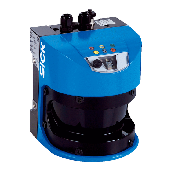
Page 23: Controls And Status Indicators
On the LMS5xx, along with the standard displays described below, the indication functions of the LEDs and the 7segment display can be configured in SOPAS ET. , LMS…, P ROJECT TREE ARAMETER ETWORK NTERFACES ISPLAY 8013796/ZM63/2017-05-09 © SICK AG · Germany · All rights reserved · Subject to change without notice... -
Page 24: Operating Principle Of The Lms5Xx
80 m on light, natural surfaces with an object remission > 100% (e.g. a white house wall). See also section 10.2 “Operating range diagrams” on page 106. 8013796/ZM63/2017-05-09 © SICK AG · Germany · All rights reserved · Subject to change without notice... - Page 25 0.1667°, 0.25°, 0.33°, 0.5°, 0.6667° or 1°. The LMS5xx Lite scans with a scanning frequency of 25, 50 or 75 Hz and angular steps of 0.25°, 0.5° or 1°. 8013796/ZM63/2017-05-09 © SICK AG · Germany · All rights reserved · Subject to change without notice...
- Page 26 (Fig. 9). If the beam is incident at an angle, a corresponding energy and scanning range loss occurs (Fig. Fig. 9: Degree of reflection 8013796/ZM63/2017-05-09 © SICK AG · Germany · All rights reserved · Subject to change without notice...
- Page 27 (see section 3.9.4 “Measured value output for a pulse reflected with multiple echoes” on page 36). 8013796/ZM63/2017-05-09 © SICK AG · Germany · All rights reserved · Subject to change without notice...
- Page 28 (HR) or 0.011 rad (SR) + 13 mm. Expanding laser beam Optical axis Beam diameter at the front screen = 13 mm Fig. 13: Beam expansion 8013796/ZM63/2017-05-09 © SICK AG · Germany · All rights reserved · Subject to change without notice...
- Page 29 Distance intersection point 30 m with the characteristic curve for beam diameter gives a beam size of approx. 150 mm (HR) or 342 mm (SR). 8013796/ZM63/2017-05-09 © SICK AG · Germany · All rights reserved · Subject to change without notice...
- Page 30 LMS5xx stops taking measurements. Depending on the application in which the LMS5xx is used, you can choose between various strategies for the contamination measurement. 8013796/ZM63/2017-05-09 © SICK AG · Germany · All rights reserved · Subject to change without notice...
-
Page 31: Applications
Therefore, there is a wide range of possible applications. Some of these applications are listed below: Container loading/handling/positioning Traffic/transport Robots/pick and place Object/building protection (low false alarm rate) Anti-collision Navigation 8013796/ZM63/2017-05-09 © SICK AG · Germany · All rights reserved · Subject to change without notice... -
Page 32: Measurement Of Objects
It is only possible to output all measured values of a scan in real-time using the Ethernet interface. 8013796/ZM63/2017-05-09 © SICK AG · Germany · All rights reserved · Subject to change without notice... - Page 33 Measured data can be continuously requested using the sEN LMDscandata telegram — measured data are then transferred until the measured value output is stopped using 8013796/ZM63/2017-05-09 © SICK AG · Germany · All rights reserved · Subject to change without notice...
- Page 34 5. Start the output of measured values for a single scan Request <STX>sRN LMDscandata<ETX> LMS5xx answer <STX>sRA LMDscandata<ETX> Depending on the type of error, the sensor may or may not stop measuring. 8013796/ZM63/2017-05-09 © SICK AG · Germany · All rights reserved · Subject to change without notice...
- Page 35 <STX>sRA STlms 7 0 8 00:00:00 8 01.0 1.06 0 0 0<ETX> If the status is other than 7, you must send the request again. 8013796/ZM63/2017-05-09 © SICK AG · Germany · All rights reserved · Subject to change without notice...
- Page 36 LMS5xx will also receive up to 2 or 5 echoes, however it will only display the last echo received and ignore all previous echoes. In the measured value telegram it will output only one value. 8013796/ZM63/2017-05-09 © SICK AG · Germany · All rights reserved · Subject to change without notice...
- Page 37 White (approx. 100 %) Grey (approx. 50 %) Black (approx. 10 %) Reflector (> 80,000 %) Max. signal Distance [m] Fig. 20: Typical RSSI values HR 8013796/ZM63/2017-05-09 © SICK AG · Germany · All rights reserved · Subject to change without notice...
- Page 38 The RSSI values may vary slightly between different devices and over the life time of the sensor. , LMS…, P ROJECT TREE ARAMETER ATA PROCESSING UTPUT DATA CONFIGURATION 8013796/ZM63/2017-05-09 © SICK AG · Germany · All rights reserved · Subject to change without notice...
-
Page 39: Field Application
8013796/ZM63/2017-05-09 © SICK AG · Germany · All rights reserved · Subject to change without notice... - Page 40 An input combination can also be defined for several evaluation cases, e.g. two evaluation cases will then be active simultaneously. Although the LMS5xx Lite has two inputs, only IN1 can be used for the field evaluation. 8013796/ZM63/2017-05-09 © SICK AG · Germany · All rights reserved · Subject to change without notice...
- Page 41 If you use evaluation fields at a distance from the LMS5xx, then the object or the object erroneously measured due to glare is outside the evaluation field and will not be detected. 8013796/ZM63/2017-05-09 © SICK AG · Germany · All rights reserved · Subject to change without notice...
- Page 42 Do not confuse the negation of the result with the setting active high/active low for the outputs (see section 3.10.3 “Operator for the evaluation cases on the output” on page 43). 8013796/ZM63/2017-05-09 © SICK AG · Germany · All rights reserved · Subject to change without notice...
- Page 43 ARAMETER ETWORK NTERFACES IGITAL OUTPUTS The outputs are configured as active high in the pre-setting. You can configure the outputs also as active low. 8013796/ZM63/2017-05-09 © SICK AG · Germany · All rights reserved · Subject to change without notice...
-
Page 44: Inputs And Outputs
High or to Low if an object or a person is detected inside the monitored field. , LMS531, P ROJECT TREE ARAMETER ETWORK NTERFACES ELAY OUTPUTS The following configuration possibilities exist: 8013796/ZM63/2017-05-09 © SICK AG · Germany · All rights reserved · Subject to change without notice... - Page 45 The synchronisation feature can also be used to increase the scanning frequency of an area by placing several units over the same area and adjusting the phases to alternate scanning. 8013796/ZM63/2017-05-09 © SICK AG · Germany · All rights reserved · Subject to change without notice...
- Page 46 1 also acts on the LMS5xx at the top and its output 1. Using the OR operator for the two results, evaluation field infringements on both LMS5xx are signalled on output 1 on the LMS5xx at the top. 8013796/ZM63/2017-05-09 © SICK AG · Germany · All rights reserved · Subject to change without notice...
-
Page 47: Data Interfaces
The factory setting for the host interface is as follows: 57.6 kBd 8 data bits 1 stop bit no parity 8013796/ZM63/2017-05-09 © SICK AG · Germany · All rights reserved · Subject to change without notice... -
Page 48: Data Communication Using Telegrams
The frame for the serial host interface can be configured in SOPAS ET: P , LMS…, ROJECT TREE , area S NTERFACES ERIAL ERIAL HOST INTERFACE 8013796/ZM63/2017-05-09 © SICK AG · Germany · All rights reserved · Subject to change without notice... -
Page 49: Planning
59). To avoid dazzling, do not orient the device toward reflective glass or stainless steel surfaces. These may act as a mirror. 8013796/ZM63/2017-05-09 © SICK AG · Germany · All rights reserved · Subject to change without notice... - Page 50 Recommendation Take into account a safety supplement of approx. 5 mm per meter (0.06 in/ft). 8013796/ZM63/2017-05-09 © SICK AG · Germany · All rights reserved · Subject to change without notice...
-
Page 51: Transport And Storage
Relative humidity: max. 90%, non-condensing. For storage periods of longer than 3 months, check the general condition of all components and packaging on a regular basis. 8013796/ZM63/2017-05-09 © SICK AG · Germany · All rights reserved · Subject to change without notice... - Page 52 Transport and storage Chapter 4 Operating Instructions LMS5xx Laser Measurement Sensors (blank page) 8013796/ZM63/2017-05-09 © SICK AG · Germany · All rights reserved · Subject to change without notice...
-
Page 53: Mounting
– 4 M6 screws for the LMS5xx, screw length dependent on the wall thickness of the mounting bracket used 5.2.3 Necessary tools 4 M6 screws for mounting the SICK fixing bracket on the support, screw length as a function of the wall thickness of the support tool set 8013796/ZM63/2017-05-09... - Page 54 Mounting with mounting kit 3 (part no. 2015625), only in conjunction with mounting kits 1 and 2 Mounting with mounting kit 4 (part no. 2020295) 8013796/ZM63/2017-05-09 © SICK AG · Germany · All rights reserved · Subject to change without notice...
- Page 55 LMS5xx directly on the intended mounting surface. M6×8 Fig. 27: Direct mounting Important During mounting, please observe the dimensional drawings (see section 10.3.1 “Dimensional drawing LMS500” on page 107). 8013796/ZM63/2017-05-09 © SICK AG · Germany · All rights reserved · Subject to change without notice...
- Page 56 2. Mount the LMS5xx on mounting kit 1. Important During mounting, please observe the dimensional drawings (see section 10.3.3 “Dimensional drawings, mounting kits” on page 109). 8013796/ZM63/2017-05-09 © SICK AG · Germany · All rights reserved · Subject to change without notice...
- Page 57 4. Adjust the LMS5xx longitudinally and crosswise. Important During mounting, please observe the dimensional drawings (see section 10.3.3 “Dimensional drawings, mounting kits” on page 109). 8013796/ZM63/2017-05-09 © SICK AG · Germany · All rights reserved · Subject to change without notice...
- Page 58 5. Adjust the LMS5xx longitudinally and crosswise. Important During mounting, please observe the dimensional drawings (see section 10.3.3 “Dimensional drawings, mounting kits” on page 109). 8013796/ZM63/2017-05-09 © SICK AG · Germany · All rights reserved · Subject to change without notice...
- Page 59 Protection hood LMS5xx Fig. 31: Protection hood, upright orientation of the LMS5xx Protection hood LMS5xx Fig. 32: Protection hood, upside down orientation of the LMS5xx 8013796/ZM63/2017-05-09 © SICK AG · Germany · All rights reserved · Subject to change without notice...
- Page 60 Weather protection hood, upright orientation of the LMS5xx For mounting the LMS5xx in combination with the weather protection hood, mounting kit 1 and 2 are required. 8013796/ZM63/2017-05-09 © SICK AG · Germany · All rights reserved · Subject to change without notice...
- Page 61 Placement of two LMS5xx opposed to each other Fig. 35: Crosswise placement of two LMS5xx Fig. 36: Placement of two LMS5xx with parallel offset 8013796/ZM63/2017-05-09 © SICK AG · Germany · All rights reserved · Subject to change without notice...
-
Page 62: Dismanteling The System
3. Undo the mounting screws for the LMS5xx to the mounting bracket and remove the device. Important On final decommissioning, please observe the disposal requirements in section 8.3.1 “Disposal” on page 95 for environmentally correct disposal. 8013796/ZM63/2017-05-09 © SICK AG · Germany · All rights reserved · Subject to change without notice... -
Page 63: Electrical Installation
Correctly grounding the devices/metal surfaces in the system A low-impedance and stable current carrying equipotential bonding between areas with different ground potentials, if necessary 8013796/ZM63/2017-05-09 © SICK AG · Germany · All rights reserved · Subject to change without notice... - Page 64 It is not advisable to open up the cable shields. This would mean that the EMC limit values can no longer be complied with and the safe operation of the device data interfaces can no longer be guaranteed. 8013796/ZM63/2017-05-09 © SICK AG · Germany · All rights reserved · Subject to change without notice...
- Page 65 Grounding point 3 = Metal housing Grounding potential difference = Shielded electrical cable Fig. 42: Insulated assembly of the LMS5xx and the peripheral devices (sample) 8013796/ZM63/2017-05-09 © SICK AG · Germany · All rights reserved · Subject to change without notice...
- Page 66 – og er tilkoplet et kabel-TV nett, kan forårsake brannfare. For å unngå dette skal det ved tilkopling av utstyret til kabel-TV nettet installeres en galvanisk isolator mellom utstyret og kabel-TV nettet. 8013796/ZM63/2017-05-09 © SICK AG · Germany · All rights reserved · Subject to change without notice...
-
Page 67: Connections Of The Lms5Xx
The LMS581 PRO Outdoor has one 5-pole round M12 plug-in connector and two 12- pole round M12 plug-in connectors. The connections are made to the related male connectors or female connectors of the cables. 8013796/ZM63/2017-05-09 © SICK AG · Germany · All rights reserved · Subject to change without notice... - Page 68 Receiver RS-422/RS-232 Receiver RS-422/RS-232 Shield RS Shield RS-422/RS-232 Tab. 22: LMS500 Lite Indoor: Terminal assignment of the “Power/Data/I/O” connection (2 x terminal blocks, 8-pole) 8013796/ZM63/2017-05-09 © SICK AG · Germany · All rights reserved · Subject to change without notice...
- Page 69 OUT6/OUT Sync Switching output 6 / Output Synchronization Tab. 23: LMS500 PRO Indoor: Terminal assignment of the “Power/Data/I/O” connection (2 x terminal blocks, 13-pole) 8013796/ZM63/2017-05-09 © SICK AG · Germany · All rights reserved · Subject to change without notice...
- Page 70 Ground Switching output 1 ... 3/ Synchronization Power supply switching outputs Tab. 27: LMS511 Lite Outdoor: Pin assignment of the “I/O” connection (8-pin M12 female connector, A-coded) 8013796/ZM63/2017-05-09 © SICK AG · Germany · All rights reserved · Subject to change without notice...
- Page 71 Switching output 6 / Output Synchronization Tab. 29: LMS511 PRO, LMS581 PRO and LMS511 Heavy Duty Outdoor: Pin assignment of the “I/O” connection (12-pin M12 female connector, A-coded) 8013796/ZM63/2017-05-09 © SICK AG · Germany · All rights reserved · Subject to change without notice...
- Page 72 Sabotage output GND Sab Ground Sabotage output Tab. 33: LMS531 Lite Security Outdoor: Pin assignment of the “Alarm” connection (8-pin M12 female connector, A-coded) 8013796/ZM63/2017-05-09 © SICK AG · Germany · All rights reserved · Subject to change without notice...
- Page 73 Sabotage output , resistor monitored, contact B Tab. 35: LMS531 PRO Security Outdoor: Pin assignment of the “Alarm” connection (12-pin M12 female connector, A-coded) 8013796/ZM63/2017-05-09 © SICK AG · Germany · All rights reserved · Subject to change without notice...
-
Page 74: Preparing The Electrical Installation
LMS5xx and operation of an LMS5xx with an incorrect configuration. From experience 200 to 300 mm spare cable at the LMS5xx have proven to be adequat. 8013796/ZM63/2017-05-09 © SICK AG · Germany · All rights reserved · Subject to change without notice... - Page 75 To prevent interference, do not lay data cable in parallel with power supply and motor cables over a long run, e.g. in cable ducts. 8013796/ZM63/2017-05-09 © SICK AG · Germany · All rights reserved · Subject to change without notice...
-
Page 76: Perform Electrical Installation On The Lms5Xx
Part no. 6034415, 5 m RJ45 M12×4-pin Part no. 6030928, 10 m 8-pin Part no. 6036158, 20 m LMS5xx Fig. 44: LMS5xx: Ethernet connection using the Ethernet cable 8013796/ZM63/2017-05-09 © SICK AG · Germany · All rights reserved · Subject to change without notice... - Page 77 8. Fit M16 cable entry fitting and tighten. 9. Carefully re-fit the system connector to the LMS500. 10. Tighten the fixing screws for the system connector. 8013796/ZM63/2017-05-09 © SICK AG · Germany · All rights reserved · Subject to change without notice...
- Page 78 Part no. 6036159, 5 m: 19.2 V Part no. 6042565, 10 m: 19.7 V Part no. 6042564, 20 m: 21.4 V 8013796/ZM63/2017-05-09 © SICK AG · Germany · All rights reserved · Subject to change without notice...
- Page 79 LMS511PRO/Heavy Duty LMS581 PRO Grey+pink = CAN bus low Red+blue = CAN bus high Fig. 48: LMS511 PRO/LMS581 PRO Security/LMS511 Heavy Duty: “Data” connection 8013796/ZM63/2017-05-09 © SICK AG · Germany · All rights reserved · Subject to change without notice...
- Page 80 Part no. 6036157, 20 m Grey = Error A Pink = Error B Brown = Alarm B LMS531 Lite Security Fig. 51: LMS531 Lite Security: “Alarm” connection 8013796/ZM63/2017-05-09 © SICK AG · Germany · All rights reserved · Subject to change without notice...
- Page 81 LMS531 PRO Violet = Disq. B Security Grey +pink = Sab R A Red+blue = Sab R B Fig. 53: LMS531 PRO Security: “Alarm” connection“ 8013796/ZM63/2017-05-09 © SICK AG · Germany · All rights reserved · Subject to change without notice...
- Page 82 11 V. Wiring encoder inputs (LMS5xx PRO/Heavy Duty only) encoder INC1 IN3 0° INC2 IN4 90° LMS5xx Fig. 56: Wiring encoder inputs 8013796/ZM63/2017-05-09 © SICK AG · Germany · All rights reserved · Subject to change without notice...
- Page 83 OUT3 ... 6 OUT3 ... 6 = 100 mA GND V LMS5xx Fig. 59: Connection of the outputs 3 ... 6 to a PLC (active high) 8013796/ZM63/2017-05-09 © SICK AG · Germany · All rights reserved · Subject to change without notice...
- Page 84 6.4.4 “General conditions for the data interfaces” on page LMS5xx Host RS-232 TD– RD– Host LMS5xx TD– RD– RS-422 Fig. 61: Wiring of the RS232 or RS422 interface 8013796/ZM63/2017-05-09 © SICK AG · Germany · All rights reserved · Subject to change without notice...
-
Page 85: Commissioning And Configuration
The configuration software SOPAS ET, the current system prerequisites for the PC, and the instructions for downloading the software and the device description file(s) can be found online at: http://www.sick.com/SOPAS_ET 8013796/ZM63/2017-05-09 © SICK AG · Germany · All rights reserved · Subject to change without notice... -
Page 86: Establish Communication With The Lms5Xx
USB (see Fig. 43 on page 76) or Ethernet (see Fig. 44 on page 76) or RS-232/RS-422 (see Fig. 46 on page 8013796/ZM63/2017-05-09 © SICK AG · Germany · All rights reserved · Subject to change without notice... - Page 87 A scan is performed for devices connected via the connection. SOPAS ET adds the devices found to the project tree and uploads the actual parameter set from the device. 8013796/ZM63/2017-05-09 © SICK AG · Germany · All rights reserved · Subject to change without notice...
-
Page 88: Initial Commissioning
P window (right mouse ARAMETER INFO button when the pointer is positioned over the parameter). 8013796/ZM63/2017-05-09 © SICK AG · Germany · All rights reserved · Subject to change without notice... - Page 89 SOPAS ET. Resetting the configuration Recommendation To reset the LMS5xx to the default delivery status, please use the “Factory Default” option in the SOPAS software. 8013796/ZM63/2017-05-09 © SICK AG · Germany · All rights reserved · Subject to change without notice...
-
Page 90: Connection And Test Measurement
4. After completing the test measurement successfully, save the configuration permanently to the LMS5xx: menu LMS…, P ARAMETER AVE PERMANENT 8013796/ZM63/2017-05-09 © SICK AG · Germany · All rights reserved · Subject to change without notice... -
Page 91: Maintenance
LMS531 Lite/PRO, LMS581 PRO: two stickers, LMS511 Heavy Duty: three stickers). Claims under the warranty against SICK AG will be rendered void if the screwed housing is opened and/or the seals are damaged. The housing is only allowed to be opened by SICK authorized service personnel. - Page 92 Make sure that the inlay sealing, the supporting surface opposite, and all the electrical contacts of the system connector are free from dirt and moisture. 8013796/ZM63/2017-05-09 © SICK AG · Germany · All rights reserved · Subject to change without notice...
- Page 93 8. Configure the replacement device manually by using the parameter set of the former device saved on the PC due to the saving concept (see chapter 7 “Commissioning and configuration” on page 85). 8013796/ZM63/2017-05-09 © SICK AG · Germany · All rights reserved · Subject to change without notice...
- Page 94 However, a test based on the regulations for daily testing, or a functional test, must be carried out. 8013796/ZM63/2017-05-09 © SICK AG · Germany · All rights reserved · Subject to change without notice...
-
Page 95: Decommissioning
Following correct disassembly, pass on any commercially viable disassembled components for recycling. Separate materials as far as possible by type. SICK AG is not currently able to take back devices that can no longer be used. 8013796/ZM63/2017-05-09 © SICK AG · Germany · All rights reserved · Subject to change without notice... - Page 96 Maintenance Chapter 8 Operating Instructions LMS5xx Laser Measurement Sensors (blank page) 8013796/ZM63/2017-05-09 © SICK AG · Germany · All rights reserved · Subject to change without notice...
-
Page 97: Troubleshooting
Ð diagnostics with the aid of SOPAS ET. Switch the device off and back on again. Tab. 41: Error displays of the LEDs 8013796/ZM63/2017-05-09 © SICK AG · Germany · All rights reserved · Subject to change without notice... -
Page 98: Indications Of The 7-Segment Display
LMS5xx. It is used for diagnostics over extended periods and for the analysis of malfunctions or for the optimisation of processes. , LMS…, M ROJECT TREE ONITOR IELD EVALUATION LOGGING 8013796/ZM63/2017-05-09 © SICK AG · Germany · All rights reserved · Subject to change without notice... -
Page 99: Sick Support
Important Before calling, make a note of all type label data such as type code, serial number, etc. to ensure faster processing. 8013796/ZM63/2017-05-09 © SICK AG · Germany · All rights reserved · Subject to change without notice... - Page 100 Troubleshooting Chapter 9 Operating Instructions LMS5xx Laser Measurement Sensors (blank page) 8013796/ZM63/2017-05-09 © SICK AG · Germany · All rights reserved · Subject to change without notice...
-
Page 101: Technical Specifications
PRO/Heavy Duty, LMS581-20100 PRO LMS511-1x100 Lite/PRO/Heavy Duty, LMS531- 40 m 11100 Lite/PRO, LMS581-10100 PRO Power-up delay 30 s 60 s Tab. 43: Data sheet LMS5xx 8013796/ZM63/2017-05-09 © SICK AG · Germany · All rights reserved · Subject to change without notice... - Page 102 Excellent weather resistance as per EN 1706:2010-03, table B.1 Front screen Material Polycarbonate Surface finish Outside with scratch-resistant coating Tab. 43: Data sheet LMS5xx (cont.) 8013796/ZM63/2017-05-09 © SICK AG · Germany · All rights reserved · Subject to change without notice...
- Page 103 With 0.5 mm² wire cross-section 110 m (approx. 22 AWG) With 0.25 mm² wire cross-section 50 m (approx. 24 AWG) Tab. 43: Data sheet LMS5xx (cont.) 8013796/ZM63/2017-05-09 © SICK AG · Germany · All rights reserved · Subject to change without notice...
- Page 104 Velocity range that can be sampled Forward From +100 mm/s to +20,000 mm/s Backward From –10 mm/s to –20,000 mm/s Tab. 43: Data sheet LMS5xx (cont.) 8013796/ZM63/2017-05-09 © SICK AG · Germany · All rights reserved · Subject to change without notice...
- Page 105 Without fixing screws and projection of cable glands with system connector mounted. 6 A for t < 50 s. 7) Outputs are short-circuit protected (no overload protection). 8013796/ZM63/2017-05-09 © SICK AG · Germany · All rights reserved · Subject to change without notice...
-
Page 106: Operating Range Diagrams
Scanning range max. 80 m (262.47 ft) Scanning range for objects up to 10 % remission 40 m (131.23 ft) Fig. 65: Operating range LMS5xx Standard Resolution 8013796/ZM63/2017-05-09 © SICK AG · Germany · All rights reserved · Subject to change without notice... -
Page 107: Dimensional Drawings
Chapter 10 LMS5xx 10.3 Dimensional drawings 10.3.1 Dimensional drawing LMS500 Connector range ca. 80 mm All dimensions in mm Fig. 66: Dimensional drawing LMS500 8013796/ZM63/2017-05-09 © SICK AG · Germany · All rights reserved · Subject to change without notice... - Page 108 Operating Instructions LMS5xx Laser Measurement Sensors 10.3.2 Dimensional drawing LMS511/LMS531/LMS581 Connector range environment 80 mm All dimensions in mm Fig. 67: Dimensional drawing LMS511/LMS531/LMS581 8013796/ZM63/2017-05-09 © SICK AG · Germany · All rights reserved · Subject to change without notice...
- Page 109 Operating Instructions Chapter 10 LMS5xx 10.3.3 Dimensional drawings, mounting kits Sensor Mounting kit 1 All dimensions in mm Fig. 68: Dimensional drawing, mounting kit 1 8013796/ZM63/2017-05-09 © SICK AG · Germany · All rights reserved · Subject to change without notice...
- Page 110 Operating Instructions LMS5xx Laser Measurement Sensors Sensor Mounting kit 1 Mounting kit 2 All dimensions in mm Fig. 69: Dimensional drawing, mounting kit 2 8013796/ZM63/2017-05-09 © SICK AG · Germany · All rights reserved · Subject to change without notice...
- Page 111 Chapter 10 LMS5xx Sensor Mounting kit 1 Mounting kit 2 Mounting kit 3 All dimensions in mm Fig. 70: Dimensional drawing, mounting kit 3 (mm) 8013796/ZM63/2017-05-09 © SICK AG · Germany · All rights reserved · Subject to change without notice...
- Page 112 Chapter 10 Operating Instructions LMS5xx Laser Measurement Sensors 10.3.4 Dimensional drawings, weather protection hoods All dimensions in mm Fig. 71: Dimensional drawing protection hood 8013796/ZM63/2017-05-09 © SICK AG · Germany · All rights reserved · Subject to change without notice...
- Page 113 Technical specifications Operating Instructions Chapter 10 LMS5xx (63) 39.4 60,5 All dimensions in mm Fig. 72: Dimensional drawing weather protection hood 8013796/ZM63/2017-05-09 © SICK AG · Germany · All rights reserved · Subject to change without notice...
- Page 114 Technical specifications Chapter 10 Operating Instructions LMS5xx Laser Measurement Sensors (blank page) 8013796/ZM63/2017-05-09 © SICK AG · Germany · All rights reserved · Subject to change without notice...
-
Page 115: Annex
SOPAS ET Configuration software, used for the offline configuration (adaptation to the read situation on-site) and the online operation of the LMS5xx in dialog mode. 8013796/ZM63/2017-05-09 © SICK AG · Germany · All rights reserved · Subject to change without notice... -
Page 116: Abbreviations
SOPAS device driver = device description file for SOPAS ET SOPAS ET SICK OPEN PORTAL for APPLICATION and SYSTEMS Engineering Tool = configuration software for the configuration of the LMS5xx 8013796/ZM63/2017-05-09 © SICK AG · Germany · All rights reserved · Subject to change without notice... -
Page 117: List Of Figures
Fig. 37: Currents in the cable shields due to differences in ground potential ....55 Fig. 38: Use of electro-optical signal converters ............... 56 8013796/ZM63/2017-05-09 © SICK AG · Germany · All rights reserved · Subject to change without notice... - Page 118 Dimensional drawing, mounting kit 2 ..............90 Fig. 62: Dimensional drawing, mounting kit 3 ..............91 Fig. 63: Dimensional drawing weather protection hoods ..........92 Fig. 64: EC declaration of conformity .................95 8013796/ZM63/2017-05-09 © SICK AG · Germany · All rights reserved · Subject to change without notice...
-
Page 119: List Of Tables
Tab. 29: LMS511 PRO, LMS581 PRO and LMS511 Heavy Duty Outdoor: Pin assignment of the “I/O” connection (12-pin M12 female connector, A-coded) ......................... 71 8013796/ZM63/2017-05-09 © SICK AG · Germany · All rights reserved · Subject to change without notice... - Page 120 Tab. 41: Error displays of the LEDs ..................97 Tab. 42: Indications of the 7segment display ..............98 Tab. 43: Data sheet LMS5xx ..................... 101 Tab. 44: Consumables ....................... 115 8013796/ZM63/2017-05-09 © SICK AG · Germany · All rights reserved · Subject to change without notice...
- Page 121 Annex Operating Instructions Chapter 11 LMS5xx (blank page) 8013796/ZM63/2017-05-09 © SICK AG · Germany · All rights reserved · Subject to change without notice...
- Page 122 Phone +36 1 371 2680 Phone +386 591 788 49 E-Mail office@sick.hu E-Mail office@sick.si India South Africa Phone +91 22 6119 8900 Phone +27 11 472 3733 Further locations at www.sick.com E-Mail info@sick-india.com E-Mail info@sickautomation.co.za SICK AG | Waldkirch | Germany | www.sick.com...
Need help?
Do you have a question about the LMS5 Series and is the answer not in the manual?
Questions and answers