Sign In
Upload
Manuals
Brands
SICK Manuals
Accessories
Flexi Loop
User Manuals: SICK Flexi Loop Safety Switch
Manuals and User Guides for SICK Flexi Loop Safety Switch. We have
2
SICK Flexi Loop Safety Switch manuals available for free PDF download: Operating Instructions Manual
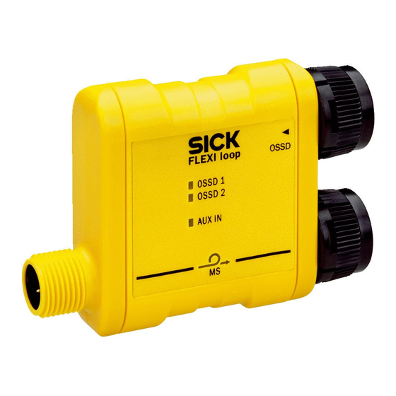
SICK Flexi Loop Operating Instructions Manual (104 pages)
Safe sensor cascade hardware
Brand:
SICK
| Category:
Accessories
| Size: 7 MB
Table of Contents
Table of Contents
3
1 About this Document
6
Function of this Document
6
Scope
6
Target Groups and Structure of These Operating Instructions
6
Additional Information
7
Symbols and Document Conventions
7
2 Safety Information
9
General Safety Notes
9
Correct Use
9
Requirements for the Qualification of Personnel
9
3 Product Description
11
Structure and Function
11
System Requirements
12
Safety by Means of Flexi Loop
12
Subdivision of the Safe Sensor Cascade
13
Supply of Power
14
Principle of Operation
15
Operating Principle of Flexi Soft
15
Operating Principle on Flexi Classic
17
Protection against Tampering
20
Device Components
20
Flexi Loop Node
20
Flexi Loop Terminator
22
Flexi Loop Accessories
22
Status Indicators
24
4 Design
27
Total Current
27
Permissible Total Current of a Section
27
Permissible Inrush Current
27
Other Limits
27
Connection Facilities
28
Division into Sections
30
Voltage Drop Via Cables, Flexi Loop Nodes and Flexi Loop Accessories
31
Examples for the Voltage Drop
31
Possible Solutions
34
Supply of OSSD Devices
34
Integration in the Electrical Control
34
Implementation of Reset
34
Implementation of a Safety Locking Device
36
5 Installation and Mounting
40
Scope of Delivery
40
Mounting in a Cable Channel
40
Mounting with Cable Tie
40
Mounting with C-Fix Bracket
40
6 Electrical Installation
42
Safety
42
Connections
42
Connection to Flexi Soft
42
Connection to Flexi Classic
43
Connections of the Flexi Loop Nodes
44
Connection of the Flexi Loop Nodes
45
Connections of the EMSS Flexi Loop Node
46
Connections of the OSSD Flexi Loop Node
47
Connections of the PWRI Power Supply Accessory
48
Connections of the MSTR1 Flexi Loop Accessory
48
Connections of the MSTR2 Flexi Loop Accessory
49
Connections of the DIAG Flexi Loop Accessory
50
Connection of Flexi Loop YCON1 and YCON2 Adapters
50
Connections of the Flexi Loop YCON1 Adapter
51
Connections of the Flexi Loop YCON2 Adapter
52
7 Configuration
55
Prerequisites
55
Safety
55
Configuration of Protection against Tampering with the MSTR Flexi Loop Accessory
55
Configuration with a Standard Controller
57
Prerequisites
57
Configuration of the Hardware
57
Options for Application Design in the PLC
61
8 Commissioning
67
Display Sequence During Switching on
67
Commissioning Using the DIAG Flexi Loop Accessory or the MSTR Flexi Loop Accessory
67
Test Notes
67
Thorough Checks before the Initial Commissioning
68
Regular Thorough Check of the Protective Device by Qualified Safety Personnel
68
Daily Functional Checks of the Protective Device
68
9 Troubleshooting
69
In the Event of Faults or Errors
69
SICK Support
69
Indications of the Leds
69
Ms Led
69
Leds of the EMSS Flexi Loop Nodes
71
Leds of the OSSD Flexi Loop Nodes
72
Leds of the PWRI Power Supply Accessory
72
Leds of the MSTR1 Flexi Loop Accessory
73
Leds of the MSTR2 Flexi Loop Accessory
74
Leds of the DIAG Flexi Loop Accessory
76
Extended Diagnostics
77
Diagnostics Using the MSTR2 Flexi Loop Accessory
77
Test Tools for the Configuration
79
10 Technical Data
81
Data Sheet
81
Overall System
81
All Flexi Loop Nodes and Flexi Loop Accessories
81
EMSS Flexi Loop Node (FLN-EMSS0000105 and FLN-EMSS1100108)
83
OSSD Flexi Loop Node (FLN-OSSD1000105 and FLN-OSSD1100108)
84
Terminator
84
PWRI Power Supply Accessory
85
MSTR Flexi Loop Accessory
86
Dimensional Drawings
87
Dimensional Drawing Flexi Loop Node
87
Dimensional Drawing PWRI Power Supply Accessory
88
Dimensional Drawing Terminator
88
Dimensional Drawing C-Fix Bracket
89
Dimensional Drawing MSTR Flexi Loop Accessory
90
Dimensional Drawing DIAG Flexi Loop Accessory
91
Dimensional Drawing for Flexi Loop YCON Adapter
91
Compatibility
92
11 Ordering Information
93
Flexi Loop Node
93
Flexi Loop Accessories
93
12 Accessories
95
Plug Connectors
95
Pre-Assembled Cables
95
Mounting Accessories
96
13 Annex
97
Compliance with EU Directives
97
Checklist for the Manufacturer
98
14 List of Figures
99
15 List of Tables
101
Advertisement
SICK Flexi Loop Operating Instructions Manual (60 pages)
Safe sensor cascade hardware
Brand:
SICK
| Category:
Accessories
| Size: 5 MB
Table of Contents
Table of Contents
3
Ordering Information
6
Scope of Delivery
6
Flexi Loop Node
6
Flexi Loop Accessories
6
About this Document
7
Function of this Document
7
Scope
7
Target Groups and Structure of These Operating Instructions
7
Additional Information
8
Symbols and Document Conventions
8
Safety Information
10
General Safety Notes
10
Correct Use
10
Requirements for the Qualification of Personnel
10
Product Description
12
Structure and Function
12
System Requirements
13
Safety by Means of Flexi Loop
13
Subdivision of the Safe Sensor Cascade
14
Supply of Power
15
Principle of Operation
16
Operating Principle of Flexi Soft
16
Protection against Tampering
18
Device Components
18
Flexi Loop Node
18
Flexi Loop Terminator
19
Flexi Loop Accessories
20
Status Indicators
20
Project Planning
23
Total Current and Power Failure
23
Total Current
23
Permissible Total Current of a Section
23
Permissible Inrush Current
23
Other Limits
24
Connection Facilities
24
Division into Sections
25
Voltage Drop Via Cables, Flexi Loop Nodes and Flexi Loop Accessories
26
Examples for the Voltage Drop
26
Possible Solutions
28
Supply of OSSD Devices
29
Integration in the Electrical Control
29
Implementation of Reset
29
Implementation of a Safety Locking Device
30
Mounting
32
Mounting in a Cable Channel
32
Mounting with Cable Tie
32
Mounting with C-Fix Bracket
32
Electrical Installation
34
Safety
34
Connections
35
Connection to Flexi Soft
35
Connections of the Flexi Loop Nodes
36
Connection of the Flexi Loop Nodes Within a Safe Sensor Cascade
37
Connections of the EMSS Flexi Loop Node
38
Connections of the OSSD Flexi Loop Node
39
Connections of the PWRI Power Supply Accessory
40
Commissioning
41
Safety
41
Display Sequence During Switching on
41
Test Notes
41
Thorough Checks before the Initial Commissioning
41
Regular Thorough Check of the Protective Device by Qualified Safety Personnel
41
Daily Functional Checks of the Protective Device
41
Troubleshooting
42
In the Event of Faults or Errors
42
SICK Support
42
Indications of the Leds
42
Ms Led
42
Leds of the EMSS Flexi Loop Nodes
44
Leds of the OSSD Flexi Loop Nodes
45
Leds of the PWRI Power Supply Accessory
45
Extended Diagnostics
46
Technical Data
47
Data Sheet
47
Overall System
47
All Flexi Loop Nodes and Flexi Loop Accessories
47
EMSS Flexi Loop Nodes
49
Emss8)
49
OSSD Flexi Loop Nodes
49
Ossd8)
49
Terminator
50
PWRI Power Supply Accessory
50
Dimensional Drawings
52
Dimensional Drawing Flexi Loop Node
52
Dimensional Drawing PWRI Power Supply Accessory
53
Dimensional Drawing Terminator
53
Accessories
54
Mounting Accessories
54
Annex
55
Compliance with EU Directives
55
Checklist for the Manufacturer
56
List of Figures
57
List of Tables
58
Advertisement
Related Products
SICK F6 Series
SICK Flexi Classic
SICK Flexi Classic series
SICK FlexChain
SICK Flexi Soft
SICK Flexi Compact
SICK flexLock
SICK FLOWSIC550
SICK FLOWSIC100-XT-H
SICK FLPS Series
SICK Categories
Accessories
Security Sensors
Measuring Instruments
Scanner
Barcode Reader
More SICK Manuals
Login
Sign In
OR
Sign in with Facebook
Sign in with Google
Upload manual
Upload from disk
Upload from URL