Advertisement
Quick Links
Advertisement

Related Manuals for FUFU & GAGA Shoe Storage Cabinet


Summary of Contents for FUFU & GAGA Shoe Storage Cabinet
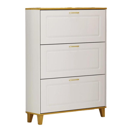
- Page 1 Shoe Storage Cabinet Version:09/20/2022 1/17...
- Page 2 IMPORTANT INFORMATION! please read the entire manual before starting to assemble and/or using this product.follow the manual thoroughly and keep it for further reference. AVOID SCRATCHES! In order to avoid scratching this furnuture should be assembled on a soft layer-could be a rug. IMPROVE EFFICIENCY ! Try to find a partner to install with you, which can speed up...
- Page 3 Please prepare the following tools When installing, please carefully confirm whether each screw corresponds to the manual, accessories with similar shapes can be distinguished by size A x 8 B x 8 C x 12 D x 2 E x 6 4 x 40 mm 4 x 16 mm 6 x 35 mm...
- Page 4 10 x3 4/17...
- Page 5 A x 4 O x 6 P x 6 6 x 35 mm Knock part(O,P) into corresponding holes in No.3 and No.4 plate as shown. Insert quickfit screw(A) into No.3 and No.4 plate with a screwdriver as shown. 5/17...
- Page 6 K x 2 R x 2 B x 4 C x 4 6 x 35 mm 15 x 10 mm 6 x 30 mm 4 x 12 mm Insert quickfit screw(A) into No.1 plate with a screwdriver as shown. Fix part(R) to No.1 plate with screw(K) as shown.
- Page 7 S x 4 6 x 30 mm 4 x 35 mm Slide another No.5 plate into available slots in No.3, No.4 and No.7 plates at first. Cover No.2 plate using wooden dowel(C), then fix with screw(S) as shown. 如图所示 ;2,3,4,板插入C木榫,与 1号 7/17...
- Page 8 G x 4 6 x 30 mm Fix No.8 leg to No.2 plate using screw(G) as shown. 板 8/17...
- Page 9 B x 4 C x 4 15 x 10 mm 6 x 30 mm Slide another No.6 plate into available slots in No.3, No.4 and No.7 plates at first. Cover No.1 plate to the top using wooden dowel(C), then turn cam lock(B) clockwise to tighten as shown.
- Page 10 T x 12 x 12 3 x 16 mm Reinforce back plate using part(I) and screw(T) as shown. 10/17...
- Page 11 Q x 2 Drill holes on your wall, and knock part(Q) into. 4x40 mm Install anit-tipping device with screw(D) as shown. 11/17...
- Page 12 H x 3 E x 6 J x 18 4 x 16 mm 4 x 12 mm L x 3 Fix plastic part(L,M) to No.9 plate with screw(J) as shown, Fix handle(H) with screw(E). 12/17...
- Page 13 J x 12 4 x 12 mm Attach No.11 and No.10 plate to the plastic parts and fix with screw(J) as shown. 13/17...
- Page 14 N x 6 J x 6 4x12 mm Fix these drawers to side plates of the unit by fixing plastic part using part(N) and screw(J) as shown. 14/17...
- Page 15 J x 6 4x12 mm Fix sides of No.10 plate to plastic part with screw(J) as shown. 15/17...
Need help?
Do you have a question about the Shoe Storage Cabinet and is the answer not in the manual?
Questions and answers