Table of Contents
Advertisement
Advertisement
Table of Contents
Troubleshooting

Related Manuals for Furuno FE-800


Summary of Contents for Furuno FE-800
- Page 1 OPERATOR'S MANUAL NAVIGATIONAL ECHO SOUNDER FE-800 Model www.furuno.com...
- Page 3 How to discard a used battery Some FURUNO products have a battery(ies). To see if your product has a battery, see the chapter on Maintenance. If a battery is used, tape the + and - terminals of battery before disposal to prevent fire, heat generation caused by short circuit.
- Page 4 Electrical shock can result. at the switchboard and contact a FURUNO service technician. Use the proper fuse. Use of the wrong fuse can cause fire or electrical shock.
- Page 5 No user-serviceable Warning label(s) is(are) attached to the parts inside. equipment. Do not remove the label(s). If a label is missing or damaged, contact a FURUNO agent or dealer about replacement. Name: Warning Label 1 Type: 86-003-1011-3 Code No.: 100-236-233...
-
Page 6: Table Of Contents
2.9.2 Internal time.......33 1.7 Gain...........10 2.10 Key Beeps.........33 1.7.1 How to adjust the gain ..10 2.11 How to Set Up the FE-800 for 1.7.2 Automatic Operation ..11 Data Recording ......34 1.7.3 How to offset the auto gain ..11 2.12 How to Set Draught from External 1.8 Clutter........12... -
Page 7: Foreword
ISO 9001 standards as certified by the Lloyd’s Register of Quality Assurance System. Features The FE-800 is a colour navigation echo sounder which operates with 50 or 200 kHz frequency. The FE-800 is comprised of a control unit, transceiver, matching box and transducer. Echoes are output on an 8.4-inch LCD screen. - Page 8 1251003-01.xx “xx” indicates minor version numbers. CE/UKCA declaration With regards to CE/UKCA declarations, please refer to our website (www.furuno.com) for further information about RoHS conformity declarations. Disclosure of Information about China RoHS With regards to China RoHS information for our products, please refer to our website...
-
Page 9: System Configuration
SYSTEM CONFIGURATION DISPLAY UNIT PRINTER PP-505-FE FE-8010 TRANSCEIVER UNIT FE-8020 (No.2) REMOTE DISPLY TRANSCEIVER UNIT RD-20 or RD-50 FE-8020 IEC-61162-1 x 2 IEC-61162-1 x 4 IEC-61162-450 POWER-FAIL KP Output 100-230 VAC JUNCTION BOX JISF8821-1MO MATCHING BOX MATCHING BOX MB-504 MB-502 TRANSDUCER TRANSDUCER 200B-8B... -
Page 10: Operation
OPERATION Controls All operations of the FE-800 are carried out with the controls on the front panel of the display unit. Some functions require a long key press, while others require a short key press. Removing the cover While pressing the center with your thumbs as illustrated, pull the cover towards you to remove it. -
Page 11: How To Turn The Power On/Off
Press any Key to continue. Self-test results After the self-test completes, the mode used before the FE-800 was turned off is activated. You can now change modes freely (See section 1.4.) Note: If any errors occur during the self-test process, the self-test stops the startup procedure. -
Page 12: Panel And Key Brilliance
Refer to the section 2.13. 1.3.1 Day/Night Mode (Dimmer Mode: FE-800) The FE-800 has Day and Night display settings to allow better screen visibility. To switch between modes, do the following: 1. Press the MENU/ESC key to open the Main menu. -
Page 13: Day/Dusk/Night Mode (Dimmer Mode: Ecdis)
1. OPERATION 1.3.2 Day/Dusk/Night Mode (Dimmer Mode: ECDIS) In ECDIS dimmer mode, Day, Dusk and Night settings are available, to allow better screen visibil- ity. To switch between modes, do the following: 1. Press the MENU/ESC key to open the Main menu. 2. -
Page 14: Display Modes And Screen Indications
1. OPERATION Display Modes and Screen Indications The FE-800 has 3 main display modes: NAV, HISTORY, OS DATA. The display modes are set in a cycle pattern, and each press of the DISP key changes the selected mode, in the sequence shown below. -
Page 15: Nav Mode
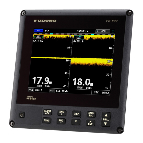
Indicates time and time setting (UTC, Local, Time). 1.4.1 NAV Mode This is the default mode for the FE-800. The screen shows depth and echo from FORE and AFT positions. The default display order of the echo readings is AFT - FORE. -
Page 16: History Mode
Time (location) in sounding depth history. Move this indicator using or . FORE/AFT history readings are displayed at the bottom of this screen. Change indicator. This line appears in the case of any de-synchronization between the FE-800 and connected sensors or units. -
Page 17: Os Data Mode
This mode shows Own Ship Data (OS DATA), and is only available if the [Time Adjust] setting in the [Service Menu] is set to [External]. To change the [Time Adjust] settings in the [Service Menu], consult a FURUNO technician. The OS DATA mode requires a connected EPFS device, such as GPS. If there is no device con- nected, or connection is interrupted, the OS DATA is displayed as shown in the above left figure. -
Page 18: Menu Overview
• [System] menu [Parameters] [FE-8020 No.2] • [System] menu [Information] [FE-8020 No.2] To enable [FE-8020 No.2], consult a FURUNO technician. Note 2: For brevity, all further references to the ENT key are written as “ENT key”. -
Page 19: How To Select A Range
1. OPERATION How to Select a Range The range can be set either manually or automatically. In the auto mode, the range will self-adjust to provide as clear as possible an image. The auto mode is cancelled when the range is manually adjusted. -
Page 20: Automatic Operation
1. OPERATION 1.7.2 Automatic Operation The gain and clutter (low level noise) adjustments can be done automatically. How to turn automatic operation on or off 1. Press the MENU/ESC key to open the Main menu. 2. Select [Sounder] using or , then press the ENT key. 3. -
Page 21: Clutter
1. OPERATION Clutter Low level noise can cause your display to look “cluttered” with unnecessary dots. These are caused mainly by dirty water or noise. This kind of noise can be suppressed by adjusting the clutter. Note: To manually adjust the clutter, you must first turn [AUTO GAIN] off. 1. -
Page 22: Pict Advance
1. OPERATION 1.10 PICT Advance The picture advance menu allows you determine the speed at which the vertical scan lines run across the screen. 1. Press the MENU/ESC key to open the Main menu. 2. Select [Sounder] using or , then press the ENT key. 3. -
Page 23: How To Use The Function Key
1.13 How to Output to External Equipment The FE-800 can output depth information from one transceiver to external equipment, such as ECDIS. To select the transceiver which will output to the external equipment, do the following: 1. Press the MENU/ESC key to open the Main menu. -
Page 24: How To Choose A Transceiver
1.14 How to Choose a Transceiver If your FE-800 is connected to two transceivers, you can switch between the transceivers using the procedure below. Note: If [FE-8020 No.2] is not enabled in the [Service Menu], this menu is not selectable. -
Page 25: How To Set Draught
1. OPERATION 3. Select [DEPTH(BELOW)] using or , then press the ENT key. This will open a pop-up. 4. Select the location to take the depth reading from, then press ENT to apply the settings and close the pop-up window. The available options are [Transducer], [Surface] and [Keel]. 5. -
Page 26: Logbook
1. OPERATION 1.17 Logbook The FE-800 stores log data at five second intervals, with a maximum log period of 24 hours. Once the maximum number of entries is reached, the oldest entry is deleted to make room for the youngest entry. -
Page 27: How To Change The Unit Of Measurement
1. OPERATION Number Description Currently displayed time setting. [UTC]: Coordinated Universal Time. [Local]: Time with UTC difference calculated. [Time]: Unit’s internal clock time. When the external time source is unavailable, a “*” appears to the left of the time. If [Time Adjust ] is set to Internal, the color changes according to the setting se- lected at section 1.20. -
Page 28: How To Change The Colour Scheme
1. OPERATION 1.20 How to Change the Colour Scheme You can change the colour scheme of the display as follows: 1. Press the MENU/ESC key to open the Main menu. 2. Select [Display] using or , then press the ENT key. 3. -
Page 29: How To Adjust The Dimmer Presets
1. OPERATION Note 2: When the transducer selected for echo display output and depth display differ, a pop-up message similar to the one shown to the right is displayed. To use the same transducer for information displayed, match the settings for [Output Depth] on the Main menu with the setting selected at section 1.21.1. -
Page 30: System Menu
SYSTEM MENU The [System Menu] should be preset at installation. Normally, there is no need to access this menu. Note: The echo display will be cleared when the [System Menu] is opened. How to Set the Basic Range Scale Use the table below for reference when changing the range scale settings. Depending on your configuration, some options may not be available. -
Page 31: How To Set Transducer Parameters
If the level is set too low, the FE-800 may not be able to distinguish the To adjust the bottom level setting, see section 2.2. -
Page 32: Tvg Level
GAIN control, see section 2.2 to adjust the TVG level. How to Set TX Rate TX rate adjusts the rate at which the FE-800 transmits a signal. The TX rate can be adjusted to compensate for noise created by other sounders. -
Page 33: How To Set Bottom Tail Display
2. SYSTEM MENU How to Set Bottom Tail Display You can change the colour of the stronger echoes on the seabed by using the [Bottom Tail Dis- play] function. 1. Press the MENU/ESC key to open the Main menu. 2. Select [System] using or , then press the ENT key. 3. -
Page 34: Alert Menu
2. SYSTEM MENU Alert Menu 2.7.1 Active alert list The [Active Alert] list shows the currently active alerts. The list can be shown through key or menu operation. Key operation Long-push the ALARM ACK key to display the active alert list. Menu operation Follow the procedure below to access the [Active Alert] list. -
Page 35: How To Display The Alert Log26
Note: The above example shows alerts which are output under Alert I/F2 settings. The alert ID differs depending on the alert format selected at installation. To change the alert format, consult a FURUNO technician. For more information about alert codes and meanings, see "ALERT MESSAGES"... -
Page 36: Bottom Lost
2. SYSTEM MENU 2.7.3 Bottom lost When the bottom echo is lost, the audible alarm sounds and the alarm message is displayed in the alert display area at the bottom of the screen. Note: The alarm code may be displayed with only the final three digits, depending on the Alarm Mode selected. -
Page 37: Alarms, Warnings And Cautions
2. SYSTEM MENU Alarms, Warnings and Cautions When an error occurs, the system will attempt to notify the user with an audible alarm. The footer at the bottom of the display shows the highest priority alert of all the alerts that are oc- curring. - Page 38 2. SYSTEM MENU Warning: Situations or conditions which require immediate attention for precautionary reasons, to make the bridge team aware of conditions which are not immediately hazardous, but may become Caution: Awareness of a condition which continues to require attention out of the ordinary con- sideration of the situation or of given information.
-
Page 39: Alert Icons And Their Meanings
2. SYSTEM MENU 2.8.1 Alert icons and their meanings Icon Icon Description Priority colour Active-unacknowledged notification, icon is flashing. The cause of the notification is still present. Flashing: One second interval, 0.5 second ON time. Alarm Buzzer: Three short audible beeps, followed by seven seconds silence, then repeats. -
Page 40: Responsibility Transfer Alert
2. SYSTEM MENU 2.8.2 Responsibility transfer alert The “responsibility transfer alert” functions in the multiple sensor, multiple equipment installation. When one sensor or one equipment fails but does not disturb the system operation (other sensor or equipment is normal), the CAM authority sends the “responsibility transfer alert” (ACN sen- tence) to the sensor or equipment that generated the alert. -
Page 41: How To Set Or Adjust The Time
The unit can display the time from an external EPFS device (such as GPS), or the unit’s internal clock. The time source is selected during the initial installation and requires a FURUNO technician to adjust the setting. The source which has not been selected at installation will be displayed as a grey, unselectable menu item in the [Ship’s Time] menu. -
Page 42: Internal Time
7. Press the MENU/ESC key four times to close the menu. 2.10 Key Beeps Each key press on the FE-800 can produce a beep sound. You can turn the key beep off by doing the following. 1. Press the MENU/ESC key to open the Main menu. -
Page 43: How To Set Up The Fe-800 For Data Recording
2. SYSTEM MENU 2.11 How to Set Up the FE-800 for Data Recording The following setup procedure is required before using the optional data recording software. 1. Press the MENU/ESC key to open the Main menu. 2. Select [System] using or , then press the ENT key. -
Page 44: How To Adjust The Dimmer From External Equipment
4. Select [ON] or , then press the ENT key. 5. Press [DISP] key to close the menu. Note: When [Dimmer Mode] in the [System] menu is set to [FE-800], the menu is not available. To use this function, contact your local dealer. -
Page 45: Maintenance And Troubleshooting
MAINTENANCE AND TROUBLESHOOTING WARNING WARNING NOTICE Do not apply paint, anti-corrosive Do not open the cover. sealant or contact spray to coating or plastic parts of the equipment. There are no user-serviceable parts inside. Those items contain organic solvents that can damage coating and plastic parts, Refer any repair work to a qualified technician. -
Page 46: Replacing The Fuse/Battery
Note: The message "Displayed time may be incorrect. Please re-set the clock." appears when the FE-800 is turned on for the first time or after changing the battery. In this case, the battery does not need replacement, however the clock must be set. - Page 47 ├ 4 FE-8020 Select ├ 5 Sounder ├ 6 Display └ 7 System Dimmer Mode: In case of FE-800, Day/Night (Day /Night) Dimmer Mode: In case of ECDIS, Day/Dusk/Night (Day /Dusk/Night) Depth Alarm (0 to 2400m) Default=20m Output Depth (AFT/FORE) FE-8020 Select (No.
- Page 48 APPENDIX 1 MENU TREE Display ├ Dimmer Preset ├ Display (Day) (1 to 9) Default=9 │ │ ├ Display (Dusk) (1 to 9) Default=5 │ ├ Display (Night) (1 to 9) Default=2 │ ├ Panel (Day) (1 to 9) Default=2 │...
- Page 49 APPENDIX 1 MENU TREE System ├ Key Sound (OFF, ON ) │ ├ Data Recorder │ ├ DEST IP Address (000.000.000.000 to 255.255.255.255) │ │ Default=172.031.018.001 │ │ │ └ DEST Port (00000 to 65535) │ Default=11000 │ ├ EXT Setting (OFF, ON) │...
-
Page 50: Appx. 2 Parts Locations
APPX. 2 PARTS LOCATIONS Transceiver unit FE8020 PWR board 12P1002 TRX board 12P1001 Remove cover to show FIL board 12P1003 Remove cover to show FIL board 12P1003 Remove MAIN board to Remove MAIN board to show TRX board show TRX board MAIN board board 12P1000... -
Page 51: Appx. 3 List Of Terms And Abbreviations
APPX. 3 LIST OF TERMS AND ABBREVIATIONS Term Meaning Term Meaning Address Input/Output Acknowledge Internet Protocol Adjust January July ALARM Alarm June ALERT Alert KEEL Keel April Knots August km/h Kilometers per hour AUTO Automatic Keying Pulse BRILL Brilliance Loran A Central Alert Management Loran C Course Over the Ground... - Page 52 APPX. 3 LIST OF TERMS AND ABBREVIATIONS Term Meaning Term Meaning Integrated Instrumentation TRANSDUCER, Transducer Integrated Navigation Time Varied Gain Interference Rejector Transmit Interface Universal Time, Coordinated AP-6...
-
Page 53: Appx. 4 Alert Messages
APPX. 4 ALERT MESSAGES The alert modes Alert I/F1, Alert I/F2 and Legacy settings are set during the initial installation. Consult a FURUNO technician to change these settings. Alert I/F2 Alert Priority/ Alert ID, Alert Title Description Meaning Measures Category... - Page 54 APPX. 4 ALERT MESSAGES Alert Priority/ Alert ID, Alert Title Description Meaning Measures Category Instance Text BOTTOM TCVR1 FORE Warning/B 3055, Seabed at fore transducer Check that LOST * bottom losts. (Caution/B) 1(3056, cannot be detected the seabed is within range. If the problem TCVR1 AFT Warning/B...
- Page 55 APPX. 4 ALERT MESSAGES Alert I/F1, Legacy Priority/ Alert Alert Title Alert Text Meaning Measures Category SHAL- Depth below Alarm/A Depth below the Keel is too Check the depth keel alarm. shallow. visually. DEPTH LOST TCVR1 TX Warning/B Transceiver 1 PWR board or Consult a FU- MEAS voltage ERR...
-
Page 56: Specifications
FURUNO FE-800 SPECIFICATIONS OF NAVIGATIONAL ECHO SOUNDER FE-800 TRANSCEIVER UNIT Transmit frequency 50 kHz, 200 kHz or alternating transmit among these frequencies Output power 1 kWrms Minimum range 2 m (50 kHz), 1 m (200 kHz) Accuracy ±0.5 m on the shallow range scale, respectively ±5 m on the deep range scale, or ±2.5% of the indicated depth, whichever is the greater... - Page 57 IEC61162-450 Transmission group (Datagram type: UdPbC only) MISC, NAVD, NETA, CAM1, CAM2 Arbitrary (default: NAVD) Other network functions except IEC61162-450 SSDP, HTTP, Syslog, Furuno management Protocol (FMP), Optional data recording software communication protocol Alarm output Contact closure, Normal open/close (24 VDC/ 2 A)
-
Page 58: Index
INDEX alarm list............28 battery replacement ........37 Alert menu...........25 cleaning the display........36 active alert list ...........25 fuse replacement........37 alert log .............26 transducer maintenance......36 bottom lost..........27 Menu operations Automatic operation ........11 choosing the transceiver ......15 Menu overview ..........9 Brilliance key...............3 NAV Mode.............6 panel ............3 Operation ............1 Clock ............32... - Page 60 ・FURUNO Authorized Distributor/Dealer 9-52 Ashihara-cho, Nishinomiya, 662-8580, JAPAN A : MAY 2014 Printed in Japan All rights reserved. H : JUL . 01, 2022 Pub. No. OME-23840-H (YOTA ) FE-800 0 0 0 1 7 9 8 2 6 1 7...
Need help?
Do you have a question about the FE-800 and is the answer not in the manual?
Questions and answers