
Related Manuals for Furuno FELCOM251


Summary of Contents for Furuno FELCOM251
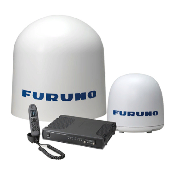
- Page 1 OPERATOR'S MANUAL INMARSAT FLEETBROADBAND FELCOM251 FELCOM501 Model www.furuno.com...
- Page 2 ・FURUNO Authorized Distributor/Dealer 9-52 Ashihara-cho, Nishinomiya, 662-8580, JAPAN A : MAR 2019 Printed in Japan All rights reserved. A2 : JUN . 24, 2019 Pub. No. OME-57050-A2 ( REFU ) FELCOM251/501 0 0 0 1 9 5 8 8 8 1 0...
- Page 3 How to discard a used battery Some FURUNO products have a battery(ies). To see if your product has a battery, see the chap- ter on Maintenance. Follow the instructions below if a battery is used. Tape the + and - terminals of battery before disposal to prevent fire, heat generation caused by short circuit.
- Page 4 SAFETY INSTRUCTIONS Read these safety instructions before you operate the equipment. Indicates a condition that can cause death or serious injury if WARNING not avoided. Indicates a condition that can cause minor or moderate injury if CAUTION not avoided. Warning, Caution Prohibitive Action Mandatory Action WARNING...
- Page 5 10W/m 1.3 m 0.6 m Warning Label Warning label is attached to the equipment. Do not remove the label. If the label is lost or damaged, contact a FURUNO dealer about replacement. Name: Name Plate Type: 16-025-3525-0 Code No.: 100-422-940-10...
- Page 6 505 Emergency Call In the event of an emergency, do the following to make an emergency call: Note: 505 emergency calling is an INMARSAT service and is not GMDSS compliant. 1. At the main screen, press the key. The [Call] screen appears. 2.
- Page 7 505 Emergency Call 6. When the RCC responds, follow the below procedure, speaking clearly and slowly. MAYDAY-MAYDAY-MAYDAY OWN ID This is SHIP’S NAME: ________________ NAME-NAME-NAME CALLSIGN: ___________________ CALLSIGN or other IDENTIFICATION MMSI MMSI: _______________________ MAYDAY NAME of the VESSEL in distress CALLSIGN or other IDENTIFICATION MMSI POSITION...
- Page 8 32/38/39 Urgency Call The following short codes are available for urgency calls: • 32: Urgency Medical Advice • 38: Urgency Medical Assistance • 39: Urgency Maritime Assistance Note 1: 32/38/39 urgency calling is an INMARSAT service and is not GMDSS compliant. Note 2: 32/38/39 urgency calling requires a safety voice contract with your service provider and also requires connection to the Alarm Panel (available as an optional extra).
-
Page 9: Table Of Contents
TABLE OF CONTENTS FOREWORD ........................xi SYSTEM CONFIGURATION ..................xv BASIC OPERATION ....................1-1 1.1 Communication Unit and IP Handset Overview ............1-1 1.1.1 Communication Unit ..................1-1 1.1.2 IP Handset......................1-1 1.2 SIM Card ........................1-3 1.3 Power On/Off......................1-4 1.4 Screen Layout ......................1-8 1.5 Basic Operation of the IP Handset ................1-9 1.5.1 Menu operations overview ................1-9 1.5.2... - Page 10 TABLE OF CONTENTS 3.5 IP Handset Information ....................3-8 3.5.1 How to display the system information............3-9 3.5.2 How to display the call restrictions ............... 3-10 3.6 Administrator Settings ....................3-11 3.6.1 Network settings................... 3-12 3.6.2 How to set the phone functions for the IP Handset........3-14 3.6.3 How to set the call restrictions ..............
- Page 11 TABLE OF CONTENTS 6.4 Alternative MS-ISDN Settings ..................6-7 6.4.1 How to register the alternative MS-ISDN ............6-7 6.4.2 How to edit the alternative MS-ISDN..............6-9 6.4.3 How to delete the alternative MS-ISDN............6-9 6.5 PBX Settings ......................6-10 6.5.1 How to set the automatic timeout function ...........6-10 6.5.2 How to set internal call routing ..............6-10 6.6 LAN Settings......................6-12...
- Page 12 TABLE OF CONTENTS APPENDIX 1 MENU TREE ..................AP-1 APPENDIX 2 LIST OF TERMS AND ABBREVIATIONS........AP-5 APPENDIX 3 NOTIFICATION MESSAGES .............AP-8 SPECIFICATIONS .....................SP-1 INDEX.......................... IN-1...
-
Page 13: Foreword
A Word to the Owner of the FURUNO FELCOM251/501 Congratulations on your choice of the FURUNO FELCOM251/501 Inmarsat Fleetbroadband Ship Earth Station. We are confident you will see why the FURUNO name has become synonymous with quality and reliability. Since 1948, FURUNO Electric Company has enjoyed an enviable reputation for quality marine electronics equipment. - Page 14 • 192.168.1.0 to 192.168.13.0 • 192.168.50.1 to 192.168.93.1 • 192.168.61.1 to 192.168.61.44 CE declaration With regards to CE declarations, please refer to our website (www.furuno.com) for further infor- mation about RoHS conformity declarations. Licensing and Copyright information Aes-2014-03-10 Copyright (c) 2003, Dr Brian Gladman, Worcester, UK. All rights reserved.
- Page 15 FOREWORD eCos-3.0.12 Copyright (c) 1999 Kungliga Tekniska Hogskolan (Royal Institute of Technology, Stockholm, Swe- den). Copyright (c) 1980, 1982, 1985, 1986, 1988, 1989, 1990, 1991, 1992, 1993, 1994, 1995 The Re- gents of the University of California. (c) UNIX System Laboratories, Inc. Copyright 1994, 1995 Massachusetts Institute of Technology.
- Page 16 FOREWORD ppp-custom Copyright (c) 1991 Gregory M. Christy. All rights reserved. Redistribution and use in source and binary forms are permitted provided that the above copyright notice and this paragraph are duplicated in all such forms and that any documentation, advertising materials, and other materials related to such distribution and use acknowledge that the software was developed by Gregory M.
-
Page 17: System Configuration
SYSTEM CONFIGURATION FELCOM501 FELCOM251 Antenna Unit Antenna Unit FB-1501 FB-1251 Telport Extender FB-3002 GS Facsimile GS Facsimile Analog Telephone Analog Telephone GS Facsimile Analog Telephone (Up to 4 connections) Communication Unit FB-2001 12-24V DC Relay RT3SP1-12V AC/DC Power External Alarm... - Page 18 SYSTEM CONFIGURATION Caution when connecting shipboard network to FELCOM251/501 If the FELCOM251/501 is connected to a shipboard network that has a data monitoring system or the like, the FELCOM251/501 can become unstable when the equipment in the network transmits large volumes of broadcast packets. If this type of shipboard network is connected to the FEL- COM251/501, consultation with the network system manager is necessary to provide measures to ensure the FELCOM251/501 operates stably.
-
Page 19: Basic Operation
BASIC OPERATION Communication Unit and IP Handset Overview 1.1.1 Communication Unit SIM card slot Power switch 1.1.2 IP Handset Speaker Screen Enter Microphone Function • Opens the [Volume] screen. • Softkey (Lower left menu item button) • Opens the [Contacts] list/call history. •... - Page 20 1. BASIC OPERATION Function • Moves the cursor down. • Decreases the volume. • On main screen: decrease the brilliance. Note: On screens other than the main screen, hold the 0 key and press to decrease the brilliance. Moves the cursor left. Moves the cursor right Enter •...
-
Page 21: Sim Card
1. BASIC OPERATION SIM Card Note: The FELCOM251/501 uses only Inmarsat Fleetbroadband compatible SIM cards. Individual user information is stored on the SIM card. The system reads information when the SIM card is inserted. The user registration number is saved on the SIM card, and it is possible to transmit with different SIM cards from one terminal. -
Page 22: Power On/Off
1. BASIC OPERATION Power On/Off How to turn on The POWER switch on the front panel of the Communication Unit switches the follow- ing units on/off: • IP Handset • Communication Unit • Antenna Unit • Alarm Panel (option) 1. By hand, peel the card slot cover from the right end on the front of the Communi- cation Unit to show the SIM card port. - Page 23 1. BASIC OPERATION 5. Turn on the power switch on the Communication Unit. IP Handsets connected to the Communication Unit can take up to 40 seconds to power up and show the start-up screen. xx.xx Wait approximately three minutes for the main screen to display. When the main screen Shows the icons in green on the status bar, communication is possible.
- Page 24 1. BASIC OPERATION If the PIN code is locked If the wrong PIN code is input three times, the current PIN number becomes locked and the following screen appears. Do the procedure below to unlock the PIN code. 1. Press to select the [Username] field, then press the Enter key.
- Page 25 1. BASIC OPERATION If the wrong PUK code is input ten times, the current PUK number becomes locked and the following screen appears. IP Handset and Web interface operational ability The following operations are possible using the IP Handset and Web interface: Item Web interface Handset...
-
Page 26: Screen Layout
1. BASIC OPERATION Screen Layout IP Handset Screen Status bar *1: Processing Ready Time Voice (Voice line in use) Fax (Fax in use) ISDN (ISDN in use) Date (UTC or local) *2: Not connected Ship latitude Connected Ship longitude Processing Satellite in use Voice status *1 No permission... -
Page 27: Basic Operation Of The Ip Handset
1. BASIC OPERATION Basic Operation of the IP Handset 1.5.1 Menu operations overview 1. At the main screen, press the Enter key to open the main menu. The IP Handset main menu has six items: [Contents], [Comm. Unit], [Notifica- tions], [Info], [Settings], and [Admin]. Cursor (Blue highlight) Select with the corresponding key. - Page 28 1. BASIC OPERATION 4. In the selected menu, press to choose a menu item, then press the Enter key to open the item. As an example, the [Display] menu is shown below. 5. In the selected menu, press to choose a menu item, then press the Enter key to open the item.
-
Page 29: How To Input Characters
If the cursor is on a character, press to move .(period) the cursor right. Example of text input For example, to input "furuno" at the text input screen, do the following: Entered/available character count Input mode abAB: Alphabet 1234: Numeric : Change input mode 1. -
Page 30: How To Edit Text
1. BASIC OPERATION 1.5.3 How to edit text Edit text at the text input screen. 1. At the text input screen, put the cursor on the text to correct. 2. Press . One character erases. Note: To erase all characters to the right of the cursor, press and hold the key. -
Page 31: Ip Handset Operations
IP HANDSET OPERATIONS Note: This equipment uses SIP/RTP for data transfer and calls. These protocols are not encrypted and may be intercepted in an unsecured environment. Ensure that the network used for connection is secure and monitored in order to prevent interception of important data/information. - Page 32 2. IP HANDSET OPERATIONS prefix is input, the call is place based on the setting for [Outgoing Service] on the [Phone List] screen (see section 6.2). Depending on SIM card contract, "3.1kHz Audio" cannot be used. Contact the company which issues your SIM card for details. Display on main Service Charge...
- Page 33 5. Press the key to go back to the main screen. Note: To place a phone call from land to the FELCOM251/FELCOM501, dial the iden- tification code of the phone carrier, [870] (ocean area code) then the Inmarsat number. How to call from the [History] screen A number can be dialed directly from the [History] screen.
- Page 34 2. IP HANDSET OPERATIONS Icon Error code (Shown only when an error occurs.) Phone number (Displays name if registered in [Contacts] list.) Day/month, time Communication time Press the key to return to the [History] screen. If you call the number, press the Enter key, then go to step 6.
-
Page 35: Operation During Communication
2. IP HANDSET OPERATIONS Name of party Phone number Speed dial number Press the key to return to the [Contacts] list. If you call the contact, press the Enter key, then go to step 4. 4. Press the key to place a call. 5. - Page 36 2. IP HANDSET OPERATIONS How to put a call on hold It is possible to put a call on hold during the conversation. 1. During a conversation, press the key. XXXXXX If the other party puts a call on hold during an internal call, the title of the screen Shows "Held"...
-
Page 37: How To Answer A Call
2. IP HANDSET OPERATIONS 2.1.3 How to answer a call 1. When the IP Handset rings, release the IP Handset from the cradle. If the handset is not cradled when the call is received, press the key. If the call is from one of the subscribers described below, the name of the caller appears. -
Page 38: Hands-Free Function
2. IP HANDSET OPERATIONS 2.1.4 Hands-free function The hands-free function lets you make or answer calls, without holding the handset. This leave your hands free to do other important tasks, like steering your vessel. To activate the hands-free function, press the key with the IP Handset on the cra- dle when you make or answer a call. -
Page 39: Contacts] List
2. IP HANDSET OPERATIONS [Contacts] List Frequently called numbers can be saved in the [Contacts] list for easy access when phoning. The contacts are saved in the Communication Unit. The [Contacts] list can store 200 contacts. 2.2.1 How to add a contact Add a contact (name, phone number, and speed dial) to the [Contacts] list as follows: 1. -
Page 40: How To Search For A Contact
2. IP HANDSET OPERATIONS 5. Input a name of a party, then press the Enter key. You can use a maximum of 20 characters. For how to input the name, see section 1.5.2. 6. Press to select the [Number] field, then press the Enter key. 7. - Page 41 2. IP HANDSET OPERATIONS 6. Press to select [Search], press the Enter key to perform the search. The results of the search appear on the [Search Results] screen. If the contact cannot be found, the message "Not found." appears. Note: If the search is performed with nothing input in the field at step 5, all the con- tacts appears in alphanumeric order.
-
Page 42: How To Edit A Contact
2. IP HANDSET OPERATIONS 2.2.3 How to edit a contact You can edit a contact registered in the [Contacts] list. 1. At the main screen, press the key to open the [Contacts] list. 2. Press to select a contact to edit. 3. -
Page 43: How To Delete A Contact
2. IP HANDSET OPERATIONS 2.2.4 How to delete a contact This section explains how to delete a contact registered in the [Contacts] list as fol- lows:. • How to delete an individual contact • How to delete all the contacts How to delete an individual contact 1. -
Page 44: History] Screen
2. IP HANDSET OPERATIONS [History] Screen Up to 20 calls can be stored in the IP Handset. When the 21st call occurs, the oldest logged call is deleted from the list. To access the [History] screen, press the key followed by Status icons Date and time of call : Received... -
Page 45: How To Delete A History
2. IP HANDSET OPERATIONS 2.3.2 How to delete a history This section explains how to delete a history stored in the IP Handset as follows: • How to delete an individual history • How to delete all the histories How to delete an individual history 1. -
Page 46: Rescue Call
2. IP HANDSET OPERATIONS Rescue Call There are two kinds of rescue calls as follows. • Emergency call (505) • Urgency call (32/38/39) Note: Emergency calling and urgency calling are an INMARSAT service and is not GMDSS compliant. 2.4.1 Emergency call (505) There are two methods to place the emergency call: •... - Page 47 2. IP HANDSET OPERATIONS How to call from the [Emergency Call] screen 1. At the main screen, press the key. The [Call] screen appears. 2. Press the key to open the sub-menu. 3. Press to select the [Rescue Call] menu, then press the Enter key. Safety Voice handset screen Other handset screen If your IP Handset is not a Safety Voice Handset, go to step 5.
-
Page 48: Urgency Call (32/38/39)
2. IP HANDSET OPERATIONS 2.4.2 Urgency call (32/38/39) The following short codes are available for urgency calls: • 32: Urgency Medical Advice • 38: Urgency Medical Assistance • 39: Urgency Maritime Assistance Note 1: 32/38/39 urgency calling requires a safety voice contract with your service provider and also requires connection to the Alarm Panel (available as an optional ex- tra). -
Page 49: Notification Log
2. IP HANDSET OPERATIONS 4. Press to select [Medical Advice], [Medical Assist], or [Maritime Assist] menu, then press the Enter key. For [Medical Advice] For [Medical Assist] For [Maritime Assist] 5. Press to select the [Call (32)], [Call (32)], or [Call (39)] menu. Notification Log You can display the events occurred in the system. -
Page 50: Prefix Settings
2. IP HANDSET OPERATIONS 3. Select an event to view the complete information. Date and time of event Event code Event contents Recommended action Press the key or key to return to the event log screen. 4. Press the key to close the event log screen. Prefix Settings You can set the sound quality and the caller code for each outgoing call. -
Page 51: Settings For Ip Handset
SETTINGS FOR IP HANDSET This chapter describes the menus [Sounds], [Display], [Time], [Comm. Unit], [Info], and [Admin]. Sound Settings You can set the volume and ring tone. 1. At the main screen, press the Enter key to open the main menu. 2. -
Page 52: How To Change The Ring Tone
3. SETTINGS FOR IP HANDSET 3.1.2 How to change the ring tone You can set the ring tone for external/internal incoming call, and notification. 1. In the [Sounds] menu, press to select the [Ring Tome] menu, then press the Enter key. The [Ring Tone] screen appears. -
Page 53: How To Change The Font Size
3. SETTINGS FOR IP HANDSET 3.2.1 How to change the font size 1. In the [Display] menu, press to select the [Font Size] menu, then press the En- ter key. The [Font Size] screen appears. 2. Press to select the font size ([Small] or [Large]), then press the Enter key. The font size is shown in the [Sample] area. -
Page 54: Time Zone Settings
3. SETTINGS FOR IP HANDSET Time Zone Settings You can display the time and date in UTC format or as local time. 1. At the main screen, press the Enter key to display the main menu. 2. Press to select the [Settings] menu, then press the Enter key. 3. -
Page 55: How To Use Local Time
3. SETTINGS FOR IP HANDSET 3.3.2 How to use local time To use local time, do the following: 1. In the [Time] screen, press to select the [Time Offset] field. 2. Press to select [ON]. 3. Press to select the [UTC] field for hour. 4. -
Page 56: How To Display The [Status] Screen
3. SETTINGS FOR IP HANDSET 3.4.1 How to display the [Status] screen You can display the six status; SIM, IMSI, satellite, beam number, beam level, and ship position. 1. In the [Comm. Unit] menu, press to select the [Status] menu, then press the Enter key. -
Page 57: How To Search For A Satellite
3. SETTINGS FOR IP HANDSET 3.4.2 How to search for a satellite Note: Satellite settings are saved inside the Communication Unit. You can also ac- cess these settings from the Web interface (see section 5.7). You can set to automatically or manually search and track satellites. 1. -
Page 58: How To Connect/Disconnect The Data Line
3. SETTINGS FOR IP HANDSET 3.4.3 How to connect/disconnect the data line You can connect or disconnect a data line of a WAN group to which IP Handset be- longs. You can check with the Web interface to which group your IP Handset belongs. Note 1: When Fleet Xpress mode is active, this menu is not available. -
Page 59: How To Display The System Information
3. SETTINGS FOR IP HANDSET 3.5.1 How to display the system information 1. In the [Information] menu, press to select the [IP Handset Info] menu, then press the Enter key. The [IP Handset Info.] screen appears. Press to scroll through the information. Press the key to update the status. -
Page 60: How To Display The Call Restrictions
3. SETTINGS FOR IP HANDSET 3.5.2 How to display the call restrictions 1. In the [Information] menu, press to select the [Restrictions] menu, then press the Enter key. The [Restriction] screen appears. item Description External Call Shows the setting to permit or prohibit the outside line ([Enabled] or [Disabled]). -
Page 61: Administrator Settings
3. SETTINGS FOR IP HANDSET Administrator Settings This section covers how to access the advanced settings for the IP Handset. User must login as Administrator to access these functions. Note: Communication may not be possible if setting are wrong. Settings should be performed by an experienced administrator. -
Page 62: Network Settings
3. SETTINGS FOR IP HANDSET 3.6.1 Network settings You can make the network settings for the IP Handset and the Communication Unit. For IP Handset 1. In the [Admin Settings] menu, press to select the [Network] menu, then press the Enter key. The [Network] menu appears. - Page 63 3. SETTINGS FOR IP HANDSET 8. Press to select a cell to input the subnet mask. 9. Press the 0 to 9 key to input a part of the subnet mask in the cell. 10. Repeat steps 9 and 10 to input the subnet mask in the cells. 11.
-
Page 64: How To Set The Phone Functions For The Ip Handset
3. SETTINGS FOR IP HANDSET 8. Press the Enter key to confirm the setting. The following screen appears. Applied. 9. Press the key to go back to the main screen. 3.6.2 How to set the phone functions for the IP Handset This section explains the following contents: •... - Page 65 3. SETTINGS FOR IP HANDSET 2. With [Number] selected, press the Enter key. The [Phone Number] screen appears. 3. Press to select the [Number] field, then press the Enter key. The list of the extension numbers available appears. 4. Press to select the extension number, then press the Enter key.
- Page 66 3. SETTINGS FOR IP HANDSET 2. Press to select the [Echo Cancel] menu, then press the Enter key. 3. Press to select [OFF] or [ON], then press the Enter key. 4. Press the key to go back to the main screen. 3-16...
-
Page 67: How To Set The Call Restrictions
3. SETTINGS FOR IP HANDSET How to set the noise cancel Turn the noise cancel on to reduce unwanted ambient sounds. Do the following to turn echo cancel on or off: 1. In the [Admin Settings] menu, press to select the [Phone] menu, then press the Enter key. - Page 68 3. SETTINGS FOR IP HANDSET 2. With [Ext Call Limit] selected, press the Enter key. 3. Press to select [Enabled] or [Disabled], then press the Enter key. • Enabled: Permits external calls. • Disabled: Prohibits external calls. The message "Wait response..." appears, followed by "Request completed. Check the status."...
- Page 69 3. SETTINGS FOR IP HANDSET How to set the outside call filter If the filter has been activated, the user is restricted to call the destination only set in the Web interface. See section 6.2 how to set the outside call filter. Note: [Caller Code] must be [No Request] to use this function.
-
Page 70: How To Transfer The Syslog To A Pc
3. SETTINGS FOR IP HANDSET 3.6.4 How to transfer the syslog to a PC You can transfer the syslog to a PC installing the syslog application. 1. In the [Admin Settings] menu, press to select the [Syslog Transfer] menu, then press the Enter key. -
Page 71: Optional Devices
FAX number. When replying to a FAX, be sure to ask the sender for their FAX number. Note 2: When you send a fax from FELCOM251/501 to FELCOM30/50/70, always use a 3.1 Khz audio service number. - Page 72 4. OPTIONAL DEVICES This page is intentionally left blank.
-
Page 73: Web Interface
• http://192.168.0.1/ This is the factory default IP address. If the IP address was not changed at in- stallation, use this method. • http://furuno.fb.ut This access method requires the PC-side DNS to be set as the Communication Unit’s IP address. - Page 74 5. WEB INTERFACE 6. If your SIM card requires a PIN code, the PIN input window shown below ap- pears. For SIM cards with no PIN code requirement, the top page of the Web interface appears. Skip to step 7. How to input the PIN code 1) Input the PIN code (4 to 8 digits) in the [PIN code] field.
- Page 75 5. WEB INTERFACE If the wrong PUK code is input ten times, the current PUK number becomes locked and the following pop-up window appears. 7. The top page of the Web interface is [Dashboard], located in the [Home] menu. Error Warning For how to use the Web interface, see section 5.2.
-
Page 76: How To Use The Web Interface
The top page of the Web interface is divided into several areas. Most of the screen- shots in this manual are taken from the FELCOM501. Screens may be slightly differ- ent on the FELCOM251 due to differences in data communications service. Signal strength area... - Page 77 5. WEB INTERFACE System message area System errors and other events appear in the system message area. The messages are listed in order from highest to lowest level of priority as follows: Priority Icon Description SIM error SIM is not available. Error There is a problem which may affect equipment startup and operation.
- Page 78 5. WEB INTERFACE Date and time area The date and time area shows the date and time. Menu bar The menu bar contents change depending on your login level (Log user, Administrator or standard user). Click a menu item with the mouse pointer to view the contents in the sub menu or information area.
-
Page 79: Dashboard
5. WEB INTERFACE Dashboard The dashboard is the default start-up menu for the Web Interface and shows satellite tracking status, GPS status, notifications, communication status, ongoing calls, ongo- ing data session, and LAN status. All information is refreshed every five seconds when the automatic update function is active. - Page 80 5. WEB INTERFACE Item Description Beam Number Shows satellite beam number currently in use. Signal strength Shows signal reception level detected at the Communication Unit. GPS Status GPS Tracking Status Shows the GPS tracking status: • Acquiring • Acquired • Stored (Temporally using the GPS data previously stored in the Communication Unit when GPS signal is lost.) Latitude Shows ship latitude.
-
Page 81: Data Connection
5. WEB INTERFACE Data Connection There are two types of IP packet communication services: Connection Payment Service Description speed method Standard IP Speed of the commu- • Max. 284 kbps Fee based on • E-mail (Best effort nication service is not (FELCOM 251) amount of data •... - Page 82 5. WEB INTERFACE Item Description Group Name Shows the WAN group name. Shows "P" when the primary data connection for each group is activat- Service Name Shows the following type of data communication service. • Standard data • 8 kbps Streaming, 16 kbps Streaming, 32 kbps Streaming, 64 kbps Streaming, 128 kbps Streaming, or 256 kbps Streaming* *: FELCOM501 only Application...
-
Page 83: How To Disconnect From The Internet
5. WEB INTERFACE For example, in the connection list shown in the previous example figure, Win- ® dows Media Player uses the 32 kbps streaming IP packet communication ser- vice and all other applications use the standard IP packet communication service. 5.4.2 How to disconnect from the internet Do the following to disconnect from the internet:... -
Page 84: Contacts List
5. WEB INTERFACE Contacts List Like the IP Handset, you can add, edit and delete contacts from the Web interface. Use the Web interface to save contacts to the Communication Unit. 200 contacts can be stored in the Communication Unit. The contacts are shared between the Commu- nication Unit and IP Handset. -
Page 85: How To Search For A Contact
5. WEB INTERFACE 5.5.2 How to search for a contact This section explains how to search for a contact from the contacts list. 1. Click [Contacts] in the menu bar. Search box Search box Search box 2. Input a part of a contact name, phone number, or speed dial number in the search box. -
Page 86: How To Import/Export The Contacts Data
5. WEB INTERFACE 5.5.5 How to import/export the contacts data You can import or export the contacts data. How to export a contact data file Export a contact data file from the Communication Unit to a PC. 1. Click [Contacts] in the menu bar. 2. -
Page 87: Sms (Short Message Service)
5. WEB INTERFACE SMS (Short Message Service) You can create SMS messages from the Web interface. Messages are limited to 1120 characters. Depending on the setting at Encode, the message may be split into segments. For GSM, messages over 160 characters; for Unicode, messages over 70 characters are split. -
Page 88: How To Send An Sms Message
5. WEB INTERFACE 5.6.2 How to send an SMS message You can send an SMS message to the terminal enabled SMS. 1. Click [SMS] in the menu bar. to show the [Inbox] (SMS top screen) menu. 2. Click [Create New Message] in the sub menu to show the [Create New Message] menu. - Page 89 5. WEB INTERFACE c) Click the [Select] button to confirm the selection. Click the [Cancel] button go back to the previous display without selecting. 4. At [Delivery Notification], check, or uncheck the box as required. • Checked: receive a notification when the message is successfully delivered. •...
-
Page 90: How To Review A Received Message
5. WEB INTERFACE 5.6.3 How to review a received message Received messages are saved to the Inbox. 1. Click [SMS] in the menu bar to show the SMS top screen (Inbox). Unread messages appear in bold type. Total (unread) message count Total (unread) message count Total (unread) message count Sender’s phone number. -
Page 91: Message Boxes
5. WEB INTERFACE Operation Procedure Delete the message. 1) Click the [Delete] button. 2) Click the [OK] button. 3) Click [Close] to close the message. View the previous message when Click [ Previous Message]. there are multiple messages. View the next message when there Click [Next Message are multiple messages. -
Page 92: How To Use A Message In The Outbox
5. WEB INTERFACE 5.6.5 How to use a message in the outbox You can edit and resend an already sent message from the outbox. 1. Click [SMS] in the menu bar. 2. Click [Outbox] in the sub menu to show the [Outbox] menu. Total message count Total message count Total message count... -
Page 93: How To Send A Message In The Unsent Box
5. WEB INTERFACE Operation Procedure Delete the message. 1) Click the [Delete] button. 2) Click the [OK] button. 3) Click [Close] to close the message. View the previous message Click [ Previous Message]. when there are multiple messages. View the next message Click [Next Message when there are multiple messages. -
Page 94: How The Show The Original Message In Replies
5. WEB INTERFACE Operation Procedure Send the message 1) Click the [Send] button. 2) Click the [OK] button. Delete the message. 1) Click the [Delete] button. 2) Click the [OK] button. 3) Click [Close] to close the message. View the previous Click [ Previous Message]. -
Page 95: Satellite Search
5. WEB INTERFACE Satellite Search You can set to automatically or manually search and track satellites. 1. Click [Home] in the menu bar. 2. Click [Satellite Selection] to show the [Satellite Selection] menu. Item Description Sat. ID Satellite ID Name Satellite name Longitude Satellite position (longitude). -
Page 96: Active Notifications
5. WEB INTERFACE Active Notifications You can view the information for the active notifications. 1. Click [Home] in the menu bar. 2. Click [Active Notifications] to show the [Active Notifications] menu. Item Description Notification Code Shows the notification code. Date Date and time of occurrence Origin Location of a notification cause as follows:... -
Page 97: Phone List
5. WEB INTERFACE Phone List The phone list shows the extension number and nickname assigned for each handset. 1. Click [Home] in the menu bar. 2. Click [Phone List] to show the [Phone List] menu. 5.10 WAN User List You can view the information for the WAN user list. To change WAN group settings, see section 6.8. -
Page 98: Log Shows
5. WEB INTERFACE 5.11 Log Shows You can display five logs: notification log, voice call log, data connection log, registra- tion log, and remote access log. When the storage capacity of a log is reached, the oldest entries are erased in order. Capacity for entries No. -
Page 99: How To View The Notification Log
5. WEB INTERFACE 5.11.2 How to view the notification log To view the notification log do the following: 1. Click [Log] in the menu bar. 2. Click [Notification Log] in the sub menu to show the [Notification Log] menu. Item Description Code Notification code... - Page 100 5. WEB INTERFACE 3. Click the [Detail] button to view the notification log’s detailed information. The following information appears in addition to the items shown in the list: Item Description Recommended Shows the recommended action for the event. For events Action which cannot be addressed, or have no rectification method, this appears as "- -".
-
Page 101: How To View The Voice Call Log
5. WEB INTERFACE 5.11.3 How to view the voice call log Do the following to view the voice call log: 1. Click [Log] in the menu bar. 2. Click the [Voice Call Log] sub menu to show the [Voice Call Log] menu. Item Description Date... - Page 102 5. WEB INTERFACE 3. Click the [Detail] button to view the voice call log’s detailed information. The following pop-up window appears. Item Description Direction Shows "Outgoing" or "Incoming". MS-ISDN Number of the alternative MS-ISDN for incoming or outgoing call. "Pri- mary"...
- Page 103 5. WEB INTERFACE How to search for an voice call log 1. Click the [Search] button. The search bar appears. Search bar To hide the search bar, click the [Search] button again. 2. Search the voice call log with one or multiple of the following methods: •...
-
Page 104: How To View The Data Connection Log
5. WEB INTERFACE 5.11.4 How to view the data connection log To view the data connection log do the following: 1. Click [Log] in the menu bar. 2. Click the [Data Connection Log] sub menu to show the [Data Connection Log] menu. - Page 105 5. WEB INTERFACE 3. Click the [Detail] button to view the data connection log’s detailed information. The following pop-up window appears. Item Description Access point name When you use a access point name for SIM, "(SIM)" appears before the access point name Code / Mes- Notification code and its content sage...
- Page 106 5. WEB INTERFACE How to search for an data connection log 1. Click the [Search] button. The search bar appears. Search bar To hide the search bar, click the [Search] button again. 2. Search the data connection log with one or multiple of the following methods: •...
-
Page 107: How To View The Registration Log
5. WEB INTERFACE 5.11.5 How to view the registration log The registration log shows a list of all Inmarsat network registrations. To view the Reg- istration log, do the following: 1. Click [Log] in the menu bar. 2. Click the [Registration Log] in the sub menu to show the [Registration Log] menu. Item Description Date... -
Page 108: How To View The Remote Access Log
5. WEB INTERFACE 5.11.6 How to view the remote access log To view the remote access log do the following: 1. Click [Log] in the menu bar. 2. Click the [Remote Access Log] sub menu to show the [Remote Access Log] menu. - Page 109 5. WEB INTERFACE How to search for an remote access log 1. Click the [Search] button. The search bar appears. Search bar To hide the search bar, click the [Search] button again. 2. Search the data connection log with one or multiple of the following methods: •...
- Page 110 5. WEB INTERFACE This page is intentionally left blank. 5-38...
-
Page 111: Settings On Web Interface
SETTINGS ON WEB INTERFACE This chapter covers how to access Communication Unit settings, and connection in- formation. User must login as Administrator to access these functions. Note: Communication may not be possible if the settings are incorrect. Settings should be performed by an experienced administrator. Also, be sure to log out after changing any settings. -
Page 112: Editing Information For Extension Numbers
6. SETTINGS ON WEB INTERFACE Editing Information for Extension Numbers You can edit the information for extension numbers. 1. Referring to section 6.1, login as an Administrator. 2. Click [Admin] in the menu bar. 3. Click [Telephony Settings]. 4. Click [Phone List] to show the [Phone List] menu. Available/connectable phone count Available/connectable phone count Available/connectable phone count... - Page 113 6. SETTINGS ON WEB INTERFACE Item Description AMS-ISDN Shows " " for the phone is related to alternative MS-ISDN. Call Filter Shows " " for the phone which destination is restricted. S/W Ver Software for the IP Handset 5. Click the [Edit] button at the right side of the extension to edit. 6.
- Page 114 6. SETTINGS ON WEB INTERFACE 11. Set whether to request the caller code in the [Caller code] field. To request the caller code, put a [ ] in the box on the left side of [Required for external call] (click the box to add [ ]). If you do not request the caller code, uncheck the [ ] in the box (click the box to delete [ ]).
-
Page 115: Caller Code Settings
6. SETTINGS ON WEB INTERFACE Caller Code Settings When making an outside call from a terminal of which a box of a caller code is checked, input of “caller code” and “*” before the phone number of the party to call is required. -
Page 116: How To Edit Caller Code
6. SETTINGS ON WEB INTERFACE 8. Click the [Add] button. The message "Applied." appears. Note: An error message appears in the following cases. • When the caller code input in step 6 is already registered, the message "The code is already used." appears. •... -
Page 117: Alternative Ms-Isdn Settings
6. SETTINGS ON WEB INTERFACE Alternative MS-ISDN Settings The alternative MS-ISDN (Mobile Subscriber ISDN Number) function offers multiple telephone numbers with single FBB terminal for Inmarsat. The alternative MS-ISDN service is available with a contract for the service by your service provider. Note: The alternative MS-ISDN allows the user to assign maximum eight telephone numbers (alternative MS-ISDN) to a specific terminal in addition to the main telephone number. - Page 118 6. SETTINGS ON WEB INTERFACE 4. Click [Alternative MS-ISDN] to show the [Alternative MS-ISDN] menu. Registered/available alternative MS-ISDN count Registered/available alternative MS-ISDN count Registered/available alternative MS-ISDN count 5. Click the [Add MS-ISDN] button. 6. Input an alternative MS-ISDN which is provided by your service provider in the [Al- ternative MS-ISDN] field (maximum 12 characters).
-
Page 119: How To Edit The Alternative Ms-Isdn
6. SETTINGS ON WEB INTERFACE 6.4.2 How to edit the alternative MS-ISDN Edit the alternative MS-ISDN as follows: Note: When you change (or delete) the settings of the associated extensions, the ex- tension shown on the [Alternative MS-ISDN] menu is changed (or deleted) according- 1. -
Page 120: Pbx Settings
6. SETTINGS ON WEB INTERFACE PBX Settings 6.5.1 How to set the automatic timeout function The automatic timeout function automatically disconnects a voice call (with the excep- tion of emergency call type 505, urgency call 32/38/39, Inmarsat special numbers, ex- tension numbers and Distress calls) when the receiver is left off the hook for the specified number of period of time. - Page 121 The message "Applied." appears. 9. Click the [Close] button to close the message. When a voice call is received, the FELCOM251/501 plays guidance to the calling par- ty. Then, the calling party inputs an extension number. The call is then transferred to that number.
-
Page 122: Lan Settings
6. SETTINGS ON WEB INTERFACE LAN Settings The LAN Settings must be performed by the network manager. Note: After making any changes to network settings, conduct a ping test for the net- work address and broadcast address and check that there is no packet amplification. 6.6.1 How to set up the network 1. -
Page 123: How To Set Up The Dhcp Lease
6. SETTINGS ON WEB INTERFACE 7. Click the [Apply] button. The message "Restart the system to apply the changes." appears. Click the [OK] button. The message "Restart the system to apply the changes." appears. 9. Click the [Close] button to close the message. Restart the equipment to apply the settings. -
Page 124: How To Set Up The Static Routing
6. SETTINGS ON WEB INTERFACE 6.6.3 How to set up the static routing Static routing allows to forward packets via a local router which is connected to the Communication Unit. To setup static routing, do the following: 1. Referring to section 6.1, login as an Administrator. 2. -
Page 125: Isdn Settings
6. SETTINGS ON WEB INTERFACE ISDN Settings Set for the equipment that is connected to the USB port via "USB-RS232C Converter". 1. Referring to section 6.1, login as an Administrator. 2. Click [Admin] in the menu bar. 3. Click [ISDN Settings] to show the [ISDN Settings] menu. 4. -
Page 126: Wan Settings
6. SETTINGS ON WEB INTERFACE WAN Settings The FELCOM251/501 provides multiple WAN groups which have independent data connection with different filtering policy for the connected equipment. So you can make your own groups, like a group for business use and a group for private use. The network administrator is responsible for the group/network design. -
Page 127: How To Register/Edit Wan Group As "Router Mode
6. SETTINGS ON WEB INTERFACE 6.8.1 How to register/edit WAN group as “Router mode” Router mode is the more common of the connection types, allowing data transfer and automatic connection at startup. You can also manually connect from the WEB inter- face, as well as from a handset. - Page 128 6. SETTINGS ON WEB INTERFACE Item Description Connection Type Shows "Router mode". Group Name Shows the registered group name. Connection List Add connection Create a new connection. Up to ten connections can be created. button Delete button Delete the item having a checkmark [ ]. Put a [ ] in the box on the left side of the item to delete.
- Page 129 6. SETTINGS ON WEB INTERFACE When clicking the [Save] button, the connection is added to the connection list as follows: To edit the created connection, Click the [Edit] button. Edit the connection, referring to the table at this step. 8. Click the [Next] button. Registered/available count Registered/available count Registered/available count...
- Page 130 6. SETTINGS ON WEB INTERFACE 10. Referring to the following table, set up the user for using the WAN connection. Input the IP address of the network equipment to enable data communication. If an IP address of an IP Handset is not registered as "User" here, "No permission" appears on the main screen of the IP Handset.
- Page 131 6. SETTINGS ON WEB INTERFACE 12. Referring to the table below, set up the WAN connection settings. Item Description Connection Type Shows the registered connection type. Group Name Shows the registered group name. Put a [ ] in the box to use Access Point Name in the SIM card. Use ASC II characters (other than “, ’) for the names of connec- tion destinations (maximum 100 characters).
-
Page 132: How To Register/Edit Wan Group As "Pppoe
6.8.2 How to register/edit WAN group as "PPPoE" The FELCOM251/501 can connect (dial-up connection) to the internet via PPPoE. With the Web interface and PC set up for PPPoE, the dial-up application directly con- trols connection and disconnection of the data line. (It is not necessary to boot the Web interface to connect to the internet.) The PPPoE settings must be done by the... - Page 133 6. SETTINGS ON WEB INTERFACE 5. Click the [Next] button. 6. Referring to the following table, set up the PPPoE connection settings and choose a service name. Item Description Connection Type Shows "PPPoE". Group Name Shows the registered group name. Connection List PPPoE Username Input the user name*...
- Page 134 6. SETTINGS ON WEB INTERFACE 7. Click the [Next] button. 8. Referring to the table below, set up the WAN connection settings. Item Description Connection Type Shows "PPPoE". Group Name Shows the registered group name. Put a [ ] in the box to use Access Point Name in the SIM card. Use ASC II characters (other than “, ’) for the names of connec- tion destinations (maximum 100 characters).
- Page 135 6. SETTINGS ON WEB INTERFACE PC settings ® Note: The following procedure uses Windows 10 for screenshots. If your PC is using ® ® a different Windows version, see your Windows manual for the correct method to access the network settings. First set the PPPoE information on the Web interface, then set it on the PC.
- Page 136 6. SETTINGS ON WEB INTERFACE 4. Select [Connect to the Internet], then click the [Next] button. 5. Click [Broadband (PPPoE]. 6. Input the [Username] and [Password] according to the PPPoE settings (see step 6 in section 6.8.2). 7. You may rename the connection using the [Connection name] field. Renaming the connection is optional.
- Page 137 The system will now attempt to connect to the internet. On successful connection, a window similar to the one shown below appears. Note: If DNS is blocked by the DNS filter of the FELCOM251/501, the connection test will be failed.
- Page 138 6. SETTINGS ON WEB INTERFACE How to connect to the internet via PPPoE ® Note: The following procedure uses Windows 10 for screenshots. If your PC is using ® ® a different Windows version, see your Windows manual for the correct method to access the network settings.
- Page 139 6. SETTINGS ON WEB INTERFACE 3. Click the appropriate PPPoE network connection. 4. Click the [Connect] button. 5. Input the PPPoE user name and password, then click the [OK] button. Your computer should now be connected to the internet. How to disconnect from a PPPoE connection To disconnect from a PPPoE connection, do the following: 1.
-
Page 140: How To Register/Edit Wan Group As "Bridge
6. SETTINGS ON WEB INTERFACE 6.8.3 How to register/edit WAN group as "Bridge" The "Bridge" mode assigns the WAN IP address provided by Inmarsat to a device con- nected to the specified LAN port on the Communication Unit. The Communication Unit cannot set the NAT, Firewall, IP filter, or DNS filter. - Page 141 6. SETTINGS ON WEB INTERFACE 5. Click the [Next] button. 6. Referring to the following table, set up the LAN port and select a service name. Item Description Connection Type Shows the registered connection type. Group Name Shows the registered group name. Port Select LAN port from [LAN1], [LAN2], [LAN3], and [LAN4].
- Page 142 6. SETTINGS ON WEB INTERFACE 8. Referring to the table below, set up the WAN connection settings. Item Description Connection Type Shows the registered connection type. Group Name Shows the registered group name. Put a [ ] in the box to use Access Point Name in the SIM card. Use ASC II characters (other than “, ’) for the names of connec- tion destinations (maximum 100 characters).
-
Page 143: How To Register/Edit Wan Group As "At Command
6. SETTINGS ON WEB INTERFACE 6.8.4 How to register/edit WAN group as "AT Command" With "AT Command", you can set, connect, or disconnect the data line by the com- mand sent from the device connected to the FELCOM 251/501. 1. Referring to section 6.1, login as an Administrator. 2. - Page 144 6. SETTINGS ON WEB INTERFACE Item Description Connection Type Shows the registered connection type. Group Name Shows the registered group name. User List Add user button Create a new user. Up to 20 users can be created. Delete button Delete the item having a checkmark [ ]. Put a [ ] in the box on the left side of the item to delete.
-
Page 145: How To Set The Firewall
6. SETTINGS ON WEB INTERFACE To edit the created user, Click the [Edit] button. Edit the user, referring to the table at this step. 8. Click the [Finish] button. The message "The group registration was successful. Set the firewall, IP filter and DNS filter as necessary."... -
Page 146: How To Set The Dns Filter
6. SETTINGS ON WEB INTERFACE Item Description Prohibit Windows up- ® Put a [ ] in the box to prohibit Windows Update. date The default setting is "checked". Note 1: This item appears in gray when the [Prohibit DNS Re- quest] setting is activated. - Page 147 6. SETTINGS ON WEB INTERFACE 5. Referring to the following table, set up the DNS filter according to your application and system. Item Description Add filter button Create a new DNS filter. Up to 100 filters can be created. Delete button Delete items with check-marks [ ].
-
Page 148: How To Set The Ip Filter
6. SETTINGS ON WEB INTERFACE 8. Click the [Save] button. The message "Applied." appears. Filtered domains appear in the DNS Filter List. 9. Click the [Close] button to close the message. 6.8.7 How to set the IP filter An IP filter helps to regulate access to/from specified IP addresses. Note: To setup an IP filter, [Group Type] must be set to other than [Bridge]. - Page 149 6. SETTINGS ON WEB INTERFACE Item Description Import button Import the IP filter settings. 1) Click the [Import] button. The message "Overwrite the IP filter list in this group. Are you sure?" appears. 2) Click the [OK] button. The [Open] dialog box appears. 3) Select the zip file of the IP filter settings to import, then click the [Open] button.
- Page 150 6. SETTINGS ON WEB INTERFACE 5. Click [Add filter] button. The following pop-up window appears. 6. Referring to the following table, set up the IP filter according to your application and system. Item Description Action Select the IP filter action from "Pass", "Drop", or "Reject". Select "Pass"...
-
Page 151: How To Setup A Dmz
6. SETTINGS ON WEB INTERFACE 6.8.8 How to setup a DMZ A network DMZ (demilitarized zone) helps to provide a “buffer” of security between your network (LAN, etc) and the internet. Note: To setup a DMZ, [Group Type] must be set to other than [Bridge] or [PPoE]. You can setup a DMZ for your network with the following procedure. -
Page 152: How To Setup A Vpn Pass-Through
6. SETTINGS ON WEB INTERFACE 6.8.9 How to setup a VPN pass-through A VPN pass-through lets you connect to outside VPNs (Virtual Private Network) using IPSec. Note: To setup a VPN pass-through, [Group Type] must be set to other than [Bridge] or [PPoE]. -
Page 153: Communication Statistics
6. SETTINGS ON WEB INTERFACE 6.8.10 Communication Statistics You can view the total packet traffic volume according to the destination IP address in the top 10 in the [Access Statistics] area. Also, you can view the communication speed on a graph in the [Speed Graph] area. The vertical axis of the graph is the speed, and the horizontal axis is the period. -
Page 154: Remote Control
2. Input the file name, then click [Save]. The access statistics/speed graph data is saved in zip format. Remote Control The Remote access lets you access the Web interface of FELCOM251/501 via inter- net. Note: The Remote access settings must be done by the network administrator. -
Page 155: How To Change The Password
6. SETTINGS ON WEB INTERFACE 6.10 How to Change the Password Do the following procedure to change the SMS password, Administrator password, and log password. Memorize each password. If a password is forgotten, contact your dealer. 1. Referring to section 6.1, login as an Administrator. 2. -
Page 156: How To Transfer The Event Log To A Pc
6. SETTINGS ON WEB INTERFACE 6.11 How to Transfer the Event Log to a PC You can transfer the Event Log to a PC with the Syslog application installed. 1. Referring to section 6.1, login as an Administrator. 2. Click [Admin] in the menu bar. 3. -
Page 157: Packet Analysis
6. SETTINGS ON WEB INTERFACE 6.12 Packet Analysis 6.12.1 Packet capturing "Packet capturing" is a function to save packets that pass (send and receive) the se- lected network interface. 1. Referring to section 6.1, login as an Administrator. 2. Click [Admin] in the menu bar. 3. -
Page 158: How To Import/Export Settings Data
6. SETTINGS ON WEB INTERFACE 6.13 How to Import/Export Settings Data You can save (export) the Web interface settings and data, as a backup file, to a PC. The backup file can also be applied to the Web interface. 6.13.1 How to export settings To export Web interface settings data to a PC, do the following: 1. -
Page 159: How To Backup And Restore Settings
6. SETTINGS ON WEB INTERFACE 11. Click the [OK] button. When the import is complete, the message "Completed. Please wait a moment for restarting." appears and the Communication Unit restarts. After the restart is com- plete, the main screen appears. 6.14 How to Backup and Restore Settings 6.14.1... -
Page 160: Sim Card Settings
6. SETTINGS ON WEB INTERFACE 6.15 SIM Card Settings 6.15.1 How to set up the PIN code requirement for SIM card Depending on SIM card settings, it is necessary to input a PIN code when power is turned on. It is possible to update the SIM card settings. 1. -
Page 161: Login Banner Settings
6. SETTINGS ON WEB INTERFACE 6.16 Login Banner Settings The login banner message can be set to appear before the login screen in the IP Handset and Web interface. This feature is handy for sharing important information with crew, etc. as the message appears before they can login. 1. -
Page 162: Discrete I/O Settings
6. SETTINGS ON WEB INTERFACE 6.17 Discrete I/O Settings The I/O interface on the Communication Unit has two configurable I/O pins. You can set up the function of each pin in the Web interface. 6.17.1 How to enable the ignition function The ignition function can be used to turn on/off the Communication Unit by means of an external signal. -
Page 163: How To Setup The Warning/Error Output
6. SETTINGS ON WEB INTERFACE 6.17.2 How to setup the warning/error output Pin 2 acts as a built-in switch in the Communication Unit. Pin 2 can be used to provide an external signal that indicates active warning/error condition(s). You can configure pin 2 to be active ground or active open. - Page 164 6. SETTINGS ON WEB INTERFACE This page is intentionally left blank. 6-54...
-
Page 165: Maintenance And Troubleshooting
MAINTENANCE AND TROUBLE- SHOOTING This chapter describes maintenance and troubleshooting procedures to keep the equipment in good condition and restore normal operation in case of trouble. NOTICE WARNING o not apply paint, anti-corrosive ELECTRICAL SHOCK HAZARD Do not open the equipment. sealant or contact spray to plastic parts or equipment coating. -
Page 166: How To Replace The Fuse
7. MAINTENANCE AND TROUBLESHOOTING How to Replace the Fuse The optional AC/DC Power Supply Unit has fuses to protect the unit from overvoltage (over-current) and internal faults. If the unit cannot be turned on, check if the fuse is blown. If a fuse is blown, determine the cause before replacing the fuse. WARNING Use the proper fuse. -
Page 167: Troubleshooting
7. MAINTENANCE AND TROUBLESHOOTING Status Power LED Terminal LED Antenna LED Warning On/Green On/Yellow On/Yellow Updating software On/Green Flashes slowly Flashes slowly (approx. 2 secs, Blue) (approx. 2 secs, Blue) Troubleshooting If you think the equipment is not operating normally, do the checks in the table below to find the possible causes. - Page 168 7. MAINTENANCE AND TROUBLESHOOTING Symptom Remedy Cannot make external • Check telephone number. call. Land subscriber: [00], country code, tel. no. Ship subscriber: [00], [870], (ocean area code), Inmarsat no. • Check if the IP Handset cable is properly connected to the Communica- tion Unit.
-
Page 169: Diagnostics
Note: Do not unzip the archives. Diagnostics Your FELCOM251/ FELCOM501 contains the diagnostics that check the IP Handset, Communication Unit, and Antenna Unit. The tests are for use by qualified technicians, but you can do the tests to help the qualified technician in troubleshooting. - Page 170 7. MAINTENANCE AND TROUBLESHOOTING 4. Press to select [OK]. The ROM/RAM test starts. Test in progress Test results "– –" means that the test is processing. The results appear as "OK" for normal status, "NG" for abnormal status. 5. Press the Enter key to go to the LCD test. 6.
- Page 171 7. MAINTENANCE AND TROUBLESHOOTING When pressing the Enter key on the "RGB gradation" screen, the screen changes as shown below. 7. Press to select [OK] or [NG], then press the Enter key. The [Key Test] screen appears. 8. Press the Enter key to start the key test. 9.
- Page 172 7. MAINTENANCE AND TROUBLESHOOTING 11. Put the IP Handset on the hook, then confirm that the "On the hook" indication ap- pears in white text. To skip the hook test, press the key. Note that the result of the hook test is "NG".
- Page 173 7. MAINTENANCE AND TROUBLESHOOTING 14. Press the Enter key to go to the sound test. The sound test checks the receiver, speaker, and microphone in the IP Handset. 15. Press the Enter key to check the sounds for the receiver. The receiver starts to sound.
- Page 174 7. MAINTENANCE AND TROUBLESHOOTING 20. Press the Enter key to play back the recording. The icon to the right of the "Mic (Front)" item appear in the recording is played back. When the play back is complete, the next text is automatically started. 21.
-
Page 175: Communication Unit And Antenna Unit Test
7. MAINTENANCE AND TROUBLESHOOTING 7.5.2 Communication Unit and Antenna Unit test The Communication Unit and Antenna Unit can be tested with the Web interface. Con- duct this test when you feel there is a problem with the system, such as being unable to send/receive data. -
Page 176: System Information
To view the system information do the following: 1. Open the Web interface. 2. Click [Home]. 3. Click [System Information] to show the [System Information] menu. FURUNO Item Description Vessel name Shows your vessel name. If you are logged is as an administrator, you can edit the name. -
Page 177: Appendix 1 Menu Tree
APPENDIX 1 MENU TREE Default settings are presented in bold italic text. IP Handset menu tree Main screen Enter key Contacts Contacts History Comm. Unit Status Satellite SAT Selection* (AUTO, APAC, EMEA, AMER, MEAS) Data Line Data Line* (Disconnect, Connect) Notifications Handset Comm. - Page 178 APPENDIX 1 MENU TREE Web interface menu tree Menu bar Home Dashboard Satellite Selection Satellite Selection (AUTO, APAC, EMEA, AMER, MEAS) Satellite List Data Connection System Information Active Notifications Phone List WAN User List Inbox Outbox Unsent Create New Message Include message in reply (On, Off) SMS Settings Delivery notification (On, Off)
- Page 179 APPENDIX 1 MENU TREE Network Groups* Settings Communication Statistics Access Statistics Term (This month, Last month, 2 months ago) Speed Graph Term (1hour, 1day, 1week, 30days, 60days, 90days) Basic Settings Own IP Address IP Address* (192.168.0.1) Subnet mask* (255.255.255.0) DHCP Server Use / Unuse* (Use, Unuse) Lease range* (From: 192.168.0.10;...
- Page 180 APPENDIX 1 MENU TREE Remote Access Control Control Web interface Settings Enable/Disable (disabled) Port Number (1 to 65535) SIM Settings ICCID Require PIN at startup Enable/Disable (default depends on SIM settings) PIN code (default depends on SIM settings) Change PIN Code Current PIN New PIN New PIN (Confirmation)
-
Page 181: Appendix 2 List Of Terms And Abbreviations
APPENDIX 2 LIST OF TERMS AND ABBREVIATIONS Term Meaning Alternating Current AMBE Advanced Multi-Band Excitation. A proprietary speech coding standard developed by Digital Voice Systems Inc. Access Point Name. Destination name for packet communication. Conformite Europeenne, This term signifies that a CE certified product conforms to European health, environmental, and safety regulations. - Page 182 APPENDIX 2 LIST OF TERMS AND ABBREVIATIONS Term Meaning IMEI International Mobile Equipment Identifier. A 15-digit number which indicates the model number, manufacturer, producer, and serial number of cell phones and data cards. IMSI International Mobile Subscriber Identity. Specific number assigned to individual SIM cards.
- Page 183 APPENDIX 2 LIST OF TERMS AND ABBREVIATIONS Term Meaning Packet Switching. A method of communication that separates data into small units (packets) and sends them individually. PIN Unblocked Key. If the PIN is entered incorrectly 3 times the SIM card is blocked.
-
Page 184: Appendix 3 Notification Messages
APPENDIX 3 NOTIFICATION MESSAGES SIM errors/events appear in the IP Handset and in the Web interface of the Communication Unit. The list below shows the notification messages that may appear. Notification priority level is annotated in the "Lvl" column as follows: Warning: "W";... - Page 185 APPENDIX 3 NOTIFICATION MESSAGES Code Lvl BDU/Web UI Message Handset Message Explanation/Remedy 0x8045 Antenna start up failed Antenna start-up The temperature in the Antenna is too low for due to low temperature. failed due to the system to start up. low temperature.
- Page 186 APPENDIX 3 NOTIFICATION MESSAGES Code Lvl BDU/Web UI Message Handset Message Explanation/Remedy 0x1100 High temperature. No High temperature. High temperature. No performance degrade. performance degrade. No performance degrade. 0x9112 The Antenna The Antenna The Antenna temperature is too high. Switch temperature is too high.
- Page 187 APPENDIX 3 NOTIFICATION MESSAGES Code Lvl BDU/Web UI Message Handset Message Explanation/Remedy 0x8056 Incorrect SIM card Incorrect SIM card The type of USIM card inserted in the terminal inserted. inserted. is not correct for your terminal. For example, an USIM card for a land mobile system will not work for a maritime system and vice versa.
- Page 188 APPENDIX 3 NOTIFICATION MESSAGES Code Lvl BDU/Web UI Message Handset Message Explanation/Remedy 0x2900 Found network is not a Found network is Found network is not a valid BGAN network. valid BGAN network. not a valid BGAN Restart the Communication Unit. If the network.
- Page 189 APPENDIX 3 NOTIFICATION MESSAGES Code Lvl BDU/Web UI Message Handset Message Explanation/Remedy 0x10400 Short circuit detected Short circuit Short circuit detected on USB port. Restart on USB port. detected on USB the Communication Unit. And check the port. connected device. If the problem persists, contact your dealer.
- Page 190 APPENDIX 3 NOTIFICATION MESSAGES Code Lvl BDU/Web UI Message Handset Message Explanation/Remedy 0x2000312C 0x2000312D 0x2000312E 0x20003131 0x2000317C 0x20003190 0x20003191 0x20003192 0x20003193 0x20003194 0x20003195 0x20003196 0x20003197 0x20003198 0x20003199 0x2000319A 0x2000319B 0x2000319C 0x2000319D 0x2000319E 0x2000319F 0x200031A0 0x200031A1 0x200031A4 0x200031A5 0x200031A6 0x200031A7 0x200031A8 Call failed.
- Page 191 APPENDIX 3 NOTIFICATION MESSAGES Code Lvl BDU/Web UI Message Handset Message Explanation/Remedy 0x200031F7 0x200031F8 0x200031F9 0x20003201 0x20003244 0x20003258 Call failed. Try again. 0x2000325B 0x2000325C 0x2000325E 0x2000325F 0x200032AF 0x20004001 The connection is The connection is closed because of reaching closed because of the specified data size.
- Page 192 APPENDIX 3 NOTIFICATION MESSAGES Code Lvl BDU/Web UI Message Handset Message Explanation/Remedy 0x10000024 Normal deactivation 0x10000025 QoS not accepted 0x10000026 Activation rejected, Network failure 0x10000027 Reactivation required 0x10000028 Feature not supported 0x10000029 Semantic error in the TFT operation 0x1000002A Syntactical error in the TFT operation 0x1000002B Unknown PDP context...
- Page 193 APPENDIX 3 NOTIFICATION MESSAGES Code Lvl BDU/Web UI Message Handset Message Explanation/Remedy 0x10024101 Reject, reattach required 0x10024102 Connection timeout 0x10024103 Reject, authentication failure 0x10024104 Reject, network invalid 0x10024105 Attach Reject, not allowed 0x10024106 Reject, normal detach 0x10024107 Attach reject, no IMSI 0x10024108 Attach reject, Service request denied...
- Page 194 APPENDIX 3 NOTIFICATION MESSAGES Code Lvl BDU/Web UI Message Handset Message Explanation/Remedy 0x10086302 Establish Reject, congestion 0x10086303 Establish Reject, unsupported IAI version 0x10086304 Establish Reject, unsupported UE class 0x10086305 Establish Reject, USIM required 0x10086306 Establish Reject, physical channel failure 0x10086307 Establish Reject, access Class not allowed...
- Page 195 APPENDIX 3 NOTIFICATION MESSAGES Code Lvl BDU/Web UI Message Handset Message Explanation/Remedy 0x1008631f Deregister, tracked SAT below minimum 0x10086320 Deregister, Lease Group not available 0x10086321 Deregister, Lease Mode handover failed 0x10086322 Deregister, Radio Failure Inmarsat Network specified error. If the 0x10086323 Deregister, problem persists, contact your SIM provider.
- Page 196 APPENDIX 3 NOTIFICATION MESSAGES Code Lvl BDU/Web UI Message Handset Message Explanation/Remedy 0x2580D Diagnostic test for Diagnostic test Diagnostic test for Antenna detects error (No Antenna detects error for Antenna GPS module).Restart the Communication (No GPS module). detects error(s). Unit. If the problem persists, contact your dealer.
- Page 197 APPENDIX 3 NOTIFICATION MESSAGES Code Lvl BDU/Web UI Message Handset Message Explanation/Remedy 0x32100 Diagnostic test for Diagnostic test Diagnostic test for Communication Unit Communication Unit for Comm. Unit detects error (RM DSP).Restart the detects error (RM detects error(s). Communication Unit. If the problem persists, DSP).
- Page 198 APPENDIX 3 NOTIFICATION MESSAGES Code Lvl BDU/Web UI Message Handset Message Explanation/Remedy 0x3840A Diagnostic test for Diagnostic test Diagnostic test for Communication Unit Communication Unit for Comm. Unit detects error (Flash ROM).Restart the detects error (Flash detects error(s). Communication Unit. If the problem persists, ROM).
- Page 199 APPENDIX 3 NOTIFICATION MESSAGES Code Lvl BDU/Web UI Message Handset Message Explanation/Remedy 0x80A7 Signal from terrestrial Signal from terrestrial communication communication systems detected and rejected. systems detected and rejected. 0x20000019 No phone number No phone number available. Make sure there available.
-
Page 200: Specifications
FURUNO FELCOM251/501 SPECIFICATIONS OF INMARSAT FLEETBROADBAND FELCOM251/501 ANTENNA UNIT Antenna type FB-1251 BGAN class 9, maritime mechanical tracking FB-1501 BGAN class 8, maritime mechanical tracking Transmit frequency 1626.5 to 1660.5 MHz and 1668.0 to 1675.0 MHz Receiving frequency 1518.0 to 1559.0 MHz Channel interval 1.25 kHz... - Page 201 FURUNO FELCOM251/501 Analog telephone/telefax 2 ports, optional adapter extends up to 4 ports 1 port, USB2.0, optional adapter converts to RS-232C Output alarm 1 port, contact closure (normal close) w/ external relay SIM card 1 slot POWER SUPPLY Antenna unit FB-1251 22.7 VDC: 1.7 A max., supplied from communication unit...
-
Page 202: Index
INDEX edit contact..........2-12 network settings ........3-12 Access code..........6-4 Administrator password permit/prohibit outside line .....3-17 PIN code locked ........1-6 changing of..........6-45 place a call ..........2-1 entry of ...........3-11 put call on hold .........2-6 search for contact........2-10 Communication unit search for satellite ........3-7 front panel ..........1-1 set echo cancel ........3-15 led lamp guide..........7-2... - Page 203 INDEX data connection log ....... 5-32 delete contact ........5-13 delete SMS message ......5-19 disconnect to internet ......5-11 discrete i/o settings ....... 6-52 edit contact..........5-13 edit extension numbers ......6-2 export contact data file ....5-14 6-44 export settings ........
- Page 204 Il testo completo della dichiarazione di conformità UE è disponibile al seguente indirizzo Internet: Latvian Ar šo Furuno Electric Co., Ltd. deklar , ka augst k min ts radioiek rta atbilst (LV) Direkt vai 2014/53/ES. Pilns ES atbilst bas deklar cijas teksts ir pieejams š d interneta vietn :...
- Page 205 O texto integral da declaração de conformidade está disponível no seguinte endereço de Internet: Romanian Prin prezenta, Furuno Electric Co., Ltd. declar c men ionat mai sus tipul de (RO) echipamente radio este în conformitate cu Directiva 2014/53/UE. Textul integral al declara iei UE de conformitate este disponibil la urm toarea...
Need help?
Do you have a question about the FELCOM251 and is the answer not in the manual?
Questions and answers