Table of Contents
Advertisement
Quick Links
Advertisement
Table of Contents

Subscribe to Our Youtube Channel
Related Manuals for Skov DA 175


Summary of Contents for Skov DA 175
- Page 1 DA 175 actuator Technical User Guide 612521 • 2022-09-28...
- Page 3 Note • All rights belong to SKOV A/S. No part of this manual may be reproduced in any manner whatsoever without the expressed written permission of SKOV A/S in each case.
-
Page 4: Table Of Contents
Wall inlets 2 sides – 2 DA 175 .................... 9 3.2.3 Ceiling inlets 2 sides – 1 DA 175 .................... 9 3.2.4 Wall inlets 1 side with manual opening – 1 DA 175 .............. 10 Mountng the DA 175 ....................... 10 Mounting on wall........................ 12 3.4.1 Solid brick wall ........................... - Page 5 DA 175 actuator 8 Technical data .............................. 28 DA 175 24 V DC ........................ 28 DA 175 230 V ........................... 29 Dimensioned sketch ........................ 30 Technical User Guide...
-
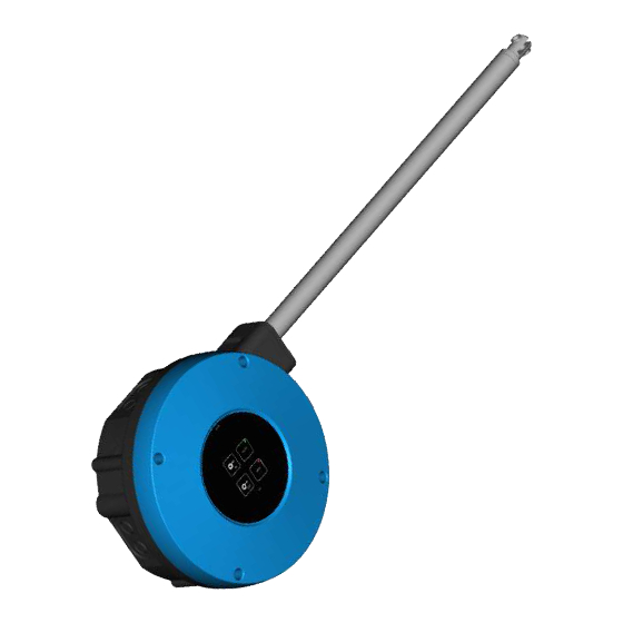
Page 6: Product Description
The actuator can be set with an optional end stop for open- and closed positions. The actuator has a compact design that is easy to clean. The actuator can be controlled manually. When the DA 175 is equipped with 24 V DC, emergency opening is possible through battery power. Technical User Guide... -
Page 7: Product Survey
432112 DA 175-300 actuator 24 V DC 432113 DA 175-600 actuator 24 V DC The DA 175 is used primarily for controlling air intake inlets and can be placed either inside- or outside the livestock house section. Mounting plate and mounting sets must be ordered separately. -
Page 8: Mounting Guide
DA 175 actuator 3 Mounting guide 3.1 Recommended tools Below is a list of tools recommended for assembly. Item Description Cordless drill Drill kit Utility knife Marker pen Multimeter Side cutter Pointed pliers Ladder Screwdriver Socket wrench set Spirit level... -
Page 9: Mounting Examples
DA 175 actuator 3.2 Mounting examples 3.2.1 Wall inlets 2 sides - 1 DA 175 3.2.2 Wall inlets 2 sides – 2 DA 175 3.2.3 Ceiling inlets 2 sides – 1 DA 175 Technical User Guide... -
Page 10: Wall Inlets 1 Side With Manual Opening - 1 Da 175
3.2.4 Wall inlets 1 side with manual opening – 1 DA 175 3.3 Mountng the DA 175 Place the DA 175 approx. 1400 mm above the floor, i.e. so high up that the animals cannot reach it. Make sure that other objects in the livestock house, such as wa- ter pipes, feed pipes, doors, windows, rafters and lighting fixtures do not obstruct the wire drive. - Page 11 DA 175 actuator Use the drilling template to mark holes for the DA 175. Guide for spirit level The drilling template is included in the packaging. Drilling guide 6 x ø10 mm Unscrew the lid and place the lid in service position with a quar- ter turn of the screw.
-
Page 12: Mounting On Wall
DA 175 actuator 3.4 Mounting on wall 3.4.1 Solid brick wall Use 12mm wall dowels and 10mm coach screws. Remember to use the enclosed washers and nylon sealing rings under the screws. Seek to position all six holes within the bricks. -
Page 13: Porous Concrete Wall
Use mounting plate, plough bolts, threaded rods, nuts, and discs. Remember to use the enclosed washers and nylon sealing rings under internal nuts. It is recommended to place the DA 175 near a steel truss as maximum tensile force is 600 kg. Technical User Guide... -
Page 14: Mounting The Cable Gland
3.5 Mounting the cable gland Remove the necessary number of knockouts in the bottom or the side of the DA 175 and mount the cable glands. Mount the cover on the DA 175 by turning the 4 quarter-turn screws. Technical User Guide... -
Page 15: Installation Guide
DA 175 actuator 4 Installation guide Installation, servicing and troubleshooting of all electrical equipment must be carried out by quali- fied personnel in compliance with the applicable national and international standard EN 60204-1 and any other EU standards that are applicable in Europe. -
Page 16: Jumper Setting
DA 175 actuator 4.3 Jumper setting In "dead" mode the jumper on the circuit board can be set so that DA 175 has the desired function. REVERSE = Opposite actuator travel. IN(actuator) Opens inlet IN(actuator) ON/OFF Closes inlet Stepless REVERSE... -
Page 17: General Information About Circuit Diagrams
DA 175 actuator 4.4 General information about circuit diagrams Symbols are in accordance with the IEC/EN 60617 standard. The classification of the symbols ("letter codes") on the symbols is in accordance with the IEC/EN 81346-2 stan- dard. Reference designations are in accordance with IEC/EN 81346-1:2001 structuring principles and reference des- ignations. -
Page 18: Cable Plans And Circuit Diagrams
4.5.1 DA 175 24 V 4.5.1.1 Cable plan For connection, DA 175 24 V is fitted with a 1 m 6 wire cable for the supply and control signals. Insulate conductors that are not connected. Cable dimensions for DA 175 24 V DC depending on length... -
Page 19: Circuit Diagram
DA 175 actuator 4.5.1.3 Circuit diagram DA 175 24 V can be supplied from loop module Q1 to Q5. For power consumption greater than 0.8 A from the loop module, an additional power supply must be used. 4.5.1.4 DA 175 ON/OFF 24 V... -
Page 20: 175 Analog 24 V
DA 175 actuator 4.5.1.6 DA 175 analog 24 V Example of terminal number For correct connection see the setup menu Show connection in the controller Actuator analog 24V Technical User Guide... -
Page 21: 175 230 V
4.5.2 DA 175 230 V 4.5.2.1 Cable plan For connection the DA 175 is fitted with a 1 m 6 wire cable for control signals and a 1 m, 3 wire cable for power supply. Insulate conductors that are not connected. -
Page 22: Circuit Diagram
DA 175 actuator 4.5.2.3 Circuit diagram DA 175 230V is supplied from 230 V. 4.5.2.4 DA 175 ON/OFF 230 V Example of terminal number For correct connection see the setup menu show connections in the controller Winch motor ON/OFF 230V... -
Page 23: 175 Stepless 230 V
DA 175 actuator 4.5.2.5 DA 175 stepless 230 V Example of terminal number For correct connection see the setup menu Show connection in the controller Actuator stepless 24V 4.5.2.6 DA 175 analog 230 V Example of terminal number For correct connection... -
Page 24: User Guide
SET (C) Press and hold SET for 5 seconds and calibration will activate/end. IN (D) For as long as IN is activated, DA 175 will move in until the calibrated end stop has been reached. OUT (E) For as long as OUT is activated, DA 175 will move out until the calibrated end stop has been reached. -
Page 25: Maintenance Instructions
DA 175 actuator 6 Maintenance instructions DA 175 does not require any special maintenance, however, we recommend that the system is serviced once a year. 6.1 Cleaning Clean the product with a cloth that has been wrung out almost dry in water and avoid using: •... -
Page 26: Troubleshooting Guide
DA 175 actuator 7 Troubleshooting guide 7.1 Troubleshooting/remedy Condition/Symptom Green YELLOW Cause/Error Solution Normal operation AUTO Temporary service IMPORTANT: mode Press AUTO for normal operation. Flashing Temporary service MAN - IMPORTANT: slowly* mode, when IN or Motor runs on its own... -
Page 27: Control Signals
DA 175 actuator 7.2 Control signals Control Control + 24 V DC 0-10 V feed- Results supply supply back signal Jumper Cable lead Cable lead Cable lead Cable lead Cable lead Cable lead setting + 24 V DC + 24 V DC... - Page 28 DA 175 actuator 8 Technical data 8.1 DA 175 24 V DC 432110 432111 432112 432113 DA 175-100 DA 175-150 DA 175-300 DA 175-600 Electrical V DC 24 +/-20% Operating voltage Current consumption 0-10 Feedback signal Control signal 0-10 Control signal analog [V] KΩ...
- Page 29 DA 175 actuator 8.2 DA 175 230 V 432114 432115 432116 432117 DA 175-100 DA 175-150 DA 175-300 DA 175-600 Electrical V AC 230 +10%/-20% Rated voltage V AC 195-253 Operating voltage 50/60 Frequency Max. power consumption At 230 V AC supply...
- Page 30 DA 175 actuator 8.3 Dimensioned sketch 937.5 mm ø10 mm 937.5 + 600 mm 6 mm 55 mm 320 mm 6 mm 280 mm 4x ø12.5 Technical User Guide...
- Page 32 SKOV A/S • Hedelund 4 • Glyngøre • DK-7870 Roslev Tel. +45 72 17 55 55 • www.skov.com • E-mail: skov@skov.dk...
Need help?
Do you have a question about the DA 175 and is the answer not in the manual?
Questions and answers