Table of Contents
Advertisement
Quick Links
Advertisement
Table of Contents

Related Manuals for Skov DOL 31


Summary of Contents for Skov DOL 31
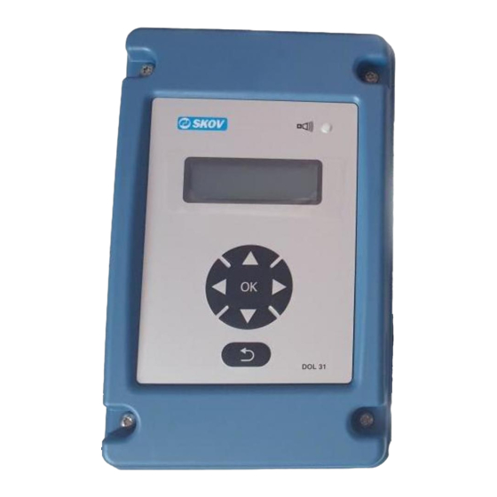
- Page 1 DOL 31 Speed Controller Technical User Guide 612061 • 2022-10-17...
- Page 2 The date of change appears from the front and back pages. Note • All rights belong to SKOV A/S. No part of this manual may be reproduced in any manner whatsoever without the expressed written permission of SKOV A/S in each case.
-
Page 3: Table Of Contents
Recommended tools........................ 8 Mounting of DOL 31 speed controller.................. 9 4 Installation guide............................ 10 Cabling............................ 10 Dismantling the AUT-0-MAN switch in DOL 31 16 A ............ 10 Connection in DOL 31 ...................... 11 Cable plans and circuit diagrams................... 12 4.4.1 General information about circuit diagrams ................ - Page 4 DOL 31 Speed Controller 7.9.1 Turn off............................ 23 7.9.2 Set turn off limit .......................... 24 7.10 Contrast ............................ 24 7.11 Backlight........................... 24 7.12 Language .......................... 24 7.13 Version Information ......................... 24 8 Settings ................................. 25 Factory settings ........................ 25 Functions in menu mode ...................... 25 Table relating to DOL 12 temperature sensor control............
-
Page 5: Product Description
• Manual control in which the DOL 31 output is set manually by means of the keyboard on the front. In addition, DOL 31 has an alarm relay (max. 24 V, 1A), and 1 control relay (max. 230 V, 12 A). The control re- lay could for instance be used for turning a heat or cooling source on and off. -
Page 6: Dol 31 Automatic - Slave Mode
DOL 31 Speed Controller 1.2 DOL 31 Automatic – Slave mode Controlled by a 0-10 V input signal. Controlled by a SKOV A/S controller Controlled by DOL 31 1.3 DOL 31 manual control Controlled manually with setting via the keyboard. Output can be set to 0 to 100 %. -
Page 7: Product Survey
DOL 31 Speed Controller 2 Product survey 130171 DOL 31 speed controller 6.8 A 0-10 V input or DOL 12 input (1) 0-10 V output (1) 60-230 V output (1) 24 V output (1) 24 V alarm relay (1) 230 V control relay (1) Supplied with: 1 DOL 12 temperature sensor, 3 plastic glands M25 and 3 plastic nuts M25. -
Page 8: Mounting Guide
DOL 31 Speed Controller 3 Mounting guide 3.1 Recommended tools Below follows a list of tools recommended for installation of the DOL 31. Item Description Cordless drill Drill kit Hammer Marker pen Multimeter Tape measure Side cutter Screwdriver Spirit level... -
Page 9: Mounting Of Dol 31 Speed Controller
DOL 31 Speed Controller 3.2 Mounting of DOL 31 speed controller 1. Remove the front panel and the flat cable plug (A). 2. Knock out the required number of knock-out pieces (B) at the bottom of the cabinet and mount the plastic glands. -
Page 10: Installation Guide
Cables are led through plastic glands in the bottom section. It is recommended to use armored cable in loca- tions where there is a risk of rodent attacks. 4.2 Dismantling the AUT-0-MAN switch in DOL 31 16 A Disconnect the supply voltage. -
Page 11: Connection In Dol 31
DOL 31 Speed Controller 4.3 Connection in DOL 31 Terminal block 0-10 V input signal from DOL 12; controller or another DOL 31. 0-10 V or 10-0 V output signal +24 V DC output Alarm relay NO Alarm relay COMMON... -
Page 12: Cable Plans And Circuit Diagrams
DOL 31 Speed Controller 4.4 Cable plans and circuit diagrams 4.4.1 General information about circuit diagrams Symbols are in accordance with the IEC/EN 60617 standard. The classification of the symbols ("letter codes") on the symbols is in accordance with the IEC/EN 81346-2 stan- dard. -
Page 13: Cable Plan Controller Dol 31
DOL 31 Speed Controller 4.4.5 Cable plan controller DOL 31 4.4.6 Circuit diagram controller to DOL 31 31 6.8 A = 10 A fuse 31 16 A = 16 A fuse DOL 31 Technical User Guide... -
Page 14: Cable Plan Dol 31 Master And Slave
DOL 31 Speed Controller 4.4.7 Cable plan DOL 31 Master and Slave 4.4.8 Circuit diagram DOL 31 Master and Slave DOL31 6.8 A = 10 A fuse 31 16 A = 16 A fuse DOL 31 Technical User Guide... -
Page 15: User Guide
High temperature alarm High supply frequency connected 5.3 Display Automatic Manual 5.4 AUT-0-MAN switch AUT (I) Auto (DOL 31 runs in the current user mode). Service mode (outputs are dead). MAN (II) 100 % (phase directly to output). Technical User Guide... -
Page 16: Keyboard
DOL 31 Speed Controller 5.5 Keyboard Up, down, right, left keys The arrow keys are used for navigation and changing of data and values. < 0.5 sec. By pressing you change the value by one either a menu or data. -
Page 17: Menu Mode
6 Menu mode Set DOL 31 to the required mode. (Automatic Master/Slave and Manual). 6.1 Automatic - Master mode It is controlled by a signal from the temperature sensor. DOL 31 automatically adjusts according to the set tem- perature. Set mode... -
Page 18: Manual Mode
Manual 6.3.1 Set output DOL 31 is manually controlled. Direct control of the output by pressing the up or down key. Output can be set to 0 to 100 %. Min. and max. output are left out of account. NOTE: Please note that certain fans require a minimum voltage. -
Page 19: Minimum Regulation Of Ac Output
DOL 31 Speed Controller 6.5 Minimum regulation of AC output Setting maximum power on output. The setting is made as a percentage of the supply voltage. Control of the output by pressing the up or down key. Min. setting (50 - 100 %) cannot be set higher than 50 %. -
Page 20: Service Menu
DOL 31 Speed Controller 7 Service menu Settings of service menus. Service menu 7.1 Active Alarms Displays the active alarms. Active Alarms 7.2 Set temperature alarm Temperature offset is set to activate alarm relay and alarm lamp. Alarm is released in case of high and low tem- perature. -
Page 21: Set Control Temperature
Negative offset value can be used for turning the heating system on/off. Positive offset value can be used for extra cooling. DOL 31 has a 0.5 °C hysteresis. This means that the control relay in the below example is deactivated again when the temperature increase to 12.5 °C. -
Page 22: Set Mininmum Analog Dc Output
7.7 Selecting temperature scale Select whether the temperature scale indication should be in Celsius or Fahrenheit. Selecting temperature scale Celsius 7.8 Invert When using DOL 31 for heating or recirculation, the output can be inverted. Invert Not inverted Inverted Technical User Guide... -
Page 23: Turn Off Functions
1. Safety mode ensures that the DOL 31 output is set to 50 % if the analog input signal gets lower than 0.5 V. 2. Turn off limit: If safety mode is not selected, it is possible to select a turn off limit. When this function is cho- sen, the DOL 31 output will be switched off if the analogue input signal is lower than this turn off limit. -
Page 24: Set Turn Off Limit
The function is applied if there is a requirement for the DOL 31 output to be cut off completely at a certain volt- age on the analog control signal (turn off limit). If the turn off limit is set to 0 V, the function is inactive and the DOL 31 output will remain at minimum (not in- verted) or maximum (inverted). -
Page 25: Settings
DOL 31 Speed Controller 8 Settings 8.1 Factory settings DOL 31 has following default setup. Menu item Minimum Default settings Maximum Daily User Menu 0 °C 20 °C 40 °C Temperature Automatic - Slave Mode 0 VRMS = 0 %... - Page 26 DOL 31 Speed Controller 8.3 Table relating to DOL 12 temperature sensor control °C kΩ* °C kΩ* °C kΩ* 82.50 8.08 20.71 5.29 10.72 3.73 76.84 7.96 20.09 5.22 10.45 3.67 70.60 7.83 19.48 5.15 10.19 3.61 63.97 7.68 18.90 5.07...
-
Page 27: Replacing Triac
DOL 31 Speed Controller 9 Replacing Triac When the DOL 31 is used for light control with incandescent bulbs, the bulbs can short-circuit when failing, causing the triac to break. 1. Order 130828 DOL 31 - 5 pcs. all-purpose triac, consisting of 5 individual triacs in a bag. -
Page 28: Maintenance
DOL 31 Speed Controller 10 Maintenance 10.1 Cleaning Clean the product with a cloth that has been wrung out almost dry in water and avoid using: • high-pressure cleaner • solvents • corrosive/caustic agents 10.2 Recycling/Disposal Products suitable for recycling are marked with a pictogram. -
Page 29: Trouble Shooting Instructions
DOL 31 Speed Controller 11 Trouble shooting instructions Error Error correction No light in the display. Check the supply voltage, fuses, residual current cir- cuit breaker. The fan is not running Check that the AUT-0-MAN switch is set on the re-... -
Page 30: Technical Data
DOL 31 Speed Controller 12 Technical data Electrical V AC 110/230 ±10% Rated voltage 50/60 Frequency 6.8 A version: 700/1500 Motor load max. 16 A version 1700/3600 Motor load, min. 0-10 V or DOL 12 Input Analog 0-10 V 24 V 100 mA... - Page 32 SKOV A/S • Hedelund 4 • Glyngøre • DK-7870 Roslev Tel. +45 72 17 55 55 • www.skov.com • E-mail: skov@skov.dk...
Need help?
Do you have a question about the DOL 31 and is the answer not in the manual?
Questions and answers