Table of Contents
Advertisement
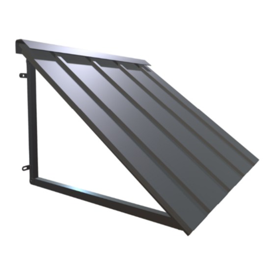
HOUSTONIAN STANDING SEAM METAL AWNING
OWNER'S MANUAL & INSTALLATION INSTRUCTIONS
Contents
ATTENTION: Warning Statement ............................................................................................. 2
Hardware for different surface applications ........................................................................... 2
Measuring Guide ....................................................................................................................... 2
Parts List (Mounting Hardware not included) ............................................................................... 4
Assembly for 3ft and 4ft Wide Houstonian Awnings .................................................................... 6
Step 1: Ensure all parts are included ..................................................................................... 6
Step 2: Frame Assembly for 3ft & 4ft Houstonians: ................................................................ 7
Step 3: Insert the Spines onto the Front Bar and Top Bar ....................................................... 8
Step 4: Laying out the Right, Middle, and Left Panels onto the Assembled Frame .................. 9
Step 5: Input the Sheet Screws for the Panels ...................................................................... 10
Step 6: Attaching the Back Bars to the Top Bar .................................................................... 12
Step 7: Attaching the Projection Bars to the Back Bars ......................................................... 13
Step 8: Installing the Shroud (Hood Cover) to the Surface .................................................... 14
Step 9: Assembling the (p) Top Bar Bracket onto the Inside of the (c) Top Bar ..................... 16
Step 10: Mounting the Back Bars of the Assembled Awning to the Surface .......................... 17
Step 11: Mount the (p) Top Bar Bracket to the surface ......................................................... 18
Step 12: Your Houstonian is complete! ................................................................................. 19
WARRANTY ............................................................................................................................. 20
3' & 4' Sizes (Exact width 44" & 56")
Advertisement
Table of Contents

Subscribe to Our Youtube Channel
Related Manuals for Awntech Houstonian


Summary of Contents for Awntech Houstonian
-
Page 1: Table Of Contents
Measuring Guide ........................2 Parts List (Mounting Hardware not included) ................4 Assembly for 3ft and 4ft Wide Houstonian Awnings ..............6 Step 1: Ensure all parts are included ..................6 Step 2: Frame Assembly for 3ft & 4ft Houstonians: ..............7 Step 3: Insert the Spines onto the Front Bar and Top Bar ............ -
Page 2: Attention: Warning Statement
Please refer to the below measuring guide for our Houstonian model awning. The image shown below represents the back of the Houstonian frame, or the part of the frame that is in contact with the mounting surface. It should be noted that the back frame of our Houstonian model awning varies only in width between our standard sizes. - Page 3 TABLE 1 SIZE TOTAL (in) INSIDE (in) 34.25 46.25 58.25 70.25 82.25 94.25 IF YOU ROTATE THE MOUNTING BARS 180 DEGREES CLOCKWISE, THE INSIDE DIMENSIONS ARE AS FOLLOWS: TABLE 2 SIZE TOTAL (in) INSIDE (in) Page | 3...
-
Page 4: Parts List (Mounting Hardware Not Included)
Parts List (Mounting Hardware not included) NOTE: A bottle of touch up paint is included with each awning for your convenience. After assembly, please inspect your awning for scratches or exposed metal. If you notice exposed metal, liberally apply touchup paint to the afflicted areas. Please note that the touchup paint not only conceals the damages, but also protects the metal from corrosion or rust. - Page 5 Right Back Bar Left Projection Bar Right Projection Bar Bolt for Projection and Back Bars Nut for Projection and Back Bars Full Shroud (Hood Cover) Top Bar Bracket Page | 5...
-
Page 6: Assembly For 3Ft And 4Ft Wide Houstonian Awnings
Assembly for 3ft and 4ft Wide Houstonian Awnings For video assistance on Houstonian assembly, please navigate to our YouTube page at: https://youtu.be/G44LiwmYEGY Note that the mounting tabs in the images below can be reversed/installed for interior- frame mounting. Please refer to our Measuring Guide herein. -
Page 7: Step 2: Frame Assembly For 3Ft & 4Ft Houstonians
Frame Assembly for 3ft & 4ft Houstonians: Step 2: Parts Required (3’ & 4’) 4-(a) Black Nylon “L” Connectors 1-(b) Front Bar 1-(c) Top Bar (with hook extenders) 1-(d1) Left Frame 1-(d2) Right Frame 1 Rubber Mallet/Hammer Lay out the frame parts to where the (d1) Left Frame and (d2) Right Frame are parallel to one another, and the (b) Front Bar is parallel to the (c) Top Bar (with hooks). -
Page 8: Step 3: Insert The Spines Onto The Front Bar And Top Bar
Using a drill and (f) Sheet Screws, connect the ends of each (e) Spine to the pre-drilled holes on the (b) Front Bar and the (c) Top Bar (with hook extenders). Refer to the figure below. Figure B1: Inserting Spines for a Houstonian 4ft Example Page | 8... -
Page 9: Step 4: Laying Out The Right, Middle, And Left Panels Onto The Assembled Frame
Right Panel is the side/lip hanging down over the (d2) Right Side Frame. This will cover the right side of the awning frame when the (b) Front Bar is closest to you. Figure C1: Layout of Panels for Houstonian 4ft Example Page | 9... -
Page 10: Step 5: Input The Sheet Screws For The Panels
Input the Sheet Screws for the Panels Step 5: Parts Required (3’) Parts Required (4’) 14-(f) Sheet Screws 16-(f) Sheet Screws Drill Drill 5a) Now that the panels are in place, you will need to insert the (f) Sheet Screws on the outside perimeter of the frame. - Page 11 Figure D2: Input (f) Sheet Screws into the (c) Top Bar Figure D3: Input Sheet Screws into the Left Frame and Right Frame Page | 11...
-
Page 12: Step 6: Attaching The Back Bars To The Top Bar
Attaching the Back Bars to the Top Bar Step 6: Parts Required (3’ & 4’) 1-(j1) Left Back Bar 1-(j2) Right Back Bar 2-(l) Bolts 2-(m) Nuts 6a) Install the (j1) Left Back Bar and (j2) Right Back Bar into their respective hinges on the (c) Top Bar with Hook Extenders. -
Page 13: Step 7: Attaching The Projection Bars To The Back Bars
Attaching the Projection Bars to the Back Bars Step 7: Parts Required (3’ & 4’) 1-(k1) Left Projection Bar 1-(k2) Right Projection Bar 4-(l) Bolts 4-(m) Nuts 7a) Install the (k1) Left Projection Bar and (k2) Right Projection Bar into their respective hinges on the (j1 / j2) Back Bars and (b) Front Bar. -
Page 14: Step 8: Installing The Shroud (Hood Cover) To The Surface
Installing the Shroud (Hood Cover) to the Surface Step 8: Parts Required (3’ & 4’) Mounting Hardware (Consult a Professional) 1-(n) Shroud (Hood Cover) Drill Level Measuring Tape 8a) Carefully measure the distance between each pre-drilled hole on the (n) Shroud (Hood Cover) with measuring tape. - Page 15 Figure G2: Installing (n) Shroud (Hood Cover) to the prepared Pilot Holes Page | 15...
-
Page 16: Step 9: Assembling The (P) Top Bar Bracket Onto The Inside Of The (C) Top Bar
Step 9: Assembling the (p) Top Bar Bracket onto the Inside of the (c) Top Bar Parts Required (3’ & 4’) 2-(f) Sheet Screws Drill 9a) Align the (p) Top Bar Bracket with the (c) Top Bar with Hook Extenders by matching the pre-drilled holes on both pieces. -
Page 17: Step 10: Mounting The Back Bars Of The Assembled Awning To The Surface
Mounting the Back Bars of the Assembled Awning to the Surface Step 10: Parts Required (3’ & 4’) Mounting Hardware (Consult a Professional) Drill 10a) Using the mounting tabs of the (j1) Left Back Bar and the (j2) Right Back Bar as a reference, mark the location on the mounting surface using chalk/graphite noting the location of the holes to be drilled. -
Page 18: Step 11: Mount The (P) Top Bar Bracket To The Surface
Step 11: Mount the (p) Top Bar Bracket to the surface Parts Required (3’ & 4’) Mounting Hardware (Consult a Professional) Drill 11a) Using the (p) Top Bar Bracket as a guide for placement of the (o) M8 or M6 Anchors, follow similar procedures in Step 8 and Step 10 to prepare (o) M8 or M6 Anchors in the mounting surface. -
Page 19: Step 12: Your Houstonian Is Complete
Your Houstonian is complete! Step 12: Page | 19... -
Page 20: Warranty
D. WHAT ARE THE RESPONSIBILITIES OF AWNTECH UNDER THIS WARRANTY? Subject to the terms and conditions set forth herein, Awntech Corporation will furnish replacements for parts found by Awntech Corporation to be defective in design, manufacture or assembly, under each specific component or product warranty as set forth below. - Page 21 Freight expenses to and from Awntech Corporation are not covered by this Warranty and must be paid by • the purchaser. A bottle of touch up paint is included with each awning. It is the responsibility of the purchaser to inspect •...
Need help?
Do you have a question about the Houstonian and is the answer not in the manual?
Questions and answers
Overall dim. of wdo is 60.75 in wide by 48.50 in vertical, i.e. it is also the size of the opng in the wall which accommodates the window. What is Awntech's [Hustonian awning model] recommended size for this window whose anchor mounting locations fit the window framing?? The typical wall is 2 by 4 wood studs, wall sheathing, and stuccoed. The concern is ordering an awning, like the Hustonian, whose mounting points find the wood studs.