Table of Contents
Advertisement
Quick Links
Advertisement
Table of Contents

Related Manuals for Waterous HLU Series


Summary of Contents for Waterous HLU Series
- Page 1 Form Number: F-2868 Issue Date: Jan 30, 2020 Revision Date: Nov 30, 2022 HLU Series Fire Pump Installation, Operation, and Maintenance Waterous Company • 125 Hardman Avenue South • South Saint Paul, MN 55075 • (651) 450-5000 www.waterousco.com...
-
Page 3: Table Of Contents
Maintenance Schedule Symbols Cleaning the Intake Strainer Product Overview Checking the Pedestal Oil Level Draining the Pedestal Oil HLU Series Pump Overview and Versions Adding the Pedestal Oil HLU Pump Operation Overview Pump Components—Intake Side Pressure Mode Controller—Optional Pressure Mode Switch Pump Components—Underside... -
Page 4: Safety
• Read and understand all the notices and safety precautions. • Be aware that these instructions are only guidelines and are not meant to be definitive. Contact Waterous when you have questions about installing, Before Operation operating, or maintaining the equipment. - Page 5 Safety Introduction Product Overview Installation Operation Maintenance NOTICE Premature Failure High Pressure •Premature component Liquid ejected at high • failure occurs when pressure can cause operating beyond serious injury. system specifications. Drain the pump after use • •Do not operate the system and before servicing.
- Page 6 Safety Introduction Product Overview Installation Operation Maintenance Moving Parts High Pressure Rotating parts can cause Liquid ejected at high • • severe injury or death pressure can cause serious injury. Keep clear of moving • parts when the equipment Purge all pressure before •...
-
Page 7: Introduction
Operation Maintenance Using this Document Use this document to install and operate your Waterous equipment. Understand the following conditions before continuing with the document: Use the guidelines below when viewing this document. • The instructions may refer to options or equipment that you may not have Viewing the Document Electronically purchased with your system. -
Page 8: Hlu Series Pump Overview And Versions
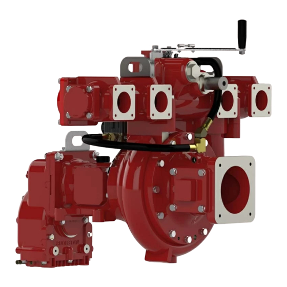
HLU Series Pump Overview and Versions The HLU series pump has a discharge manifold with 8 normal pressure discharges and 1 high-pressure discharge. A lever on the pump opens a crossover valve that diverts a portion of the incoming water into the high-pressure discharge, while simultaneously operating the remaining discharges. The pump is available in several variations. -
Page 9: Hlu Pump Operation Overview
Safety Introduction Product Overview Installation Operation Maintenance HLU Pump Operation Overview You can operate the pump in 3 modes: high pressure, low pressure, and simultaneous mode. Each mode is achieved by opening or closing a combination discharges. Access low pressure mode by closing the crossover valve and opening the low pressure discharges. Access high pressure mode by opening the crossover valve and closing the low pressure discharges. -
Page 10: Pump Components-Intake Side
Safety Introduction Product Overview Installation Operation Maintenance Pump Components—Intake Side... - Page 11 Safety Introduction Product Overview Installation Operation Maintenance Fire Pump Components—Intake Side Feature Feature Description Description Crossover valve handle This opens and closes the crossover valve that diverts a portion of the incoming water into the high-pressure discharge. Low-pressure discharge The low pressure discharge offers 6 outlets for 65 mm adapters and 2 outlets for 80 mm adapters. You can install a blind manifold flange or 1 to 3-inch tapped flanges to the outlets.
-
Page 12: Pressure Mode Controller-Optional
Safety Introduction Product Overview Installation Operation Maintenance Pressure Mode Controller—Optional The pressure mode controller allows you to remotely actuate the crossover valve. The pressure mode controller is available as a factory installed option. - Page 13 Safety Introduction Product Overview Installation Operation Maintenance Pressure Mode Controller—Optional Feature Feature Description Description Bracket This mounts the controller to the pump. Cylinder This controls the actuation speed of the cylinder. Flow control This controls the cylinder movement. Controller This houses the electronics and manages operation. Actuator switch connector This connects to the pressure mode switch—DT04-6P.
-
Page 14: Pressure Mode Switch
Safety Introduction Product Overview Installation Operation Maintenance Pressure Mode Switch... - Page 15 Safety Introduction Product Overview Installation Operation Maintenance Pressure Mode Switch Feature Feature Description Description Mounting holes This mounts the switch to the apparatus. Mode switch This operates the pressure mode controller. Connector This connects to the pressure mode controller—DT06-6S.
-
Page 16: Pump Components-Underside
Safety Introduction Product Overview Installation Operation Maintenance Pump Components—Underside... - Page 17 Safety Introduction Product Overview Installation Operation Maintenance Pump Components—Underside Feature Feature Description Description Tachometer This measures the impeller shaft rotational speed—4 pulses per revolution. Pedestal This mounts the pump to the apparatus. Pedestal drain plug This drains the oil from the pedestal. Pump drain plug This drains the water from the pump.
-
Page 18: Pump Components-Drive Side With Direct Drive
Safety Introduction Product Overview Installation Operation Maintenance Pump Components—Drive Side with Direct Drive... - Page 19 Alternatively, you can choose to substitute the external pressure-relief valve with one with the same specifications as the valve supplied by Waterous, or employ a speed-governor system that limits the pump speed to 3450 rpm when the high-pressure discharge is enabled.
-
Page 20: Pump Components-Drive Side With K-Transmission
Safety Introduction Product Overview Installation Operation Maintenance Pump Components—Drive Side with K-Transmission... - Page 21 Alternatively, you can choose to substitute the external pressure-relief valve with one with the same specifications as the valve supplied by Waterous, or employ a speed-governor system that limits the pump speed to 3450 rpm when the high-pressure discharge is enabled.
-
Page 22: Pump Components-Drive Side With Pa-Transmission
Safety Introduction Product Overview Installation Operation Maintenance Pump Components—Drive Side with PA-Transmission... - Page 23 Alternatively, you can choose to substitute the external pressure-relief valve with one with the same specifications as the valve supplied by Waterous, or employ a speed-governor system that limits the pump speed to 3450 rpm when the high-pressure discharge is enabled.
-
Page 24: Operating Limits
Safety Introduction Product Overview Installation Operation Maintenance Operating Limits Every application has operating limits. Do not exceed the maximum pressure or Operating the pump beyond recommended maximum pressure can causes speed listed below during operation. liquid to eject at high pressure—this can cause injury to the operator and/or bystanders. -
Page 25: Installation
This equipment is intended to be installed by a person or persons with the basic This equipment is intended to operate as designed. Do not remove, modify, or knowledge of installing similar equipment. Contact Waterous with questions change the components in the system. Doing so will void the warranty. -
Page 26: Mounting Holes And Flange Cutout
Safety Introduction Product Overview Installation Operation Maintenance Mounting Holes and Flange Cutout Use the illustration to locate and drill the pedestal mounting holes, the pump flange cutout, and drain-plug hole. 10.500in 266.700mm 1.875in 1.000in 47.625mm 25.400mm 6.000in 152.400mm 4X 0.781in 1.57in 19.837mm 39.878mm... -
Page 27: Installing The Pump-Hlud
Safety Introduction Product Overview Installation Operation Maintenance Installing the Pump—HLUD Use the illustration and instructions to install the pump. Locate the pump where you can access the mode handle, and perform regular maintenance. The pump location must comply with the drive-shaft requirements. -
Page 28: Installing The Pump-Hluk
Safety Introduction Product Overview Installation Operation Maintenance Installing the Pump—HLUK Use the illustration and instructions to install the pump. Locate the pump where you can access the crossover valve handle and perform regular maintenance. The pump location must comply with the drive-shaft requirements. -
Page 29: Installing The Pump-Hlupa
Safety Introduction Product Overview Installation Operation Maintenance Installing the Pump—HLUPA Use the illustration and instructions to install the pump. Locate the pump where you can access the crossover valve handle and perform regular maintenance. The pump location must comply with the drive-shaft requirements. -
Page 30: Installing The Pump Drain Lines-Pump Body
Safety Introduction Product Overview Installation Operation Maintenance Installing the Pump Drain Lines—Pump Body Use the illustration and instructions to install the pump drain line. All freezable fluids must be drained from the pump to prevent damage. NOTICE Freeze Damage Do not allow fluid in the •... -
Page 31: Installing The Transmission Drain Lines-K Transmission
Safety Introduction Product Overview Installation Operation Maintenance Installing the Transmission Drain Lines—K Transmission Use the illustration and instructions to install the transmission drain lines. All freezable fluids must be drained from the transmission to prevent damage. Note: Multiple options are available for draining the oil cooler on the K-transmission. -
Page 32: Installing The Transmission Drain Lines-Pa Transmission
Safety Introduction Product Overview Installation Operation Maintenance Installing the Transmission Drain Lines—PA Transmission Use the illustration and instructions to install the transmission drain lines. All freezable fluids must be drained from the transmission to prevent damage. NOTICE Freeze Damage Do not allow fluid in the •... -
Page 33: Connecting The Pump
Safety Introduction Product Overview Installation Operation Maintenance Connecting the Pump Use the illustration and instructions to connect the various pump components to the apparatus. 1 Connect the pump intake to a water source. 2 Connect the appropriate outlets on the low-pressure discharge manifold to the discharges on the apparatus. -
Page 34: Connecting The Pneumatic Actuator
Safety Introduction Product Overview Installation Operation Maintenance Connecting the Pneumatic Actuator Use the illustration and instructions to connect the various pump components to the apparatus. 1 If applicable to your application, connect the CANbus connector to the CANbus controller. 2 Connect the solenoid valve to the compressed air supply. -
Page 35: Mode Switch Extension Cable
Safety Introduction Product Overview Installation Operation Maintenance Mode Switch Extension Cable Your application may require an extension cable to connect between the mode switch and the controller. Use locally sourced components and the information below to construct an extension cable for your application. Deutsch Connector Deutsch Connector Deutsch Connector... -
Page 36: Setting The Canbus Terminating Resistor
Safety Introduction Product Overview Installation Operation Maintenance Setting the CANbus Terminating Resistor Use the illustration and instructions to set the CANbus terminating resistor if your application uses CANbus communication. 1 Remove and set aside the vent plug. Install the vent plug after setting the dip switches. 2 Set the terminating resistor dip switches to the following: •... -
Page 37: Adjusting The Flow Controls
Safety Introduction Product Overview Installation Operation Maintenance Adjusting the Flow Controls Use the illustration and instructions to adjust the flow controls on the cylinder. 1 Adjust this flow control valves to cause the cylinder to fully extend, or retract between 3 and 5 seconds. -
Page 38: Operation
Safety Introduction Product Overview Installation Operation Maintenance Enabling the High-Pressure Discharge—Manual Handle Use the illustrations and instructions to enable the high-pressure discharge. Note: Make sure that you set the engine to idle before you engage the high-pressure discharge to avoid activating the external pressure relief valve or the speed governor system. -
Page 39: Enabling The High-Pressure Discharge-Pressure Mode Controller
Safety Introduction Product Overview Installation Operation Maintenance Enabling the High-Pressure Discharge—Pressure Mode Controller Use the illustrations and instructions to enable the high-pressure discharge. Note: Make sure that you set the engine to idle before you engage the high-pressure discharge to avoid activating the external pressure relief valve or the speed governor system. -
Page 40: Operating The Manual Override Mode
Safety Introduction Product Overview Installation Operation Maintenance Operating the Manual Override Mode Use the illustrations and instructions to operate manual override. 1 On startup, the cylinder is in the low-pressure mode. This is the default state for the system. 2 When switching to high-pressure mode, the solenoid valve retracts the cylinder to open the crossover valve, making the high pressure discharge available. -
Page 41: Maintenance
Safety Introduction Product Overview Installation Operation Maintenance Maintenance Schedule Perform the following procedures at the recommended intervals at a minimum. Environmental conditions determine the maintenance intervals. Inspect the components frequently and create a maintenance schedule suitable to your application and environmental conditions. Replace wear components with equivalent components. -
Page 42: Cleaning The Intake Strainer
Safety Introduction Product Overview Installation Operation Maintenance Cleaning the Intake Strainer Use the illustrations and instructions to clean the intake strainer. Note: Make sure that you purge all pressure before continuing. High Pressure Liquid ejected at high • pressure can cause serious injury. -
Page 43: Checking The Pedestal Oil Level
Safety Introduction Product Overview Installation Operation Maintenance Checking the Pedestal Oil Level Use the illustrations and instructions to check the pedestal-oil level. 1 To check the pedestal-oil level do the following: • Unscrew the oil-fill cap. • Wipe the dipstick clean. •... -
Page 44: Draining The Pedestal Oil
Safety Introduction Product Overview Installation Operation Maintenance Draining the Pedestal Oil Use the illustrations and instructions to drain the pedestal oil. 1 Perform the following to drain the pedestal oil: • Place a suitable container under the pedestal to collect the oil. •... -
Page 45: Adding The Pedestal Oil
Safety Introduction Product Overview Installation Operation Maintenance Adding the Pedestal Oil Use the illustrations and instructions to add the pedestal oil. Use 1 qt (0.95 L), SAE 10W-30, standard or synthetic. 1 Remove the oil-fill cap from the pedestal. 2 Add oil to the pedestal. 3 Check the oil level. - Page 46 Waterous Company 125 Hardman Avenue South South Saint Paul, MN 55075 (651) 450-5000 www.waterousco.com...
Need help?
Do you have a question about the HLU Series and is the answer not in the manual?
Questions and answers