Table of Contents
Advertisement
Quick Links
Read through the installation
instructions carefully before
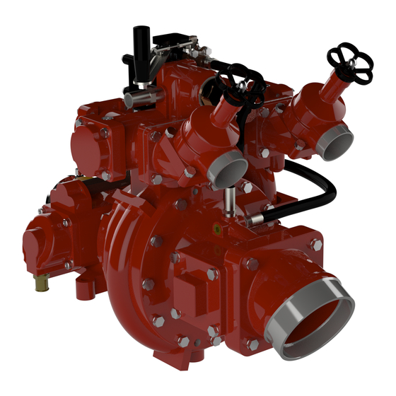
installing your Waterous HL
Series Fire Pump.
NOTE: Instructions subject to change without notice
Waterous Company, 125 Hardman Avenue South, South St. Paul, Minnesota 55075 USA (651) 450-5000
HL Series Centrifugal Fire Pumps
Introduction . . . . . . . . . . . . . . . . . . . . . . . . . . . . . . . . . . . . . . . . . . . . . . . . . . . 2
General Description . . . . . . . . . . . . . . . . . . . . . . . . . . . . . . . . . . . . . . . . . . . . 2
Operational Limits .................................................................................... 2
Available Pump Models ........................................................................... 2
Installation Instructions ........................................................................... 3
Pump Lifting Points ................................................................................ 3
Pump Mounting ...................................................................................... 4
Pump Intake . . . . . . . . . . . . . . . . . . . . . . . . . . . . . . . . . . . . . . . . . . . . . . . . . 5
Low Pressure Discharge ........................................................................ 5
High Pressure Discharge ....................................................................... 5
High Pressure Inlet Strainer . . . . . . . . . . . . . . . . . . . . . . . . . . . . . . . . . . . . 5
High Pressure Relief Valve .................................................................... 5
Thermal Relief Valve . . . . . . . . . . . . . . . . . . . . . . . . . . . . . . . . . . . . . . . . . . 5
Piston Primers ....................................................................................... 6
Lubrication ............................................................................................. 7
Pedestal (Primer Housing) Fill and Drain ........................................... 7
K Series Transmission Fill and Drain . . . . . . . . . . . . . . . . . . . . . . . . . . 7
Pump Water Drains . . . . . . . . . . . . . . . . . . . . . . . . . . . . . . . . . . . . . . . . . . . 9
Tachometer Connection . . . . . . . . . . . . . . . . . . . . . . . . . . . . . . . . . . . . . . . 9
Optional Items ...................................................................................... 10
Solenoid Valve for PIV (Priming Isolation Valve) . . . . . . . . . . . . . . . 10
RTP Foam Systems: ....................................................................... 11
Installed on Pump at Factory ....................................................... 11
Mounted Remotely from Pump .................................................... 11
Control Panel . . . . . . . . . . . . . . . . . . . . . . . . . . . . . . . . . . . . . . . . . . . . . 12
Final Checks ........................................................................................... 13
Lubrication ........................................................................................... 13
Testing . . . . . . . . . . . . . . . . . . . . . . . . . . . . . . . . . . . . . . . . . . . . . . . . . . . . . 13
www.waterousco.com
Installation Instructions
Table of Contents
F-1031, Section 3032 (Rev: 6/7/19)
Advertisement
Table of Contents

Related Manuals for Waterous HL Series


Summary of Contents for Waterous HL Series
-
Page 1: Table Of Contents
Testing ........... . . 13 F-1031, Section 3032 (Rev: 6/7/19) Waterous Company, 125 Hardman Avenue South, South St. Paul, Minnesota 55075 USA (651) 450-5000 www.waterousco.com... -
Page 2: Introduction
Introduction This instruction covers the typical installation of any HL Series pump regardless of the model or intake and discharge. General Description The HL series are pedestal mounted fire pumps designed to operate in to modes: Low Pressure Mode Three performance levels are available: Pump only low pressure water. -
Page 3: Installation Instructions
Installation Pump Lifting Points Direct Drive Models HL200D, HL300D, HL400D Gear Drive Models HL200K, HL300K, HL400K Page 3 of 13 F−1031, Section 3032... -
Page 4: Pump Mounting
(plate line shaft length and angles are in accordance with the drive- not supplied by Waterous). The mounting plate should be line manufacturer's specification. designed with the four mounting holes (see diagram below Connect the driveline to the companion flange provided on for dimensions). -
Page 5: Pump Intake
Pump Intake High Pressure Inlet Strainer If piping is to be attached to the pump intake, provisions must Pump installation should provide access as this is a main- be made to allow the removal of the pump intake adapter tenance item. while the pump remains in the vehicle. -
Page 6: Piston Primers
Piston Primers Clearance for Service Primer Discharge The pump has (2) two automatic piston primers located on During operation, the primers can discharge water. This wa- each side of the pump pedestal. Pump installation must ter exits through the primer discharge outlets. It is important provide 50 mm (2 in.) of space behind the primers to allow that this water is not restricted in any way. -
Page 7: Lubrication
Lubrication NOTICE Pump installation must provide for access to the lubrication fills and drains. Models HL200 and HL300D Pedestal (Primer Housing) Fill and Drain - HL200D, HL300D Models HL200K, HL300K, HL300D, HL400D Pedestal (Primer Housing) and K Series Transmission Fill and Drain See next page for K Series Transmission requirements. - Page 8 Lubrication NOTICE Pump installation must provide for access to the lubrication fills and drains. Models HL200K, HL300K and HL400K Only Transmission Mounted Vertically Page 8 of 13 F−1031, Section 3032...
-
Page 9: Pump Water Drains
Pump Water Drains The pump is provided with a 3/4 NPT water drain. The drain NOTICE should be fitted with piping, valve and routed to suitable draining location. All piping, fittings and valves must be suitable for pres- sures that are present in the low and high pressure stages. -
Page 10: Solenoid Valve For Piv (Priming Isolation Valve)
Solenoid Valve for PIV (Priming Isolation Valve) TO PTO ACTUATOR AIR INLET CONNECTOR ON PUMP PRIMING ISOLATION VALVE IPIVI. PTO SWITCH CONNECT 6mm TUBING TO 6mm TUBING PUSH-ON FITTING 16 OR 18 AWG WIRE PRIMING VAL VE SOLENOID, REMOTELY MOUNT IN CHASSIS ISEE DIMENSION AND WIRING DETAILS! FROM CHASSIS AIR SUPPLY... -
Page 11: Rtp Foam Systems
RTP Foam System (RTP Foam System is Optional) Installed on Pump at Factory: Install the Foam Suction Hose: Install the barbed fitting in the tap located on the bottom of the Proportioner Valve. Attach the hose and wand to the barbed fitting using the clamps provided. -
Page 12: Control Panel
Control Panel (Control Panel is Optional) Complete Electrical Connections for the fol- Complete Electrical Connections and Tank lowing: Connections for the following: • Tachometer / Hourmeter • Optional Tank Level Monitors • Pump Overheat Module • Pump Engaged Module Control Panel Page 12 of 13 F−1031, Section 3032... -
Page 13: Final Checks
(mounting, driveline, piping, etc.) are se- operation, listen for unusual noises and check for leaks. cure. To run the pump, follow instructions F-1031, Section 2408, HL Series Fire Pump Operation and Maintenance Instruc- tions. Page 13 of 13 F−1031, Section 3032...
Need help?
Do you have a question about the HL Series and is the answer not in the manual?
Questions and answers