Table of Contents
Advertisement
and overhaul instructions carefully
before repairing your Waterous HL
Series Fire Pump.
NOTE: Instructions subject to change without notice
Waterous Company, 125 Hardman Avenue South, South St. Paul, Minnesota 55075 USA (651) 450-5000
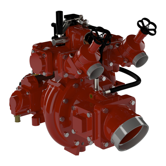
HL Series Centrifugal Fire Pumps
Introduction
Pump Models
K Series Transmission Overhaul
www.waterousco.com
Overhaul Instructions
Table of Contents
. . . . . . . . . . . . . . . . . . . . . . . . . . . . . . . . . . . . . . . . . . . . . . . . . . .
. . . . . . . . . . . . . . . . . . . . . . . . . . . . . . . . . . . . . . . . . . . . . . . . . .
. . . . . . . . . . . . . . . . . . . . . . . . . . . . . . . . . . . . . . . . . . . . . .
. . . . . . . . . . . . . . . . . . . . . . . . . . . . . . . . . . . . . . . . . .
. . . . . . . . . . . . . . . . . . . . . . . . . . . . . . . . . . .
. . . . . . . . . . . . . . . . . . . . . . . . . . . . . . . . . . . . . . . . . . . . .
. . . . . . . . . . . . . . . . . . . . . . . . . . . . . . . . . . . . . . . . . . . . .
. . . . . . . . . . . . . . . . . . . . . . . . . . . . . . . . . . . . . . . . . . . . . .
. . . . . . . . .
See F-1031, Section 4309
F-1031, Section 4321 (Rev: 6/7/19)
2
2
3
4
5
6
7
8
Advertisement
Table of Contents

Related Manuals for Waterous HL Series


Summary of Contents for Waterous HL Series
-
Page 1: Table Of Contents
Read through the safety information and overhaul instructions carefully before repairing your Waterous HL Series Fire Pump. NOTE: Instructions subject to change without notice F-1031, Section 4321 (Rev: 6/7/19) Waterous Company, 125 Hardman Avenue South, South St. Paul, Minnesota 55075 USA (651) 450-5000 www.waterousco.com... - Page 2 Introduction This instruction provides the necessary steps to overhaul HL Series Fire Pumps. Note that the instructions are divided into Disassembly and Reassembly sections, see Pages 7 and 8 for indexes. HL200K, HL300K and HL400K Gear Drive Models Only: This instruction covers the removal of the K Series Transmission from the pump only. For transmission overhaul instructions, see separate instructions F-1031, Section 4309.
-
Page 3: Read Through The Safety Information
Safety Information Read through the safety information carefully prior to working on your Waterous Fire Pump. WARNING WARNING Death or serious personal injury might occur if proper operating procedures Scalding Water Hazard. May result in serious burns. are not followed. The pump operator, as well as individuals connecting... -
Page 4: Ordering Repair Parts
Ordering Repair Parts When ordering repairs parts, furnish the reference number of the component Refer to the Service Parts Lists furnished with your pump for identification of indi (from Service Parts List) along with the Pump Model and the Serial Number. vidual components. -
Page 5: General Overhaul Information
Installing Ball Bearings Before disassembling a pump, test it thoroughly, if possible, and record the Most Waterous pumps are designed so that ball bearings fit tightly on their results. A comparison of this test with periodic tests recommended in form shafts and have relatively loose fits in the bearing housings. -
Page 6: Pump Components
Pump Components Direct Drive Model HL300D Shown NOTE: For clarity, diagram does not show fittings installed on the pump intake and discharge openings. Location of some components vary slightly based on pump model and input rotation. Page 6 of 57 F−1031, Section 4321... -
Page 7: Disassembly Index
Disassembly Index Remove Pump from Vehicle: Remove Primers: Drain Lubrication from Pump ........Pumps with PIV (Priming Isolation Valve) . -
Page 8: Reassembly Index
Reassembly Index Inspection and Repair: ......... . Install Discharge: Assemble Impeller Shaft Determining Impeller Rotation... -
Page 9: Remove Pump From Vehicle: Drain Lubrication From Pump
Disassembly - Remove Pump from Vehicle Drain Lubricants from Pump Models HL200D, HL300D and HL400D 1. Drain lubricant from Pedestal (Primer Housing). Models HL200D and HL300D Model HL400D Models HL200K, HL300K and HL400K Drain lubricant from Pedestal (Primer Housing) and K Series Transmission Transmission Mounted to the Left Transmission Mounted Vertically Pedestal (Primer Housing) -
Page 10: Disconnect Piv (Priming Isolation Valve) Air Line
Disconnect PIV (Priming Isolation Valve) Air Line 1. Required only if your pump is equipped with optional PIV feature. 2. Connection made with push-on fitting. 3. Push in fitting retaining ring and hold. Firmly grasp air line and pull out of fitting. Page 10 of 57 F−1031, Section 4321... -
Page 11: Remove Pump
Remove Pump 1. Disconnect driveline, intake piping, discharge piping, pump and primer drain lines, tachometer cable and any accessory equipment connections. 2. Remove four bolts attaching the pump to the vehicle frame. 3. Lift the pump out of the vehicle using the lifting points on the pump. Models HL200D, HL300D and HL400D Models HL200K, HL300K and HL400K Page 11 of 57... -
Page 12: Disconnect Hoses
Disassembly - Remove Intake Fitting Disconnect Hoses 1. Disconnect all hoses attached to the intake fitting. NOTE: If the hose connection at the intake fitting is not a swivel connection, disconnect hose at other end. Disconnect all hoses attached at these points. -
Page 13: Hl200 And Hl300 Series Models
Remove Intake Fitting HL200 and HL300 Series Models 1. Remove the twelve (12) screws attaching the intake fitting to the pump body. 2. Place two (2) of the screws in the jacking screw holes. Alternate tightening the two (2) jacking screws to separate the fitting from the pump body. NOTE: Impeller wear ring and shaft bushing will remain in the intake fitting. -
Page 14: Hl400 Series Models
Remove Intake Fitting HL400 Series Models 1. Remove the twelve (12) screws attaching the intake fitting to the pump body. 2. Place two (2) of the screws in the jacking screw holes. Alternate tightening the two (2) jacking screws to separate the fitting from the pump body. 3. -
Page 15: Main Stage Impeller
Disassembly - Remove Impellers Main Stage Impellers 1. Restrain the companion flange on drive end of pump to prevent movement. 2. Remove locknut and washer from end of shaft. 3. Remove impeller from shaft. The M8-1.75 tapped holes in the impeller may be used to pull the impeller off the shaft. 4. -
Page 16: High Pressure Impeller
High Pressure Stage Impeller Remove Separator Plate 1. Remove the twelve (12) socket head screws and washers which attach the separator plate to the pump body. 2. Long M12 bolts may be installed in the two M12-1.75 tapped holes and used as handles to guide the separator plate out of the pump. Twelve (12) Screws and Washers Separator Plate Two (2) Guide Screws... -
Page 17: Remove High Pressure Impeller
High Pressure Stage Impeller (Continued) Remove High Pressure Impeller 1. Remove impeller from shaft. The two (2) M10-1.5 tapped holes in the impeller may be used to pull the impeller off the shaft. 2. Remove the mechanical seal mating ring from the bore on the back side of the impeller and discard. 3. -
Page 18: Remove Mechanical Seal
Disassembly - Remove Mechanical Seal Remove Mechanical Seal 1. Grip the lip of the mechanical seal cartridge and pull out of pump. 2. Remove the O-ring from the groove in the pump body seal bore. O-ring Mechanical Seal Cartridge Mechanical Seal Cartridge O-ring Page 18 of 57 F−1031, Section 4321... -
Page 19: Transmission
Disassembly - Remove Pump Drive End HL200K, HL300K and HL400K Gear Drive Models HL200D and HL300D Direct Drive Models Remove Companion Flange: Remove Transmission: 1. Restrain the companion flange to prevent movement. 1. Remove the four (4) bolts attaching transmission to pump. 2. -
Page 20: Hl400D Direct Drive Models
HL400D Direct Drive Models Remove Companion Flange from Pump: Disassemble Companion Flange: 1. Remove hex head screw attaching companion flange to shaft. 1. Remove retaining ring from companion flange. 2. Remove the four (4) socket head screws attaching bearing housing to 2. -
Page 21: Pumps With Piv (Priming Isolation Valve)
Disassembly - Remove Primers Pumps with PIV (Priming Isolation Valve) Pumps without PIV (Priming Isolation Valve) 1. Remove the four (4) socket head screws attaching primer to pump pedestal. 1. Remove the four (4) socket head screws attaching primer to pump pedestal. 2. -
Page 22: Remove Piv (Priming Isolation Valve)
Remove PIV (Priming Isolation Valve) Disassembly PIV (Priming Isolation Valve) 1. Lift PIV up to disengage body from priming tube clip. (Required only if PIV requires overhaul). 1. Remove the two button head screws and washers from the priming valve 2. -
Page 23: Remove Pedestal From Pump Body
Disassembly - Separate Pump from Pedestal Remove Pedestal from Pump Body Remove Pedestal Oil Seal 1. Remove the six (6) hex head screws attaching pedestal to pump body. 1. Remove the six (6) hex head screws attaching oil seal housing to pedestal. Note that if the pump has an optional PIV, one screw retains the priming tube 2. -
Page 24: Hl200D And Hl300D Direct Drive Models
Disassembly - Remove Impeller Shaft HL200D and HL300D Direct Drive Models HL400D Direct Drive, HL200K, HL300K, HL400K Gear Drive 1. Remove the magnetic tachometer pick-up from pump pedestal. 1. Remove the magnetic tachometer pick-up from pump pedestal. 2. Stand pedestal on pump flange end. 2. -
Page 25: Hl200D And Hl300D Direct Drive Models
Disassembly - Disassemble Impeller Shaft HL200D and HL300D Direct Drive Models HL400D Direct Drive, HL200K, HL300K, HL400K Gear Drive 1. Remove impeller shaft spacer. 1. Remove the retaining ring. 2. Remove the two (2) retaining rings. 2. Slide the primer eccentric off of shaft. 3. -
Page 26: Remove Inboard Bearings
Remove Inboard Bearings 1. Restrain the drive end of the impeller shaft to prevent movement during locknut removal (On HL200D and HL300D models, the companion flange may be temporarily installed and used to restrain the shaft.) 2. Disengage washer tabs from locknut slots. 3. -
Page 27: Remove Discharge: Crossover Valve Actuator
Disassembly - Remove Discharge Remove Crossover Valve Actuator 1. Remove the hex nuts attaching the handle assembly to transfer valve and return ball valve. 2. Remove the handles. Note that the linkage rod connecting the handles may be left attached. Handle Assembly Page 27 of 57 F−1031, Section 4321... -
Page 28: Interstage Manifold
Remove Interstage Manifold Remove Return Ball Valve from Interstage Manifold Remove Interstage Manifold from Pump: Remove Return Ball Valve from Interstage Manifold: 1. Note that if the discharge manifold is also being removed, the interstage 1. Disconnect the hose from the valve. manifold and discharge manifold may be removed as one unit (see next 2. -
Page 29: Discharge Manifold
Remove Discharge Manifold 1. Remove the four (4) hex head screws which attach the manifold to the pump body. 2. Lift the manifold off the pump body. Four (4) Screws O-ring Pump Body Page 29 of 57 F−1031, Section 4321... -
Page 30: Inspection And Repair
Reassembly - Inspection and Repair Reassembly − Inspection and Repair Mechanical Seal Impellers and Wear Rings Always install a new mechanical seal during reassembly. Follow seal installation Check the wear rings and impeller hubs for deep grooves and scratches. instructions carefully. Wear rings are located as follows: Main Stage Impeller: Separate wear ring installed in pump intake fitting. -
Page 31: Install Inboard Bearings
Reassembly - Assemble Impeller Shaft Install Inboard Bearings 1. Align bearings back to back with inner races aligned as shown (ball cages back to back). 2. Press bearings on shaft. 3. Install the locknut washer. 4. Restrain the drive end of the impeller shaft to prevent movement during locknut installation (On HL200D and HL300D models, the companion flange may be temporarily installed and used to restrain the shaft). -
Page 32: Install Primer Eccentric
Install Primer Eccentric HL200D and HL300D Direct Drive Models HL400D Direct Drive Models HL200K, HL300K, HL400K Gear Drive Models 1. Install the shaft key. 2. Slide the eccentric counter weights and primer eccentric onto the shaft. 1. Install the shaft key. 2. -
Page 33: Install Impeller Shaft In Pedestal
Reassembly - Install Impeller Shaft Install Impeller Shaft in Pedestal HL200D and HL300D Direct Drive Models HL400D Direct Drive Models HL200K, HL300K, HL400K Gear Drive Models 1. Stand pedestal on drive end flange. 2. Press impeller shaft into pedestal by applying force or lightly tapping on 1. -
Page 34: Install Pedestal On Pump Body
Install Pedestal on Pump Body Install Pedestal Oil Seal Install Pump Body on Pedestal 1. Install the pump body over the impeller shaft and outside diameter of the 1. Install the oil seal in the oil seal housing. oil seal housing. 2. -
Page 35: Install Companion Flange
Reassembly - Install Pump Drive End HL200D and HL300D Direct Drive Models Install Companion Flange: 1. Install spacer on shaft. 2. Install oil seal in pump pedestal. 3. Slide companion flange onto shaft spline and into pedestal/oil seal. 4. Restrain the companion flange to prevent movement. 5. -
Page 36: Hl400D Direct Drive Models
HL400D Direct Drive Models Assemble Companion Flange: Install Companion Flange on Pump: 1. Install O-ring in groove on pump pedestal. 1. Install the oil seal in bearing housing. 2. Slide companion flange/bearing housing back over shaft spline and into 2. Install bearing in bearing housing. bearing housing. -
Page 37: Install Transmission
Install Transmission Install Magnetic Tachometer Pick−up HL200K, HL300K and HL400K Gear Drive Models 1. Install O-ring in groove on pedestal (HL200K, HL300K, HL400D and HL400K models only. O-ring is not used on HL200D and HL300D models). 1. Install O-ring in the groove on pump pedestal. 2. -
Page 38: Shim High Pressure Stage Impeller
Determine Amount of Shims Required 6. Check the gap measurement between the high pressure and volute 1. Using shim pack Waterous part no. 52880, install two (2) .010 in. body with a depth gauge. Insert the gauge through one of the holes in (.254 mm) thick shims on the impeller shaft. -
Page 39: Install Mechanical Seal
Reassembly Install Mechanical Seal 1. Install O-ring in the bore groove in the volute body. NOTICE 2. Apply a light coating of lubricant to the outside of the mechanical seal cartridge and O-ring in the volute body bore. The mechanical seal stationary ring and cartridge carbon ring are made 3. -
Page 40: Install High Pressure Stage Impeller
Reassembly Install High Pressure Stage Impeller 1. Apply a light coating of lubricant to the O-ring on the mechanical seal NOTICE mating ring. 2. Install the mechanical seal mating ring in the high pressure impeller bore with the polished side facing out. If it cannot be seated by hand, The mechanical seal stationary ring and cartridge carbon ring are made lightly tap into place with a piece of wood, being careful not to scratch of brittle material. -
Page 41: Install Separator Plate
Reassembly Install Separator Plate Install Main Stage Impeller NOTE: Long M12 bolts may be installed in the two (2) M12-1.75 tapped 1. Install the small O-ring on the impeller shaft and the larger O-ring in the holes and used as handles to guide the separator plate into the pump. back side of the impeller. -
Page 42: Install Intake Fitting
Reassembly Install Intake Fitting 1. Install the O-ring in the groove on the intake fitting. b. If there is contact, correct before proceeding. Check the following causes of the contact: 2. Carefully install the intake adapter over the impeller shaft. The end of the impeller shaft must nest into the internal bearing in the intake adapter. -
Page 43: Determining Impeller Rotation
Reassembly - Install Discharge Determining Impeller Rotation 1. The assembly of the discharge components varies slightly based on Pump Model and input rotation. 2. The input rotation of the drive end of the pump determines the direction the pump impeller rotates. 3. -
Page 44: Install Interstage Manifold: Cw Impeller Rotation
Install Interstage Manifold (CW Impeller Rotation) 1. Install the return ball valve on the interstage manifold with four (4) hex head screws and lockwashers. Torque to 13 lb-ft (18 N•m). 2. Connect the hose to the return ball valve. 3. Install O-ring in groove of discharge manifold. 4. -
Page 45: Ccw Impeller Rotation
Install Interstage Manifold (CCW Impeller Rotation) 1. Install the return ball valve on the interstage manifold with four (4) hex head screws and lockwashers. Torque to 13 lb-ft (18 N•m). 2. Connect the hose to the return ball valve. 3. Install O-ring in groove of discharge manifold. 4. -
Page 46: Install Discharge Manifold (Either Rotation)
Install Discharge Manifold (Either Rotation) 1. Install the two (2) O-rings in the volute body bores. 2. Install the single O-ring in the groove on the manifold pilot diameter. 3. Install the discharge manifold on the pump body aligning the manifolds with the volute body bores. 4. -
Page 47: Install Crossover Valve Actuator: Ccw Impeller Rotation
Install Crossover Valve Actuator (CCW Impeller Rotation) 1. Position transfer valve and return ball valve stems in the positions shown. 2. Install handles on transfer valve and return ball valve with the hex nuts and lockwashers. 3. If the linkage rod was removed, reconnect to handles. Adjust handle travel by decreasing or increasing the thread engagement in handles so that both valves fully open and close. -
Page 48: Cw Impeller Rotation
Install Crossover Valve Actuator (CW Impeller Rotation) 1. Position transfer valve and return ball valve stems in the positions shown. 2. Install handles on transfer valve and return ball valve with the hex nuts and lockwashers. 3. If the linkage rod was removed, reconnect to handles. Adjust handle travel by decreasing or increasing the thread engagement in handles so that both valves fully open and close. -
Page 49: Assemble Piv (Priming Isolation Valve)
Reassembly - Install PIV (Priming Isolation Valve) Assemble PIV (Priming Isolation Valve) Install PIV (Priming Isolation Valve) (Required only if PIV requires overhaul) 1. Install O-rings in the internal grooves in the pump body and PIV body. 1. Install the piston seal in the groove in the piston. 2. -
Page 50: Pumps With Piv (Priming Isolation Valve)
Reassembly - Install Primers Pumps with PIV (Priming Isolation Valve) Pumps without PIV (Priming Isolation Valve) Aluminum Pumps: 1. Install O-ring in external groove in primer. 1. Install large O-ring in external groove in primer. 2. Install primer on pump flange while engaging the primer elbow with the tube. -
Page 51: Install Hoses On Intake Fitting
Reasassembly Install Hoses on Intake Fitting 1. Connect all hoses in their original location on the intake fitting. Reconnect all hoses. Page 51 of 57 F−1031, Section 4321... -
Page 52: Hl200D And Hl300D Direct Drive Models
Reassembly - Cross Section Views HL200D and HL300D Direct Drive Models Page 52 of 57 F−1031, Section 4321... -
Page 53: Hl200K And Hl300K Gear Drive Models
HL200K and HL300K Gear Drive Models Page 53 of 57 F−1031, Section 4321... -
Page 54: Hl400D Direct Drive Models
HL400D Direct Drive Model Page 54 of 57 F−1031, Section 4321... -
Page 55: Hl400K Gear Drive Models
HL400K Gear Drive Model Page 55 of 57 F−1031, Section 4321... -
Page 56: Final Assembly Steps
Reassembly Final Assembly Steps 1. Install pump in vehicle. 4. Connect the drain lines, air lines, electrical wiring and similar equipment to the pump and accessories. 2. Connect Intake and discharge piping. 5. Check and verify all fasteners and connections are secure. 3. -
Page 57: Hydrostatic
Reassembly - Testing Hydrostatic and Operational Before a pump can be returned to service, it is advisable to give the pump a hydrostatic and operational tests to check it for leaks and to make sure the pump operates properly. Hydrostatic Testing 1.
Need help?
Do you have a question about the HL Series and is the answer not in the manual?
Questions and answers