Table of Contents
Advertisement
Quick Links
Advertisement
Table of Contents

Related Manuals for Amphenol Temposonics V POWERLINK R Series


Summary of Contents for Amphenol Temposonics V POWERLINK R Series
- Page 1 Operation Manual R-Series V POWERLINK Magnetostrictive Linear Position Sensors...
-
Page 2: Table Of Contents
R-Series V POWERLINK Temposonics ® Operation Manual Table of contents 1. Introduction ..............................3 1.1 Purpose and use of this manual ................................3 1.2 Used symbols and warnings ..................................3 2. Safety instructions ............................3 2.1 Intended use ......................................3 2.2 Foreseeable misuse .................................... -
Page 3: Introduction
R-Series V POWERLINK Temposonics ® Operation Manual 1. Introduction 2.2 Foreseeable misuse Foreseeable misuse Consequence 1.1 Purpose and use of this manual The sensor will not work Wrong sensor connection Before starting the operation of Temposonics position sensors, read properly or can be damaged this documentation thoroughly and follow the safety information. -
Page 4: Installation, Commissioning And Operation
R-Series V POWERLINK Temposonics ® Operation Manual 2.3 Installation, commissioning and operation 2.5 Warranty The position sensors must be used only in technically safe conditions. Temposonics grants a warranty period for the position sensors and To maintain this condition and to ensure safe operation, installation, supplied accessories relating to material defects and faults that occur connection and service, work may be performed only by qualified despite correct use in accordance with the intended application... -
Page 5: Identification
R-Series V POWERLINK Temposonics ® Operation Manual 3. Identification 3.1 Order code of Temposonics ® a Sensor model f Connection type 6 2 × M12 female connectors (D-coded), 5 Profi le 1 × M8 male connector 8 2 × M12 female connectors (D-coded), b Design 1 ×... -
Page 6: Order Code Of Temposonics ® Rh5
R-Series V POWERLINK Temposonics ® Operation Manual 3.2 Order code of Temposonics ® a Sensor model f Connection type 6 2 × M12 female connectors (D-coded), 5 Rod 1 × M8 male connector 8 2 × M12 female connectors (D-coded), b Design 1 ×... -
Page 7: Order Code Of Temposonics ® Rfv
R-Series V POWERLINK Temposonics ® Operation Manual 3.3 Order code of Temposonics ® a Sensor model f Connection type 6 2 × M12 female connectors (D-coded), V Flexible rod 1 × M8 male connector 8 2 × M12 female connectors (D-coded), b Design 1 ×... -
Page 8: Order Code Of Temposonics ® Rdv
R-Series V POWERLINK Temposonics ® Operation Manual 3.4 Order code of Temposonics ® a Design e Number of magnets V Detached sensor electronics “Classic” X 01…30 position(s) (1…30 magnet(s)) b Design f Connection type C Threaded fl ange M18×1.5-6g (A/F 46) 8 2 × M12 female connectors (D-coded), 1 ×... -
Page 9: Nameplate
R-Series V POWERLINK Temposonics ® Operation Manual 3.5 Nameplate Order code RH5SA0080M01D561U301 MAC: 00-03-CA-00-58-F6 MAC address Serial number S/N: 70008887 Date of production 01AUG2022 Fig. 1: Example of nameplate of R-Series V RH5 sensor with POWERLINK output 3.6 Approvals • CE declaration •... -
Page 10: Product Description And Commissioning
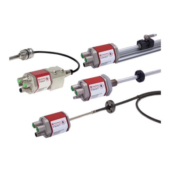
R-Series V POWERLINK Temposonics ® Operation Manual 4. Product description and commissioning 4.1 Functionality and system design Position magnet (magnetic fi eld) Product designation Sensing element (waveguide) R-Series V • Position sensor Temposonics ® Sensor model R-Series V RP5 (profile sensor) •... -
Page 11: Installation And Design Of Temposonics ® Rp5
R-Series V POWERLINK Temposonics ® Operation Manual 4.2 Installation and design of Temposonics ® RP5-M, example: Connection type D58 (connector outlet) Sensor electronics (0.2) housing Null zone Stroke length Dead zone 48 (1.89) 25…6350 66/71* (2.28) (1.1) (1…250) (2.6/2.8*) (0.67) e.g. for M5 or MS/ER #10 screws NS/RN Port 1 L/A L/A Port 2... -
Page 12: Installation And Design Of Temposonics ® Rh5
R-Series V POWERLINK Temposonics ® Operation Manual 4.3 Installation and design of Temposonics ® RH5-M/-S-A/-V – RH5 with threaded fl ange M18×1.5-6g or ¾"-16 UNF-3A, example: Connection type D58 (connector outlet) Sensor electronics housing Null zone Stroke length Dead zone 25…7620 63.5/66* (0.67) (2.68) (2.01) (1…300) (2.5/2.6*) MS/ER NS/RN Threaded flange »M«: M18×1.5-6g Threaded flange »S«: ¾"-16 UNF-3A (0.98) * Stroke length >... - Page 13 R-Series V POWERLINK Temposonics ® Operation Manual RH5-J-A/-V – RH5 with threaded fl ange M22×1.5-6g and Ø 12.7 mm rod, example: Connection type D56 (connector outlet) Sensor electronics housing Null zone Stroke length Dead zone 25…5900 73.6 (0.67) (2.68) (2.01) (1…232) (2.9) Threaded flange »J«: M22×1.5-6g (0.98) (2.09) RH5-B-A/-V – RH5 base unit (only for replacement), example: Connection type D58 (connector outlet) Sensor electronics housing Null zone Stroke length Dead zone 25…7620 52/54/57** (0.67)
- Page 14 R-Series V POWERLINK Temposonics ® Operation Manual Installation of RH5 with threaded flange In the case of threaded flange M18×1.5-6g or M22×1.5-6g, provide Fix the sensor rod via threaded flange M18×1.5-6g, M22×1.5-6g or a screw hole based on ISO 6149-1 (Fig. 11). See ISO 6149-1 for further ¾"-16 UNF-3A.
-
Page 15: Installation And Design Of Temposonics ® Rfv
R-Series V POWERLINK Temposonics ® Operation Manual 4.4 Installation and design of Temposonics ® RFV-B – RFV base unit, example: Connection type D56 (connector outlet) Sensor electronics housing Null zone Stroke length Dead zone 150…20,000 see table (0.67) (2.28) (2.4) (6…787) (0.28) Ø 8 ±0.23 (Ø 0.31±0.01) Stroke length Tolerance of total length Dead zone Up to 7620 mm (300.00 in.) +8 mm (0.31 in.)/−5 mm (0.20 in.) - Page 16 R-Series V POWERLINK Temposonics ® Operation Manual NOTICE 500 (20) recommended To fulfill the requirements of EMC standards for emission and Position magnet ≥ 300 (≥ 11.81) immunity the following points are necessary: • The sensor electronics housing has to be connected to machine Customized support tube ground (Fig.
- Page 17 R-Series V POWERLINK Temposonics ® Operation Manual Replacing an R-Series 2004 RF-C with an R-Series V RFV-B Hydraulics sealing when using an RFV sensor in a pressure rod HD/HL/HP If you are replacing the R-Series 2004 RF-C base unit with the R-Series V RFV-B base unit, note the following points: There are two ways to seal the flange contact surface (Fig.
-
Page 18: Installation And Design Of Temposonics ® Rdv
R-Series V POWERLINK Temposonics ® Operation Manual 4.5 Installation and design of Temposonics ® RDV with bottom cable entry, example: Connector D56 (connector outlet) 24.7 (0.97) (0.3) Ø 19 (Ø 0.75) Ø 26.2 (1.89) (Ø 1.03) (1.77) (2.28) (1.61) Recommendation: Use M6×45 (ISO 4762) screws Fastening torque: 6 Nm RDV with side cable entry, example: Connector D58 (connector outlet) 24.7 (0.97) - Page 19 R-Series V POWERLINK Temposonics ® Operation Manual Threaded fl ange »C« & »D« (for bottom or side cable entry) PUR cable: Ø 6 (Ø 0.24) Bending radius: Null zone Stroke length Dead zone > 24 (> 0.94) 25…5080 63.5/66* Cable length (bottom cable entry): (1.26) (2.01) (1…200) (2.5/2.6) 65/170/230/350 26.9 (2.6/6.7/9.1/13.8) (1.1) A/F 46...
- Page 20 R-Series V POWERLINK Temposonics ® Operation Manual NOTICE Installation of a rod-style sensor in a fluid cylinder The rod-style version has been developed for direct stroke measurement in a fluid cylinder. Mount the sensor via threaded flange or a hex nut. Note for installation respectively •...
- Page 21 R-Series V POWERLINK Temposonics ® Operation Manual Notice for metric threaded fl anges 4.5.2 Installation of RD with pressure fit flange Thread Z° ×P) Cylinder mounting +0.1 +0.4 ±1° Install the rod using the pressure fit flange. Seal it off by means of RDV-C the O-ring and the back-up ring.
- Page 22 R-Series V POWERLINK Temposonics ® Operation Manual NOTICE 4.5.3 Installation of RDV’s sensor electronics housing To fulfill the requirements of EMC standards for emission and The following section explains the connection of an RDV sensor with immunity the following points are necessary: bottom cable entry (Fig.
-
Page 23: Magnet Installation
R-Series V POWERLINK Temposonics ® Operation Manual Centered mounting 4.6 Magnet installation of block magnet Typical use of magnets Air gap: 3 ±2 Magnet Typical sensors Benefi ts 8 ±2 (0.12 ±0.08) (0.31 ±0.08) Ring magnets Rod model • Rotationally symmetrical Sensor element (RH5, RFV, RDV) magnetic fi eld Block magnet... - Page 24 R-Series V POWERLINK Temposonics ® Operation Manual RFV-B with ring magnet/U-magnet Start- and end positions of the position magnets Consider the start and end positions of the position magnets during Sensor electronics housing the installation. To ensure that the entire stroke length is electrically Reference edge of mounting usable, the position magnet must be mechanically mounted as follows.
- Page 25 R-Series V POWERLINK Temposonics ® Operation Manual RFV-B with block magnet RDV-S with block magnet Reference edge of mounting Sensor electronics housing Reference edge of mounting Start position End position 21.4 (0.84) 63.5 (2.5) End position Start position 58.5 (2.3) See table RDV-M/-T with block magnet Reference edge of mounting Start position End position...
- Page 26 R-Series V POWERLINK Temposonics ® Operation Manual Multi-position measurement The minimum distance between the magnets is 75 mm (3 in.). RP5 with U-magnets ≥ 75 (≥ 3) RP5 with magnet sliders ≥ 75 (≥ 3) RP5 with block magnets ≥ 75 (≥ 3) RH5 & RFV with ring magnets/U-magnets ≥ 75 (≥ 3) RH5 & RFV with block magnets ≥...
-
Page 27: Alignment Of The Magnet With The Option "Internal Linearization
R-Series V POWERLINK Temposonics ® Operation Manual 4.7 Alignment of the magnet with the option For RP5 POWERLINK sensors with U-magnet applies: “Internal linearization” • Install the magnet until the marking on the magnet points to the sensor electronics housing. The internal linearization offers improved linearity of the sensor. - Page 28 R-Series V POWERLINK Temposonics ® Operation Manual For RDV POWERLINK sensors with ring magnet/U-magnet applies: • Install the magnet so that the marking on the magnet faces the sensor flange. • The marking on the magnet points in the same direction as the marking on the sensor flange.
-
Page 29: Replacement Of Base Unit
R-Series V POWERLINK Temposonics ® Operation Manual 3. Insert the new base unit. 4.8 Replacement of base unit Mount the ground lug on a screw. Tighten the screws. The base unit of the sensor model RH5 (RH5-B) is replaceable as shown in Fig. 45 and Fig. 46 for the sensor designs »M«, »S« and »T«. -
Page 30: Electrical Connection
R-Series V POWERLINK Temposonics ® Operation Manual 4.9 Electrical connection Connector wiring Connect the sensor directly to the control system, indicator or other Placement of installation and cabling have decisive influence on evaluating systems as follows: the sensor‘s electromagnetic compatibility (EMC). Hence correct installation of this active electronic system and the EMC of the entire Port 1 Port 2... - Page 31 R-Series V POWERLINK Temposonics ® Operation Manual Port 1 – Signal M12 female connector Function (D-coded) Tx (+) Rx (+) Tx (−) View on sensor Rx (−) Port 2 – Signal M12 female connector Function (D-coded) Tx (+) Rx (+) Tx (−) View on sensor Rx (−) Power supply M12 male connector Function (A-coded) +12…30 VDC (±20 %) Not connected...
-
Page 32: Frequently Ordered Accessories For Rp5 Design
R-Series V POWERLINK Temposonics ® Operation Manual 4.10 Frequently ordered accessories for RP5 design – Additional options see Accessories Catalog 551444 Position magnets 15.2 57 (2.24) (0.6) (1.65) (1.69) (0.94) (1.69) (0.55) (0.55) 49 (1.93) (0.79) (0.79) (0.79) 40 (1.57) 40 (1.57) 40 (1.57) 40 (1.57) Magnet slider S, joint at top... -
Page 33: Frequently Ordered Accessories For Rh5 Design
R-Series V POWERLINK Temposonics ® Operation Manual 4.11 Frequently ordered accessories for RH5 design – Additional options see Accessories Catalog 551444 Position magnets Ø 32.8 (Ø 1.29) Ø 4.3 Ø 32.8 Ø 30.5 Ø 25.4 (Ø 0.17) (Ø 1.29) (Ø 1.2) (Ø... -
Page 34: Frequently Ordered Accessories For Rfv Design
R-Series V POWERLINK Temposonics ® Operation Manual 4.12 Frequently ordered accessories for RFV design – Additional options see Accessories Catalog 551444 Position magnets Ø 32.8 Ø 4.5 (Ø 0.18) Ø 60 Ø 63.5 (Ø 1.29) Ø 30.5 Ø 4.3 (Ø 2.36) (Ø... - Page 35 R-Series V POWERLINK Temposonics ® Operation Manual Mounting accessories Pressure rod with threaded fl ange Pressure rod with threaded fl ange Profi le with fl ange with fl at-face (M18×1.5-6g) with fl at-face (¾"-16 UNF-3A) HFP [length mm: XXXXX] M and O-ring and O-ring HFP [length in.: XXXX.X] U HD [length mm: XXXX] M HL [length mm: XXXX] M HD [length in.: XXX.X] U HL [length in.: XXX.X] U Pressure rod Ø: 12.7 mm (0.5 in.) Pressure rod Ø: 12.7 mm (0.5 in.) Length: Max.
-
Page 36: Frequently Ordered Accessories For Rdv Design
R-Series V POWERLINK Temposonics ® Operation Manual 4.13 Frequently ordered accessories for RDV design – Additional options see Accessories Catalog 551444 Position magnets Ø 32.8 (Ø 1.29) Ø 4.3 Ø 32.8 Ø 17.4 Ø 25.4 (Ø 0.17) (Ø 1.29) (Ø 0.69) (Ø... - Page 37 R-Series V POWERLINK Temposonics ® Operation Manual Mounting accessory 60 (2.36) 16 (0.63) Ø 3.2 (Ø 0.13) M3 fastening screws (6×) 3.2 (0.13) Fixing clip Part no. 561 481 Application: Used to secure sensor rods (Ø 10 mm (Ø 0.39 in.)) when using an U-magnet or block magnet Material: Brass, non-magnetic Controlling design dimensions are in millimeters and measurements in ( ) are in inches...
-
Page 38: Frequently Ordered Accessories For Powerlink Output
R-Series V POWERLINK Temposonics ® Operation Manual 4.14 Frequently ordered accessories for POWERLINK output – Additional options see Accessories Catalog 551444 Cable connectors* – Signal Cable connectors* – Power (2.05) (2.09) (1.7) (0.24) (0.63) M12 D-coded male connector M12 connector end cap M12 A-coded female connector M8 female connector (4 pin), straight (4 pin), straight Part no. 370 537 (4 pin/5 pin), straight Part no. 370 504 Part no. 370 523 Part no. 370 677 Material: Zinc nickel-plated Female connectors M12 should be... - Page 39 R-Series V POWERLINK Temposonics ® Operation Manual Cable sets Programming tools Power cable with M8 female connector Power cable with M12 A-coded female TempoLink kit for Temposonics TempoGate smart assistant for ® ® ® R-Series V (4 pin), straight – pigtail connector (5 pin), straight – pigtail R-Series V Temposonics ® Part no. 530 066 (5 m (16.4 ft.)) Part no. 370 673 Part no. TL-1-0-EM08 (D56) Part no. TG-C-0-Dxx (xx indicates the number of R-Serie V Part no. 530 096 (10 m (32.8 ft.)) Part no. TL-1-0-EM12 (D58) Part no. 530 093 (15 m (49.2 ft.))
-
Page 40: Operation
Green Information R-Series V POWERLINK Temposonics ® - Number of magnets differs from Operation Manual confi guration - Power supply outside specifi cation Flashing - Invalid confi guration of the sensor - Internal error 5. Operation Bus status LED (when the sensor is started up, these statuses run through) 5.1 Initial start-up MS/ER The position sensor R-Series V POWERLINK transfers position... -
Page 41: Topologies And Hubs
R-Series V POWERLINK Temposonics ® Operation Manual 6. Node ID configuration of R-Series V POWERLINK 5.3 Topologies and hubs This chapter describes how to adjust the node ID of the R-Series V POWERLINK supports various topologies when building up a network. Thus, the usage of linear, star, ring and tree topologies POWERLINK. - Page 42 R-Series V POWERLINK Temposonics ® Operation Manual Connect the TempoLink smart assistant to the power supply using Connect the USB cable with the micro USB connector to the port ® the plug-in power supply with plug adapters. Connect the barrel labeled “USB”...
- Page 43 R-Series V POWERLINK Temposonics ® Operation Manual 6.1.4 Graphical User Interface (GUI) Click the menu symbol in the top left to get to the main menu: Fig. 61: Changing the node ID of the connected sensor After the node ID has been configured, click the EXIT COMMAND MODE button.
-
Page 44: Setting The Node Id Via "Automation Studio
R-Series V POWERLINK Temposonics ® Operation Manual Name Description 6.2 Setting the node ID via “Automation Studio” STATE_SEARCH_FOR_NODE This is the initial state in this project. In this state, PLC tries to read the vendor ID of The following is a description how to set the node ID of the controlled nodes starting from node ID 1 up to R-Series POWERLINK as well as the R-Series V POWERLINK using node ID 239 (all node IDs which are supposed... - Page 45 R-Series V POWERLINK Temposonics ® Operation Manual 6.2.4 Program executed by PLC once after start-up (SdoAccessInit.c) This program initializes the state of the implemented state machine as well as the node ID variable. It also sets the variable which is used to store the node ID of the first found controlled node with vendor ID from Temposonics to a value which is invalid for a controlled node (source code below).
- Page 46 R-Series V POWERLINK Temposonics ® Operation Manual Source Code “SdoAccessCyclic.c” /******************************************************************** * COPYRIGHT -- ******************************************************************** * Program: SdoAccess * File: SdoAccessCyclic.c * Author: SSchumacher * Created: November 18, 2014 ******************************************************************** * Implementation of program SdoAccess ********************************************************************/ #include <bur/plctypes.h> #ifdef _DEFAULT_INCLUDES #include <AsDefault.h>...
- Page 47 R-Series V POWERLINK Temposonics ® Operation Manual 6.2.6 Variable watch after successful execution of the implemented state machine As shown in the screenshot of the variable watch, a controlled node with vendor ID from Temposonics has been found at node ID 32. The node ID has been successfully set to 1.
-
Page 48: Integration Of R-Series V Powerlink In The Control System
R-Series V POWERLINK Temposonics ® Operation Manual 7. Integration of R-Series V POWERLINK in the control system Navigate to the location where the XDD file for the R-Series V Project integration The project integration is described using an example with a B&R POWERLINK is stored. - Page 49 R-Series V POWERLINK Temposonics ® Operation Manual Adding R-Series V POWERLINK to a network As in the system designer also in the physical view on the left the sensor is connected to the control. To enable the control to In the right of the main view is the “Toolbox - Hardware Catalog”. Choose the R-Series V POWERLINK in the “Toolbox - Hardware communicate with the sensor, the node ID previously set on the Catalog”...
- Page 50 R-Series V POWERLINK Temposonics ® Operation Manual The available configuration data of the sensor is divided into two groups: • Channels: Measurement data of the sensor, that can be transferred cyclically. To activate cyclic transmission of a specific data item, click on the data item column called "Value"...
-
Page 51: Communication Segment
R-Series V POWERLINK Temposonics ® Operation Manual 7.2 Communication segment The parameters of the group “Channels” (available data items for cyclical transmission): Index Subindex Name Object type Attribute Data type Description 2302 Number of detected magnets Variable Unsigned8 Current number of magnets detected on the sensor 2303 PSU voltage Current power supply in mV... - Page 52 R-Series V POWERLINK Temposonics ® Operation Manual The parameters of the group “Device Specific Parameters”: Index Subindex Name Object type Attribute Data type Description 2201 Number of magnets Variable Unsigned8 Setting the number of position magnets that are used simultaneously on the measuring rod/profile Note: If the number is greater than in the order code, an alarm is issued.
- Page 53 R-Series V POWERLINK Temposonics ® Operation Manual Index Subindex Name Object type Attribute Data type Description 6010 The preset can be set for up to 30 magnets. Preset values for multi-sensor devices Array Number of entries Variable Unsigned8 1…30 Preset for 1…30 magnets Variable Integer32 6301 CAM enable register Via the “CAM enable register”...
- Page 54 R-Series V POWERLINK Temposonics ® Operation Manual Index Subindex Name Object type Attribute Data type Description This object contains the position value, at which bit 2 of the according 6401 Work area low limit Array p406_work_area_state_channel in object 6400h (Working Area State Number of entries Variable Unsigned8...
-
Page 55: Maintenance And Troubleshooting
R-Series V POWERLINK Temposonics ® Operation Manual 8. Maintenance and troubleshooting 8.1 Error conditions, troubleshooting See chapter “5. Operation” on page 40. 8.2 Maintenance The sensor is maintenance-free. 8.3 Repair Repairs of the sensor may be performed only by Temposonics or a repair facility explicitly authorized by Temposonics. -
Page 56: Technical Data
R-Series V POWERLINK Temposonics ® Operation Manual 10. Technical data 10.1 Technical data Temposonics ® Output Interface Ethernet POWERLINK Data protocol POWERLINK V2 Measured value Position, velocity/option: Simultaneous multi-position and multi-velocity measurements up to 30 magnets Measurement parameters Resolution: Position 0.5…100 µm (selectable) Cycle time Stroke length... -
Page 57: Technical Data Temposonics ® Rh5
R-Series V POWERLINK Temposonics ® Operation Manual 10.2 Technical data Temposonics ® Output Interface Ethernet POWERLINK Data protocol POWERLINK V2 Measured value Position, velocity/option: Simultaneous multi-position and multi-velocity measurements up to 30 magnets Measurement parameters Resolution: Position 0.5…100 µm (selectable) Cycle time Stroke length ≤... -
Page 58: Technical Data Temposonics ® Rfv
R-Series V POWERLINK Temposonics ® Operation Manual 10.3 Technical data Temposonics ® Output Interface Ethernet POWERLINK Data protocol POWERLINK V2 Measured value Position, velocity/option: Simultaneous multi-position and multi-velocity measurements up to 30 magnets Measurement parameters Resolution: Position 0.5…100 µm (selectable) Cycle time Stroke length ≤... -
Page 59: Technical Data Temposonics ® Rdv
R-Series V POWERLINK Temposonics ® Operation Manual 10.4 Technical data Temposonics ® Output Interface Ethernet POWERLINK Data protocol POWERLINK V2 Measured value Position, velocity/option: Simultaneous multi-position and multi-velocity measurements up to 30 magnets Measurement parameters Resolution: Position 0.5…100 µm (selectable) Cycle time Stroke length ≤... - Page 60 11. Appendix I Safety declaration Dear Customer, If you return one or several sensors for checking or repair, we need you to sign a safety declaration. The purpose of this declaration is to ensure that the returned items do not contain residues of harmful substances and/or that people handling these items will not be in danger. Temposonics order number: __________________________ Sensor type(s): ____________________________________________ Serial number(s): __________________________________...
- Page 61 R-Series V POWERLINK Temposonics ® Operation Manual 12. Appendix II C Y L I N D E R P O R T D E T A I L S P O R T D E T A I L ( P D ) F O R R H 5 - S : NOTES: 1.
-
Page 62: Glossary
R-Series V POWERLINK Temposonics ® Operation Manual 13. Glossary Managing Node (MN) The Managing Node (MN), usually an industrial PC or a PLC, con- Cam position of a CAM channel in a cam gear. Each CAM position can be confi gured separately. With R-Series V POWERLINK, for each po- trols the communication in the network as master and sets the clock for the synchronization of all devices. - Page 63 R-Series V POWERLINK Temposonics ® Operation Manual Synchronization mode R-Series V POWERLINK supports synchronization mode. The syn- chronization mode enables clock-synchronous data exchange be- tween sensor and control. The synchronous measurement is an es- sential requirement for motion-controlled applications Vendor ID A unique identifi cation number (ID) assigned to each piece of computer hardware.
- Page 64 © 2022 Temposonics, LLC – all rights reserved. Temposonics, LLC and Temposonics GmbH & Co. KG are subsidiaries of Amphenol Corporation. Except for any third party marks for which attribution is provided herein, the company names and product names used in this document may be the registered trademarks or unregistered trademarks of Temposonics, LLC or...
Need help?
Do you have a question about the Temposonics V POWERLINK R Series and is the answer not in the manual?
Questions and answers