
Subscribe to Our Youtube Channel
Related Manuals for Amphenol Temposonics V EtherNet/IP R Series


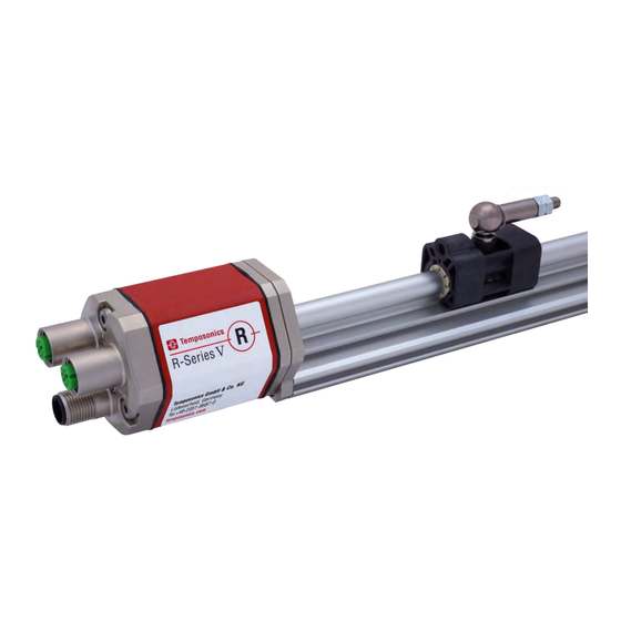
Summary of Contents for Amphenol Temposonics V EtherNet/IP R Series
- Page 1 Operation Manual R-Series V EtherNet/IP™ Magnetostrictive Lineare Position Sensors...
-
Page 2: Table Of Contents
R-Series V EtherNet/IP™ Temposonics ® Operation Manual Table of contents 1. Introduction ..............................3 1.1 Purpose and use of this manual ................................3 1.2 Used symbols and warnings ..................................3 2. Safety instructions ............................. 3 2.1 Intended use ......................................3 2.2 Foreseeable misuse .................................... -
Page 3: Introduction
R-Series V EtherNet/IP™ Temposonics ® Operation Manual 1. Introduction 2.2 Foreseeable misuse Foreseeable misuse Consequence 1.1 Purpose and use of this manual The sensor will not work Wrong sensor connection properly or can be damaged Before starting the operation of Temposonics position sensors, ®... -
Page 4: Installation, Commissioning And Operation
R-Series V EtherNet/IP™ Temposonics ® Operation Manual 2.3 Installation, commissioning and operation 2.5 Warranty The position sensors must be used only in technically safe conditions. Temposonics grants a warranty period for the position sensors and To maintain this condition and to ensure safe operation, installation, supplied accessories relating to material defects and faults that occur connection and service, work may be performed only by qualified despite correct use in accordance with the intended application... -
Page 5: Identification
R-Series V EtherNet/IP™ Temposonics ® Operation Manual 3. Identification 3.1 Order code of Temposonics ® a Sensor model e Number of magnets 5 Profi le X 01…20 Position(s) (1…20 magnet(s)) b Design f Connection type G Magnet slider backlash free (part no. 253 421), 6 2 ×... -
Page 6: Order Code Of Temposonics ® Rh5
R-Series V EtherNet/IP™ Temposonics ® Operation Manual 3.2 Order code of Temposonics ® a Sensor model e Number of magnets 5 Rod X 01…20 Position(s) (1…20 magnet(s)) b Design f Connection type 6 2 × M12 female connectors (D-coded), B Base unit (only for replacement) 1 ×... -
Page 7: Order Code Of Temposonics ® Rfv
R-Series V EtherNet/IP™ Temposonics ® Operation Manual 3.3 Order code of Temposonics ® a Sensor model e Number of magnets V Flexible rod X 01…20 Position(s) (1…20 magnet(s)) b Design f Connection type 6 2 × M12 female connectors (D-coded), B Base unit 1 ×... -
Page 8: Rdv
R-Series V EtherNet/IP™ Temposonics ® Operation Manual 3.4 Order code of Temposonics ® a Design e Number of magnets V Detached sensor electronics “Classic” X 01…20 Position(s) (1…20 magnet(s)) b Design f Connection type 6 2 × M12 female connectors (D-coded), C Threaded fl ange M18×1.5-6g (A/F 46) 1 ×... -
Page 9: Nameplate
R-Series V EtherNet/IP™ Temposonics ® Operation Manual 3.5 Nameplate Order code RH5SA0080U01D561U201 MAC address MAC: 00-03-CA-00-58-F6 Serial number S/N: 70008887 Date of production 01AUG2022 Fig. 1: Example of nameplate of a R-Series V RH5 sensor with EtherNet/IP™ output 3.6 Approvals •... -
Page 10: Product Description And Commissioning
R-Series V EtherNet/IP™ Temposonics ® Operation Manual 4. Product description and commissioning 4.1 Functionality and system design Position magnet (magnetic fi eld) Product designation Sensing element (waveguide) R-Series V • Position sensor Temposonics ® Sensor model R-Series V RP5 (profile sensor) •... -
Page 11: Installation And Design Of Temposonics ® Rp5
R-Series V EtherNet/IP™ Temposonics ® Operation Manual 4.2 Installation and design of Temposonics ® RP5-M, example: Connection type D58 (connector outlet) Sensor electronics (0.2) housing Null zone Stroke length Dead zone 48 (1.89) 25…6350 66/71* (2.28) (1.1) (1…250) (2.6/2.8*) (0.67) e.g. for M5 or MS/ER #10 screws NS/RN Port 1 L/A L/A Port 2... -
Page 12: Installation And Design Of Temposonics ® Rh5
R-Series V EtherNet/IP™ Temposonics ® Operation Manual 4.3 Installation and design of Temposonics ® RH5-M/-S-A/-V – RH5 with threaded fl ange M18×1.5-6g or ¾"-16 UNF-3A, example: Connection type D58 (connector outlet) Sensor electronics housing Null zone Stroke length Dead zone 25…7620 63.5/66* (0.67) (2.68) (2.01) (1…300) (2.5/2.6*) MS/ER NS/RN Threaded flange »M«: M18×1.5-6g Threaded flange »S«: ¾"-16 UNF-3A (0.98) * Stroke length >... - Page 13 R-Series V EtherNet/IP™ Temposonics ® Operation Manual RH5-J-A/-V – RH5 with threaded fl ange M22×1.5-6g and Ø 12.7 mm rod, example: Connection type D56 (connector outlet) Sensor electronics housing Null zone Stroke length Dead zone 25…5900 73.6 (0.67) (2.68) (2.01) (1…232) (2.9) Threaded flange »J«: M22×1.5-6g (0.98) (2.09) RH5-B-A/-V – RH5 base unit (only for replacement), example: Connection type D58 (connector outlet) Sensor electronics housing Null zone Stroke length Dead zone 25…7620 52/54/57**...
- Page 14 R-Series V EtherNet/IP™ Temposonics ® Operation Manual Installation of RH5 with threaded flange In the case of threaded flange M18×1.5-6g or M22×1.5-6g, provide Fix the sensor rod via threaded flange M18×1.5-6g, M22×1.5-6g or a screw hole based on ISO 6149-1 (Fig. 11). See ISO 6149-1 for further ¾"-16 UNF-3A.
-
Page 15: Rfv
R-Series V EtherNet/IP™ Temposonics ® Operation Manual 4.4 Installation and design of Temposonics ® RFV-B – RFV base unit, example: Connection type D56 (connector outlet) Sensor electronics housing Null zone Stroke length Dead zone 150…20,000 see table (0.67) (2.28) (2.4) (6…787) (0.28) Ø 8 ±0.23 (Ø 0.31±0.01) Stroke length Tolerance of total length Dead zone Up to 7620 mm (300.00 in.) +8 mm (0.31 in.)/−5 mm (0.20 in.) - Page 16 R-Series V EtherNet/IP™ Temposonics ® Operation Manual 500 (20) recommended Position magnet ≥ 300 (≥ 11.81) Customized support tube required e.g. Ø 12.7 × 1.65 (0.4) (Ø 0.5 × 0.65), inside Ø 9.4 (Ø 0.37), non-magnetic Installation of RFV with threaded flange »M«, »S« Fix the sensor rod via threaded flange M18×1.5-6g or ¾"-16 UNF-3A. Note the fastening torque of RFV-M: 65 Nm Flange M18×1.5-6g...
- Page 17 R-Series V EtherNet/IP™ Temposonics ® Operation Manual Replacing an R-Series 2004 RF-C with an R-Series V RFV-B. Hydraulics sealing when using an RFV sensor in a pressure rod HD/ HL/HP If you are replacing the R-Series 2004 RF-C base unit with the R-Series V RFV-B base unit, note the following points: There are two ways to seal the flange contact surface (Fig.
-
Page 18: Rdv
R-Series V EtherNet/IP™ Temposonics ® Operation Manual 4.5 Installation and design of Temposonics ® RDV with bottom cable entry, example: Connector D56 (connector outlet) 24.7 (0.97) (0.3) Ø 19 (Ø 0.75) Ø 26.2 (1.89) (Ø 1.03) (1.77) (2.28) (1.61) Recommendation: Use M6×45 (ISO 4762) screws Fastening torque: 6 Nm RDV with side cable entry, example: Connector D58 (connector outlet) 24.7 (0.97) - Page 19 R-Series V EtherNet/IP™ Temposonics ® Operation Manual Threaded fl ange »C« & »D« (for bottom or side cable entry) PUR cable: Ø 6 (Ø 0.24) Bending radius: Null zone Stroke length Dead zone > 24 (> 0.94) 25…5080 63.5/66* Cable length (bottom cable entry): (1.26) (2.01) (1…200) (2.5/2.6) 65/170/230/350 26.9 (2.6/6.7/9.1/13.8) (1.1)
- Page 20 R-Series V EtherNet/IP™ Temposonics ® Operation Manual NOTICE Installation of a rod-style sensor in a fluid cylinder The rod-style version has been developed for direct stroke measurement in a fluid cylinder. Mount the sensor via threaded flange or a hex nut. Note for installation respectively • Mounted on the face of the piston, the position magnet travels for replacement of RDV over the rod without touching it and indicates the exact position The serial numbers (S/N) of cable...
- Page 21 R-Series V EtherNet/IP™ Temposonics ® Operation Manual Notice for metric threaded fl anges 4.5.2 Installation of RD4 with pressure fit flange Thread Z° ×P) Cylinder mounting +0.1 +0.4 ±1° Install the rod using the pressure fit flange. Seal it off by means of RDV-C the O-ring and the back-up ring. Block the pressure fit flange using a M18×1.5-6g 55 ≥...
- Page 22 R-Series V EtherNet/IP™ Temposonics ® Operation Manual NOTICE 4.5.4 Installation of RDV’s sensor electronics housing To fulfill the requirements of EMC standards for emission and The following section explains the connection of a RDV sensor with immunity the following points are necessary: bottom cable entry (Fig.
-
Page 23: Magnet Installation
R-Series V EtherNet/IP™ Temposonics ® Operation Manual Centered mounting 4.6 Magnet installation of block magnet Typical use of magnets Air gap: 3 ±2 Magnet Typical sensors Benefi ts 8 ±2 (0.12 ±0.08) (0.31 ±0.08) Ring magnets Rod model • Rotationally symmetrical Sensor element (RH5, RFV, RDV) magnetic fi eld... - Page 24 R-Series V EtherNet/IP™ Temposonics ® Operation Manual RFV-B with ring magnet/U-magnet Start- and end positions of the position magnets Consider the start and end positions of the position magnets during Sensor electronics housing the installation. To ensure that the entire stroke length is electrically Reference edge of mounting usable, the position magnet must be mechanically mounted as follows.
- Page 25 R-Series V EtherNet/IP™ Temposonics ® Operation Manual RFV-B with block magnet RDV-S with block magnet Reference edge of mounting Sensor electronics housing Reference edge of mounting Start position End position 21.4 (0.84) 63.5 (2.5) End position Start position 58.5 (2.3) See table RDV-M/-T with block magnet Reference edge of mounting...
- Page 26 R-Series V EtherNet/IP™ Temposonics ® Operation Manual Multi-position measurement The minimum distance between the magnets is 75 mm (3 in.). RP5 with U-magnets ≥ 75 (≥ 3) RP5 with magnet sliders ≥ 75 (≥ 3) RP5 with block magnets ≥ 75 (≥ 3) RH5 & RFV with ring magnets/U-magnets ≥...
-
Page 27: Alignment Of The Magnet With The Option "Internal Linearization
R-Series V EtherNet/IP™ Temposonics ® Operation Manual 4.7 Alignment of the magnet with the option For RP5 EtherNet/IP™ sensors with U-magnet applies: “Internal linearization” • Install the magnet until the marking on the magnet points to the sensor electronics housing. The internal linearization offers improved linearity of the sensor. •... - Page 28 R-Series V EtherNet/IP™ Temposonics ® Operation Manual For RDV EtherNet/IP™ sensors with ring magnet/U-magnet applies: • Install the magnet so that the marking on the magnet faces the sensor flange. • The marking on the magnet points in the same direction as the marking on the sensor flange. Marking Marking Fig.
-
Page 29: Replacement Of Base Unit
R-Series V EtherNet/IP™ Temposonics ® Operation Manual 3. Insert the new base unit. 4.8 Replacement of base unit Mount the ground lug on a screw. Tighten the screws. The base unit of the sensor model RH5 (RH5-B) is replaceable as shown in Fig. -
Page 30: Electrical Connection
R-Series V EtherNet/IP™ Temposonics ® Operation Manual 4.9 Electrical connection Connector wiring Connect the sensor directly to the control system, indicator or other Placement of installation and cabling have decisive influence on evaluating systems as follows: the sensor‘s electromagnetic compatibility (EMC). Hence correct installation of this active electronic system and the EMC of the entire Port 1 Port 2... - Page 31 R-Series V EtherNet/IP™ Temposonics ® Operation Manual Port 1 – Signal M12 female connector Function (D-coded) Tx (+) Rx (+) Tx (−) View on sensor Rx (−) Port 2 – Signal M12 female connector Function (D-coded) Tx (+) Rx (+) Tx (−) View on sensor Rx (−)
-
Page 32: Frequently Ordered Accessories For Rp5 Design
R-Series V EtherNet/IP™ Temposonics ® Operation Manual 4.10 Frequently ordered accessories for RP5 design – Additional options see Accessories Catalog 551444 Position magnets 15.2 57 (2.24) (0.6) (1.65) (1.69) (0.94) (1.69) (0.55) (0.55) 49 (1.93) (0.79) (0.79) (0.79) 40 (1.57) 40 (1.57) 40 (1.57) 40 (1.57) -
Page 33: Frequently Ordered Accessories For Rh5 Design
R-Series V EtherNet/IP™ Temposonics ® Operation Manual 4.11 Frequently ordered accessories for RH5 design – Additional options see Accessories Catalog 551444 Position magnets Ø 32.8 (Ø 1.29) Ø 4.3 Ø 32.8 Ø 30.5 Ø 25.4 (Ø 0.17) (Ø 1.29) (Ø 1.2) (Ø... -
Page 34: Frequently Ordered Accessories For Rfv Design
R-Series V EtherNet/IP™ Temposonics ® Operation Manual 4.12 Frequently ordered accessories for RFV design – Additional options see Accessories Catalog 551444 Position magnets Ø 32.8 Ø 4.5 (Ø 0.18) Ø 60 Ø 63.5 (Ø 1.29) Ø 30.5 Ø 4.3 (Ø 2.36) (Ø... - Page 35 R-Series V EtherNet/IP™ Temposonics ® Operation Manual Mounting accessories Pressure rod with threaded fl ange Pressure rod with threaded fl ange Profi le with fl ange with fl at-face (M18×1.5-6g) with fl at-face (¾"-16 UNF-3A) HFP [length mm: XXXXX] M and O-ring and O-ring HFP [length in.: XXXX.X] U HD [length mm: XXXX] M HL [length mm: XXXX] M HD [length in.: XXX.X] U HL [length in.: XXX.X] U Pressure rod Ø: 12.7 mm (0.5 in.) Pressure rod Ø: 12.7 mm (0.5 in.) Length: Max.
-
Page 36: Frequently Ordered Accessories For Rdv Design
R-Series V EtherNet/IP™ Temposonics ® Operation Manual 4.13 Frequently ordered accessories for RDV design – Additional options see Accessories Catalog 551444 Position magnets Ø 32.8 (Ø 1.29) Ø 4.3 Ø 32.8 Ø 17.4 Ø 25.4 (Ø 0.17) (Ø 1.29) (Ø 0.69) (Ø... - Page 37 R-Series V EtherNet/IP™ Temposonics ® Operation Manual Mounting accessory 60 (2.36) 16 (0.63) Ø 3.2 (Ø 0.13) M3 fastening screws (6×) 3.2 (0.13) Fixing clip Part no. 561 481 Application: Used to secure sensor rods (Ø 10 mm (Ø 0.39 in.)) when using an U-magnet or block magnet Material: Brass, non-magnetic Controlling design dimensions are in millimeters and measurements in ( ) are in inches...
-
Page 38: Frequently Ordered Accessories For Ethnernet/Ip™ Output
R-Series V EtherNet/IP™ Temposonics ® Operation Manual 4.14 Frequently ordered accessories for EthnerNet/IP™ output Cable connectors* – Signal Cable connectors* – Power (2.05) (2.09) (1.7) (0.24) (0.63) M12 D-coded male connector M12 connector end cap M12 A-coded female connector M8 female connector (4 pin), straight (4 pin), straight Part no. - Page 39 R-Series V EtherNet/IP™ Temposonics ® Operation Manual Cable sets Programming tools Power cable with M8 female connector Power cable with M12 A-coded female TempoLink kit for Temposonics ® ® TempoGate smart assistant for ® R-Series V R-Series V (4 pin), straight – pigtail connector (5 pin), straight –...
-
Page 40: Operation
Green Information Connection established R-Series V EtherNet/IP™ Temposonics ® Operation Manual Flashing No connection Unrecoverable error Flashing Recoverable error 5. Operation Port 1 L/A (IN) 5.1 Initial start-up MS/ER The position sensor R-Series V EtherNet/IP™ transfers position NS/RN and velocity values via the EtherNet/IP™ output. EtherNet/IP™ is the abbreviation for Ethernet Industrial Protocol. -
Page 41: Programming And Configuration
R-Series V EtherNet/IP™ Temposonics ® Operation Manual 6. Programming and configuration NOTICE 1. Choose an IP address that is not being used on your network or subnetwork. 6.1 IP address Configuration 2. After the IP address is assigned to the sensor, record the IP address and have it available as you will need it to communicate An example of configuring a Temposonics EtherNet/IP™... - Page 42 R-Series V EtherNet/IP™ Temposonics ® Operation Manual 6.2.5 Apply power to the sensor. The sensor should take around 10 to 6.2.9 Exit the BOOT/DHCP Server software. If installing the 15 seconds to begin to broadcast its MAC ID. Temposonics EtherNet/IP™ EDS file (download at www. 6.2.6 Verify that your IP address and MAC ID appear in the ‘Request temposonics.com) continue with chapter 7.1.
-
Page 43: Integration In Rslogix 5000
R-Series V EtherNet/IP™ Temposonics ® Operation Manual 7. Integration in RSLogix 5000 7.1 Install the Temposonics EtherNet/IP™ EDS file 7.1.3 The ‘EDS Wizard’ window opens, click Next, in the ‘Options’ window select Register an EDS file(s) and click “Next”. The EDS file for the R-Series V EtherNet/IP™ sensor is available at www.temposonics.com. - Page 44 R-Series V EtherNet/IP™ Temposonics ® Operation Manual 7.1.4 The ‘Registration’ window opens, click "Browse" and select the 7.1.6 The ‘Final Task Summary’ window opens, click “Next”. EDS file provided either with the sensor or downloaded from the Temposonics website. Click “Next”. Fig.
-
Page 45: Add Sensor To I/O Configuration Using Eds File
R-Series V EtherNet/IP™ Temposonics ® Operation Manual 7.2 Add sensor to I/O configuration using EDS file 7.2.2 In the Select Module Type window, choose “R-Series EtherNet/ IP” and click “Create”. 7.2.1 After completing the EDS wizard, return to the main window of RSLogix 5000. In the controller organizer sidebar, expand the I/O Configuration tree and right-click your network. -
Page 46: Add Sensor To I/O Configuration Without Using Eds File
R-Series V EtherNet/IP™ Temposonics ® Operation Manual 7.2.4 Verify that the new sensor is listed in the I/O Configuration tree. 7.3 Add sensor to I/O configuration without using EDS file Before you begin, you will need the sensors static IP address you recorded in from step 6.2.7. 7.3.1 Open the RSLogix 500 software interface. 7.3.2 Open the controllers’... -
Page 47: Set Module Rpi
R-Series V EtherNet/IP™ Temposonics ® Operation Manual 7.3.4 In the ‘New Module’ window (Fig. 71) perform step 7.3.4.1 – 7.4 Set Module RPI 7.3.4.4 to configure the new generic ethernet module to the 7.4.1 Click the “Connection” tab. Set the “Requested Packet Interval” R-Series EtherNet/IP™... -
Page 48: Verify Generic Ethernet Module
R-Series V EtherNet/IP™ Temposonics ® Operation Manual 7.6 Verify Generic Ethernet Module 7.6.1 In the ‘I/O configuration tree’, click to open the ‘Controller Tags’ directory. The controller tag table displays in the left pane (Fig. 74). The description column fields will be blank by default. Fig. - Page 49 R-Series V EtherNet/IP™ Temposonics ® Operation Manual 7.6.3 Locate Data Byte [0] through [5] In the ‘Name’ column. In the ‘Description’ column, enter the following Data Byte field information. Name Description Values Description Data Byte [0] Data format 4 bytes signed position, 4 bytes signed velocity (repeats for each magnet) 4 bytes signed position (repeats for each magnet) 4 bytes signed velocity (repeats for each magnet) (default value)
-
Page 50: Controller Tags Input Data
R-Series V EtherNet/IP™ Temposonics ® Operation Manual 7.7 Controller tags input data The following illustrates an example of 'Controller Tags' information based on the factory default configuration: Fig. 75: Controller tags 'Controller Tags' information Examples based on the factory default configuration are as follows: 7.7.1 Run/Idle Header Data[0] is always the Run/Idle header. This is not required by the EtherNet/IP™ standard, but it is highly recommended. It can be used by the end user to determine if the system is in Run or Idle mode. -
Page 51: Maintenance And Troubleshooting
R-Series V EtherNet/IP™ Temposonics ® Operation Manual 8. Maintenance and troubleshooting 8.1 Error conditions, troubleshooting See chapter "5. Operation" on page 40. 8.2 Maintenance The sensor is maintenance-free. 8.3 Repair Repairs of the sensor may be performed only by Temposonics or a repair facility explicitly authorized by Temposonics. -
Page 52: Technical Data
R-Series V EtherNet/IP™ Temposonics ® Operation Manual 10. Technical data 10.1 Technical data Temposonics ® Output Interface EtherNet/IP™ Data protocol Encoder CIP device profile with CIP Sync™ and DLR capabilities Data transmission rate 100 MBit/s (maximum) Measured value Position, velocity / option: Simultaneous multi-position and multi-velocity measurements up to 20 magnets Measurement parameters Resolution: Position 1…500 µm (selectable) - Page 53 R-Series V EtherNet/IP™ Temposonics ® Operation Manual 10.2 Technical data Temposonics ® Output Interface EtherNet/IP™ Data protocol Encoder CIP device profile with CIP Sync™ and DLR capabilities Data transmission rate 100 MBit/s (maximum) Measured value Position, velocity / option: Simultaneous multi-position and multi-velocity measurements up to 20 magnets Measurement parameters Resolution: Position 1…500 µm (selectable)
- Page 54 R-Series V EtherNet/IP™ Temposonics ® Operation Manual 10.3 Technical data Temposonics ® Output Interface EtherNet/IP™ Data protocol Encoder CIP device profile with CIP Sync™ and DLR capabilities Data transmission rate 100 MBit/s (maximum) Measured value Position, velocity/option: Simultaneous multi-position and multi-velocity measurements up to 20 magnets Measurement parameters Resolution: Position 1…500 µm (selectable)
- Page 55 R-Series V EtherNet/IP™ Temposonics ® Operation Manual 10.4 Technical data Temposonics ® Output Interface EtherNet/IP™ Data protocol Encoder CIP device profile with CIP Sync™ and DLR capabilities Data transmission rate 100 MBit/s (maximum) Measured value Position, velocity/option: Simultaneous multi-position and multi-velocity measurements up to 20 magnets Measurement parameters Resolution: Position 1…500 µm (selectable)
- Page 56 R-Series V EtherNet/IP™ Temposonics ® Operation Manual 11. Appendix I Safety declaration Dear Customer, If you return one or several sensors for checking or repair, we need you to sign a safety declaration. The purpose of this declaration is to ensure that the returned items do not contain residues of harmful substances and/or that people handling these items will not be in danger.
- Page 57 R-Series V EtherNet/IP™ Temposonics ® Operation Manual 12. Appendix II C Y L I N D E R P O R T D E T A I L S P O R T D E T A I L ( P D ) F O R R H 5 - S : NOTES: 1.
-
Page 58: Glossary
R-Series V EtherNet/IP™ Temposonics ® Operation Manual 13. Glossary CIP Sync Synchronization services in CIP (Common Industrial Protcol) provide the increased control coordination to achieve real-time synchronization between distributed devices and systems. CIP Sync™ is compliant with IEEE-1588™ standard and allows synchronization accuracy between two devices of fewer than 100 nanoseconds. - Page 59 © 2022 Temposonics, LLC – all rights reserved. Temposonics, LLC and Temposonics GmbH & Co. KG are subsidiaries of Amphenol Corporation. Except for any third party marks for which attribution is provided herein, the company names and product names used in this document may be the registered trademarks or unregistered trademarks of Temposonics, LLC or...
Need help?
Do you have a question about the Temposonics V EtherNet/IP R Series and is the answer not in the manual?
Questions and answers