Amphenol Temposonics MH Digital Series Operating Manual
Magnetostrictive linear position sensor
Hide thumbs
Also See for Temposonics MH Digital Series:
- Operating manual (18 pages) ,
- User manual (12 pages)
Table of Contents
Advertisement
Quick Links
Temposonics
Absolute, Non-Contact Position Sensors
Operating Manual
MH Series - Temposonics
CANopen, CANopen Safety, SAE J1939
Temposonics
CANopen, CANopen Safety, SAE J1939
Magnetostrictive Linear Position Sensors
®
MH Series
MH Digital
®
Operating Manual
All specifications are subject to change. Contact MTS for specifications and engineering
drawings that are critical to your application. Drawings contained in this document are for
reference only.
Please visit www.mtssensor.com for the actual support documentation- related to your
selected model.
MH Digital
®
Document Part Number
551291 Revision B
Document Part No.
551291 Revision B
Advertisement
Table of Contents

Subscribe to Our Youtube Channel
Related Manuals for Amphenol Temposonics MH Digital Series


Summary of Contents for Amphenol Temposonics MH Digital Series
- Page 1 Temposonics ® Absolute, Non-Contact Position Sensors Operating Manual MH Series - Temposonics MH Digital ® MH Series CANopen, CANopen Safety, SAE J1939 Temposonics MH Digital ® Document Part Number 551291 Revision B CANopen, CANopen Safety, SAE J1939 Magnetostrictive Linear Position Sensors Document Part No.
-
Page 2: Table Of Contents
Contents 1. Product description and technology ..............3 2. Temposonics MH series digital ...............4 ® 3. Safety and operating instructions ..............4 4. Electrical connection ..................6 4.1 Connecting diagram ..................6 4.2 Order of connection ..................7 4.3 Bus termination / Network connection ............8 4.4 Connection in the network ................9 4.5 Diagram for connection to the vehicle electronics ........ -
Page 3: Product Description And Technology
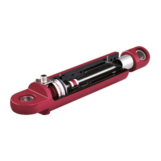
Temposonics MH Digital ® Operating Manual 1. Product description and technology Temposonics sensors can be used in versatile mobile machines without any restriction and replace contact-based linear sensors like poten- ® tiometers. Highly dynamic systems are controlled safely by means of Temposonics sensors, thus enhancing the productivity, availability and ®... -
Page 4: Temposonics ® Mh Series Digital
Temposonics MH Digital ® Operating Manual 2. Temposonics MH series digital ® Temposonics MH series sensors are designed for hydraulic cylinders. With the digital output configuration they are qualified to operate on ® electronic controls of mobile machines. Sensors with different bus protocols CANopen, CANopen Safety and SAE J 1939 are suitable for net- work applications on vehicles. - Page 5 Temposonics MH Digital ® Operating Manual and members of the personnel are not authorized to increase or change the warranty conditions. * Qualified personnel means persons who are: - familiar with the projection of safety concepts for automation equipment. - competent in the field of EMC. - have been trained adequately for commissioning and service work - familiarized with the operation of the equipment and know the information required for perfect operation given in the product documenta- tion.
-
Page 6: Electrical Connection
Temposonics MH Digital ® Operating Manual 4. Electrical connection Temposonics MH sensors are equipped with an M12 connector. For simple connection to a CAN bus, the connector pin allocation is in compli- ® ance with the CiA-DR 303-1 specification. Detailed information on the mechanical installation of the sensor into the mobile hydraulic cylinder is given in the instal- lation manual. -
Page 7: Order Of Connection
Temposonics MH Digital ® Operating Manual 4.2 Order of connection MH sensor with digital output Correct Connection 12 / 24 VDC 120 Ω Please pay attention to connecting sequence! Order Wire color Assignment 12 / 24 VDC CAN_Lo CAN_Hi VDC-GND 12 / 24 VDC 120 Ω... -
Page 8: Bus Termination / Network Connection
Temposonics MH Digital ® Operating Manual 4.3 Bus termination / Network connection In a 2-wire bus system like a CAN bus, serial data transmission is used, whereby the voltage difference between CAN_HI and CAN_LO is the bit information. To attenuate signal reflections at the open end of the bus, the data lines must be connected using a 120 Ω terminating resistor. The resistor should be inserted between the CAN_HI and CAN_LO data lines. -
Page 9: Connection In The Network
Temposonics MH Digital ® Operating Manual 4.4 Connection in the network Node ID: 01 12 / 24 VDC Node ID: 10 12 / 24 VDC 120 Ω Node ID: 7F 12 / 24 VDC Caution! Please pay attention to individual Node ID‘s in network. -
Page 10: Diagram For Connection To The Vehicle Electronics
Machine ground Cable shielding To ensure perfect operation of the sensor, the hydraulic cylinder must In the installed condition, the sensor is shielded sufficiently by the be connected to the machine ground. Equipotential bonding is often metal hydraulic cylinder. For this reason, no separate shielding is ensured by the mechanical contact between the cylinder and other taken via the M12 connector. - Page 11 +24 VDC GND (0V) 2 cable shield VDC (+) GND (-) RT= 120 Ω Chassis GND Power supply 1. Conductive metal Connector Housing Input Controller Cylinder to chassis earth- input filter of sensor become active. 2. Cable shield connected to chassis GND on both sides: Protection against electro-magnetic interference.
-
Page 12: Operation And Function
Temposonics MH Digital ® Operating Manual 5. Operation and function 5.1 Insulation checks Part of the testing performed on off-road mobile machinery can be insulation checks. During these checks, high voltages are applied to deter- mine the dielectric strength of the cables against the housing (insulation resistance). For testing, all connecting cables must be disconnected from the sensors. -
Page 13: What Should Be Done In The Event Of Functional Disorder
Temposonics MH Digital ® Operating Manual 6. What should be done in the event of functional disorder? 6.1 Typical installation faults and their consequences Cause Consequences Faulty pin allocation No signal Ambient temperature too high Component failure Component damage because the sensor has been hammered down too Cylinder borehole too small violently Component damage because the sensor has been hammered down too... -
Page 14: Can Bus Protocols
Temposonics MH Digital ® Operating Manual 7. CAN Bus protocols The ISO 11898 international standard CAN bus (Controller Area Network) is a machine level, open field bus for fast serial data transfer between a central process control system (master) and decentralized intelligent field instruments (slaves). Various protocols, which have been developed for a variety of applications and by different user groups can be used for data transfer. -
Page 15: Communication Objects
Temposonics MH Digital ® Operating Manual 9. Communication objects CANopen & CANopen Safety The information flow of function data and user-specific information is subject to a data protocol according to OSI model (ISO 7498). The CiA (CAN in Automation) user organization is in charge of the CAN bus technology and its further development. During the „operational“... -
Page 16: Starting The Operation
Temposonics MH Digital ® Operating Manual SAE J1939 SAE J1939 is provided with extended message arbitration. Compared to CANopen, the message identifier has been extended to 29 bits. Due to this protocol extension, different message prioritization and assignment of bus sharing units is implemented. For large quantities of data, in particular, utilization of a separate transport protocol is possible. - Page 17 Temposonics MH Digital ® Operating Manual Setting the Node ID A number (node ID) must be assigned to each node. The number is used for identification of the node in a CANopen network. Each individual node ID must be unique. The node ID CANopen is within a range of 1- 127, the node id CANopen Safety is within a range of 0 - 64, and can al- ready be preset when ordering.
- Page 18 Temposonics MH Digital ® Operating Manual Baud rate setting: Data source COB-ID Data Destination Controller 0x7e5 04; 01; 00; 00; 00; 00; 00; 00 Sensor CANopen Controller 0x7e5 13; 00; 02*; 00; 00; 00; 00; 00 Sensor Sensor 0x7e4 13; 00; 00; 00; 00; 00; 00; 00 Controller * Table Index After sending ,save network parameter’...
-
Page 19: System Start
Temposonics MH Digital ® Operating Manual 10.2 System start CANopen & CANopen Safety After configuration of the node parameters, the sensor can be integrated into the network. When switching on, or after reset, the sensor under- goes hardware initialization. During this procedure, all components are set into a defined initial state. Subsequently, the sensor loads the instru- ment and communication-specific parameters from an EEPROM and saves them for configuration. -
Page 20: Setting The Operating Parameters
Temposonics MH Digital ® Operating Manual 10.3 Setting the operating parameters CANopen & CANopen Safety At system start-up (power-on, reset), the sensor saves the operating parameters stored in the EEPROM. When switching on, these are the fac- tory-set parameters, or the data which has already been changed and saved. Changes are made e.g. via SDOs when the pre-operational mode is activated. -
Page 21: Sensor Data During Operation
Temposonics MH Digital ® Operating Manual SAE J1939 The SAE J1939 sensor operating parameters can be set analogously to the CANopen sensor. The sensor can receive configuration messages during operation and saves the settings immediately after receiving the message. The following operating parameters are configurable: Cycle Time (Transmission Repetition Rates) The transmission Repetition Rate (Update Rate) is the interval at which a new position value is available at the sensor output. -
Page 22: Error Messages (Emergency Object)
Temposonics MH Digital ® Operating Manual SAE J1939 For data output, the Temposonics MH series position sensor provides a Data Record Message. ® Identifier Error Limit 0x18 PFPSSA Position Speed Status 0xFF Code Status Fig. Allocation of parameter information to the PDU when using the default setting PF –... - Page 23 © 2021 Temposonics, LLC – all rights reserved. Temposonics, LLC and Temposonics GmbH & Co. KG are subsidiaries of Amphenol Corporation. Except for any third party marks for which attribution is provided herein, the company names and product names used in this document may be the registered trademarks or unregistered trademarks of Temposonics, LLC or...
Need help?
Do you have a question about the Temposonics MH Digital Series and is the answer not in the manual?
Questions and answers