Table of Contents
Advertisement
Quick Links
Temposonics
Absolute, Non-Contact Position Sensors
Operating Manual
MH Series - Temposonics
MH / MS / MT
Temposonics
Magnetostrictive Linear Position Sensors
®
MH Series
MH Analog
®
MH / MS / MT
Operating Manual
All specifications are subject to change. Contact MTS for specifications and engineering
drawings that are critical to your application. Drawings contained in this document are for
reference only.
Please visit www.mtssensor.com for the actual support documentation- related to your
selected model.
MH Analog
®
Document Part Number
551290 Revision B
Document Part No.
551290 Revision B
Advertisement
Table of Contents

Subscribe to Our Youtube Channel
Related Manuals for Amphenol Temposonics MH Series


Summary of Contents for Amphenol Temposonics MH Series
- Page 1 Temposonics ® Absolute, Non-Contact Position Sensors Operating Manual MH Series - Temposonics MH Analog ® MH Series MH / MS / MT Temposonics MH Analog ® Document Part Number 551290 Revision B MH / MS / MT Magnetostrictive Linear Position Sensors Document Part No.
-
Page 2: Table Of Contents
Contents 1. Product description and technology ................2. Temposonics MH series analog ...............4 ® 3. Safety and operating instructions ..............4 4. Electrical connection ..................6 4.1 Connecting diagrams, pin allocation, conductor colors .........6 4.2 Order of connection ..................9 - Correct connection ..................9 - Polarity protection VDC-GND ...............9 4.3 Diagram for connection to the vehicle electronics ........ -
Page 3: Product Description And Technology
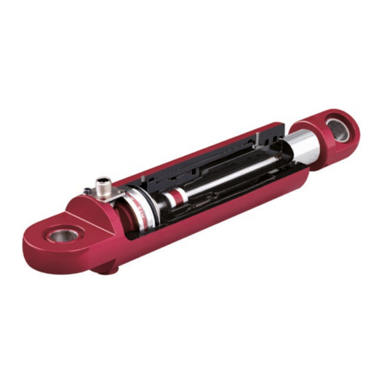
Temposonics MH Analog ® Operating Manual 1. Product description and technology Temposonics sensors can be used in versatile mobile machines without any restriction and replace contact-based linear sensors like poten- ® tiometers. Highly dynamic systems are controlled safely by means of Temposonics sensors, thus enhancing the productivity, availability and ®... -
Page 4: Temposonics ® Mh Series Analog
Temposonics MH Analog ® Operating Manual 2. Temposonics MH series analog ® Temposonics MH series sensors are designed for hydraulic cylinders. With the analog output configuration they are qualified to operate on ® electronic controls of mobile machines. Sensors with different analog output signals (mA/ VDC) are suitable for applications on vehicles. 3. - Page 5 Temposonics MH Analog ® Operating Manual * Qualified personnel means persons who are - familiar with the projection of safety concepts for automation equipment. - competent in the field of EMC. - have been trained adequately for commissioning and service work - familiarized with the operation of the equipment and know the information required for perfect operation given in the product documentation.
-
Page 6: Electrical Connection
Temposonics MH Analog ® Operating Manual 4. Electrical connection Temposonics MH series sensors are equipped with an M12 connector. For electrical wiring pin assignment has to be checked. Optionally, the ® sensors are available with single wire or PUR cable outlet. Please use suitable mating connectors. Detailed information relating to the mechanical installation of the sensor in the mobile hydraulic cylinder is given in the installation instructions. - Page 7 Temposonics MH Analog ® Operating Manual Type MS Analog Connector system M12 4 x 0,25 mm Pin assignment connector system M12 12/24 VDC GND (OV) Signal n.c. Top view: male pin connector Single wires 3 x 0,25 mm Wire assignment single wires Wire color 12/24 VDC GND (OV)
- Page 8 Temposonics MH Analog ® Operating Manual Type MT Analog Connector system M12 (2xM12x1) Connector 4 pin = (channel A (•)) and 5 pin = (channel B (••)) The channels are marked with dots on the housing. Channel A (•) 4 pin connector Channel B (• •) 5 pin connector 12/24 VDC 12/24 VDC GND (OV) GND (OV) Signal...
-
Page 9: Order Of Connection
Temposonics MH Analog ® Operating Manual 4.2 Order of connection MH sensors with analog output (VDC/mA) Correct connection 12/24 VDC Signal RL > 10 kΩ @ 12/24 VDC RL < 250 Ω @ 12VDC Please pay attention to connecting sequence! RL <... -
Page 10: Diagram For Connection To The Vehicle Electronics
Machine ground Cable shielding To ensure perfect operation of the sensor, the hydraulic cylinder must In the installed condition, the sensor is shielded sufficiently by the be connected to the machine ground. Equipotential bonding is often metal hydraulic cylinder. For this reason, no separate shielding is ensured by the mechanical contact between the cylinder and other taken via the M12 connector. - Page 11 +12 / 24 VDC GND (0V) Signal 2 cable shield — VDC (+) GND (-) RL= 500 Ω (24 VDC) Chassis GND Power supply 250 Ω (12 VDC) 1. Conductive metal Connector Housing Cylinder to chassis earth- input filter of sensor become active 2.
-
Page 12: Operation And Function
Temposonics MH Analog ® Operating Manual 5. Operation and function 5.1 Filter circuitry (noise) Any resistor causes for example thermal noise, which is more or less evident at the output of the circuitry if amplified accordingly. Additionally, external effects such as the supply voltage ripple or electro-magnetic fields in the immediate vicinity can affect the noise spectrum. To minimize noise, the use of a filter is mandatory with analog measurement. -
Page 13: Set Point Tolerance Zero To Full Scale
Temposonics MH Analog ® Operating Manual 5.2 Set point tolerance zero to full scale At MTS, the sensor set points are calibrated with a tolerance of ± 1 mm. When installing in cylinders, please note that any additional tolerances must be taken into account. During teach-in, all tolerances in the cylinder-and-sensor system are eliminated. The piston rod drives towards the zero or full scale. -
Page 14: Insulation Checks
Temposonics MH Analog ® Operating Manual 5.3 Insulation checks Part of the testing performed on off-road mobile machinery can be insulation checks. During these checks, high voltages are applied to deter- mine the dielectric strength of the cables against the housing (insulation resistance). For testing, all connecting cables must be disconnected from the sensors. -
Page 15: What Should Be Done In The Event Of Functional Disorder
Temposonics MH Analog ® Operating Manual 6. What should be done in the event of functional disorder? 6.1 Typical installation faults/consequences Cause Consequences Faulty pin allocation No signal Ambient temperature too high Possible damage to components – no sensor signal Component damage, because the sensor has been hammered Cylinder borehole too small down too violently. -
Page 16: Checking The Sensor Function
Temposonics MH Analog ® Operating Manual 6.2 Checking the sensor function Analog sensors (current or voltage output and PWM) • Check the connections and the pin allocation • Check the supply voltage • Disconnect the sensor and test it in connection with an external power supply (e.g. car battery) • Use a Temposonics test unit. The operating instructions of the test unit are ® available for downloading from the log-in area under www.mtssensor.com • Use the multimeter in accordance with the explanation. - Page 17 Temposonics MH Analog ® Operating Manual Measuring the VDC output signal Use a multimeter and select the VDC multimeter measuring range to measure the output signal (0.25 – 4.75 VDC; 0.5 – 4.5 VDC and 0.5 – 9.5 VDC). Connect the multimeter with the green signal conductor and the white 0 V conductor. Connect the supply voltage (+12/24 VDC) to the brown conductor and O V (-0 V) to the white conductor.
- Page 18 © 2021 Temposonics, LLC – all rights reserved. Temposonics, LLC and Temposonics GmbH & Co. KG are subsidiaries of Amphenol Corporation. Except for any third party marks for which attribution is provided herein, the company names and product names used in this document may be the registered trademarks or unregistered trademarks of Temposonics, LLC or...
Need help?
Do you have a question about the Temposonics MH Series and is the answer not in the manual?
Questions and answers