
Related Manuals for MRC FH-12-DB


Summary of Contents for MRC FH-12-DB
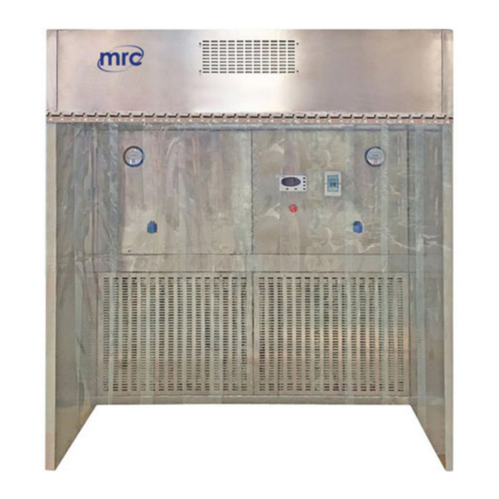
- Page 1 Dispensing Booth FH-12/18/24-DB User Manual 3, Hagavish st. Israel 58817 Tel: 972 3 5595252, Fax: 972 3 5594529 mrc@mrclab.com MRC. 10.22...
-
Page 2: Table Of Contents
Content Content..............................1 Foreword..............................2 1. Unpacking, Installation and Commissioning..................3 1.1 Unpacking..........................3 1.2 Accessories Check........................4 1.3 Precautions before Installation....................7 1.4 Machine Installation Placement and Use Environment............7 1.5 Installation..........................7 2. Instructions for Use.......................... 15 2.1 Function...........................15 2.1.1 Product Concept...................... -
Page 3: Foreword
Foreword Dear respected user Welcome to select and purchase MRC dispensing booth series, here please accept our sincere thanks We sincerely hope that our products can bring the greatest help for your work ● For the first time to use the product, please read this manual carefully! ●... -
Page 4: Unpacking, Installation And Commissioning
1. Unpacking, Installation and Commissioning Please check whether the outer box is intact, if not, please take pictures. 1.1 Unpacking Program I. Disassembled with a wrench Figure 1 Program II. Disassembled with an electric drill Figure 2 Quick unpacking diagram (Remove the screws, as are shown below, and then take the wooden box to the left.)... -
Page 5: Accessories Check
Figure 3 1.2 Accessories Check Please refer to the packing list, carefully check whether the accessories and information are complete. FH-12-DB Packing List Item Quantity Position Main Body Power Cord Fuse (5A) Fuse (10A) UV Lamp (T8 30W) Anti-static Curtain... - Page 6 FH-18-DB Packing List Item Quantity Position Rear Cabinet, Left and Right Side Panels Power Cord Fuse(5A) Fuse(10A) UV Lamp(T8 40W) User Manual 1copy Test Report 1 copy Quality Certification Card Wooden Package 1 Warranty Card Accessory Box 304 Cross Recessed Pocket Hexagon Head Combination Screw with Flat 12 sets Gasket and Spring Gasket M4 * 30...
- Page 7 FH-24-DB Packing List Item Quantity Position Rear Cabinet, Left and Right Side Panels Power Cord Fuse(5A) Fuse(10A) UV Lamp(T8 30W) 2pcs User Manual 1copy Test Report 1 copy Quality Certification Card Wooden Package 1 Warranty Card Accessory Box 304 Cross Recessed Pocket Hexagon Head Combination Screw with Flat 12 sets Gasket and Spring Gasket M4 * 30...
-
Page 8: Precautions Before Installation
1.3 Precautions before Installation Please note the following points: • Please choose the ground, wall structure which can withstand the weight of the equipment, the plane of the installation site should be flat. • The equipment is prohibited to use in the following places: dust, oil mist, chemical corrosion and other harsh places. - Page 9 (as is shown Figure 4 ). Note: The rear cabinet of FH-12-DB, FH-18-DB dispensing booth has two rear panels, and the rear cabinet of FH-24-DB dispensing booth has one rear panel, and the remove method is the same with...
- Page 10 Left Side Panel Rear Cabinet Insert the M10*25 bolt into thecorresponding mounting The back of the hole bolt is fixed with a nut Positioning bolt Partial enlarged drawing Figure 5 Take the left side panel, and insert the M10 * 25 bolt on the left side panel into the rear cabinet mounting hole (as is indicated by the arrow) and fix it with 3 groups of flat gaskets 10 + spring gaskets 10 + 3 sets M10 hex nuts, and fasten it withNo.17 wrench, the two positioning M10 * 25 bolts at the bottom side play the role of positioning, which do not need nuts for fastening,The top is...
- Page 11 The installation steps for connecting the upper front cabinet with the rear cabinet are as (2) follows: Figure6 Take the upper front cabinet, and place the upper front cabinet on the left and right side panels (as is indicated by the arrow) so that the mounting holes of the upper front cabinet are matched with the M10 * 25 bolts on the left and right side panels, meanwhile making the upper front cabinet is aligned with the mounting hole on the rear cabinet,the left and right side of the upper front cabinet are flush with the left and right side panels and fix with 8 groups of flat gaskets 10 + spring gaskets...
- Page 12 Take the upper rear cabinet, remove the 304 cross recessed pocket hexagon head combination screw with flat gasket and spring gasket M4*12 with a flat-blade screwdriver, remove the upper rear cover panel( as is shown in Figure 7) Figure8 As is shown in the figure, install the upper rear cabinet on the rear cabinet, making the mounting holes of upper rear cabinet be aligned with the mounting holes of upper front cabinet and rear cabinet.
- Page 13 Lighting, trachea, wire harness connection (4) LED fluorescent tube LED fluorescent tube coatsilver gray glue on the UV light connection part of the upper rear cabinet and the rear cabinet Figure9 In the operating area, coat silver gray glue on the connection part of the upper rear cabinet and the rear cabinet, to avoid the gas in the rear cabinet enter into the operating area.
- Page 14 connect the fan line with the wire harness in the rear cabinet, the connection is completed. Plug the power cord, close the air switch, turn the emergency switch in the direction of the arrow, press the power button, press the fan button to check whether the fan runs properly.If not, please refer to 3.1 to conduct troubleshooting.
- Page 15 Firstly, remove the 304 cross recessed pocket hexagon head combination screw with flat gasket and spring gasket M4 * 12 with a flat-blade screwdriver, remove the outer row cover panel. Take the anti-static curtain, hang the curtain on the keel (as is shown in Figure 12), the installation will be completed outside the cover plate can be restored.
-
Page 16: Instructions For Use
2. Instructions for Use 2.1 Function 2.1.1 Product Concept The dispensing booth is a local purification equipment dedicated to places such as pharmaceuticals, microbiological research and scientific experiments. It provides a kind of vertical, unidirectional airflow that produces negative pressure in the working area, part of the clean air circulates in the working area, part is discharged to the nearby area to prevent cross-contamination, to ensure the high cleanliness in the working area. -
Page 17: Technical Parameters Performance Indicators
The net amplitude of vibration between 10 Hz and 10 kHz does not exceed 5 μm (rms). 2)Illuminance The average illuminance is greater than or equal to 500 lx. 3)Electrical performance 1390V within 5s, to break down within 5s is impossible. Grounding resistance: ≤ 0.1Ω. Product Structure 2.2 The structure of FH-12-DB/FH-18-DB/FH-24-DB dispensing booth consists of... - Page 18 Figure14 1. Upper rear cabinet 2. Upper front cabinet 3. Upper cabinet 4. Side panel 5. Control panel 6. Emergency switch 7. Waterproof socket8. Air switch 9. Differential pressure gauge10. UV lamp 2.2.1 Structure composition A. Structure Dispensing booth adopts modular design, on-site assembly and disassembly is convenient. Equipment is assembled from the working area, upper front cabinet, upper rear cabinet, rear cabinet and the side panel.
- Page 19 The UV lamp is located on the underside of the homogeneous film to ensure that the UV light is fully exposed to all space in the operating area. UV lamp has a delayed opening function, press the UV light button, the operator quickly evacuate the scene, after 90S UV lamp is light to protect the eyes and skin, and avoid injury caused byaccidental exposure.
- Page 20 (6) “ ”Is the UV lamp timing increase button, shut down the fun, turn off the fluorescent lamp under the display state of the display screen, press the button, the display screen will display the timing time of the UV lamp. After each press, the buzzer will ring once, and the set time will increase one minute.
-
Page 21: Precautions For Use
If abnormal noise, odor, smoke, etc. occur during use, disconnect the power supply immediately. Users should not blindly hands-on repair, but notify MRC maintenance department or local special maintenance point, and the equipment should be checked, repaired by the professional technical... -
Page 22: Storage Conditions
pressure, please replace or clean the filter) according to the cleanliness of the environment. Regularly (usually once every two months) with the dust particle counter to determine the cleanliness of area being purified by the product, when the measured cleanliness is inconsistent with the required cleanliness, reason should be identified (whether there is leakage, whether the high efficiency filter has a failure etc.), if the high efficiency filter has failure, please replace a new high efficiency filter. -
Page 23: Replacement Parts List
2.6 Replacement Parts List FH-12-DB Replacement Parts List Name Specification DB-01 Protective Tube DB-02 Protective Tube DB-03 UV lamp T8 30W LED fluorescent DB-04 T5 14W lamp (whole) UV disinfection DB-05 T8 30W lamp holder DB-07 SC355A 1 set of control... - Page 24 FH-24-DB Replacement Parts List Name Specification DD-01 Protective Tube DD-02 Protective Tube DD-03 UV lamp T8 30W LED fluorescent lamp DD-04 4*16W/2*14W (whole) disinfection lamp DD-05 T8 30W holder DD-06 SC400A DD-07 1 set of control panel Control panel of the dispensing booth...
-
Page 25: Common Fault Analysis And Solution
3. Common Fault Analysis and Solution 3.1 Common Fault Analysis Before diagnosing the fault, please make sure whether the power supply is connected well, whether the power cord is obviously damaged, and the protective tube is good. 1、Check whether the equipment is grounded reliably in accordance with the requirements of the instructions, to ensure the security of maintenance and use. -
Page 26: Method For Replacing Simple Parts
Protective tube Whether the protective tube is good Transformer Whether the transformer output is normal Control panel Replace the control panel Connecting cable Check whether the connecting cable is connected well The display screen Display screen Check whether the display screen is does not light good Control panel... -
Page 27: Replace The Uv Lamp
When the equipment has a failure which is not listed above, and the operator can not immediately rule out, please immediately notify MRC maintenance department, for your safety, please do not repair equipment by yourself... -
Page 28: Warranty
If the failure or damage of the instrument and equipment in the warranty period is caused by user’s improper use, MRC does not undertake maintenance obligations After the warranty period, MRC is responsible for maintenance, and charges the corresponding maintenance costs... -
Page 29: Appendix A Circuit Diagram
5. Appendix A Circuit diagram...
Need help?
Do you have a question about the FH-12-DB and is the answer not in the manual?
Questions and answers