YASKAWA MP2000 Series User Manual
Ethernet/ip communication module.
machine controller
Hide thumbs
Also See for MP2000 Series:
- User manual (557 pages) ,
- Troubleshooting manual (60 pages) ,
- Technical note (55 pages)
Table of Contents
Advertisement
Quick Links
Download this manual
See also:
User Manual
Machine Controller MP2000 Series
263IF-01
EtherNet/IP Communication Module
USER'S MANUAL
Model: JAPMC-CM2304-E
263IF-01
MS
TX
INIT
TEST
LINK
100M
MANUAL NO. SIEP C880700 39A
NS
IP
RX
NO
OFF
ON
EtherNet/IP
Explicit Message and Explicit Message Send Function
EtherNet/IP Communication
263IF-01 Module
Mounting and Starting the Module
EtherNet/IP Transmission Definition
Troubleshooting
Appendices
1
2
3
4
5
6
App
Advertisement
Table of Contents

Related Manuals for YASKAWA MP2000 Series


Summary of Contents for YASKAWA MP2000 Series
- Page 1 Machine Controller MP2000 Series 263IF-01 EtherNet/IP Communication Module USER’S MANUAL Model: JAPMC-CM2304-E 263IF-01 INIT TEST EtherNet/IP EtherNet/IP Communication LINK 263IF-01 Module 100M Mounting and Starting the Module EtherNet/IP Transmission Definition Explicit Message and Explicit Message Send Function Troubleshooting Appendices MANUAL NO. SIEP C880700 39A...
- Page 2 Yaskawa. No patent liability is assumed with respect to the use of the information contained herein. Moreover, because Yaskawa is constantly striving to improve its high-quality products, the information contained in this manual is subject to change without notice.
- Page 3 Using this Manual This manual describes EtherNet/IP Communication Module 263IF-01 for the MP2000-series Machine Controller. Read this manual thoroughly before using the 263IF-01. Keep this manual in a safe place for future reference. Basic Terms Unless otherwise specified, the following definitions are used: •...
- Page 4 Series Machine Controller built-in SVB Module User’s Manual and slot-mounting optional SVB-01 Module. Provides the information on the Communication Machine Controller MP2000 Series Module that can be connected to MP2000 Series SIEP C880700 04 Communication Module User’s Manual Machine Controller and the communication meth- ods.
- Page 5 Safety Information The following conventions are used to indicate precautions in this manual. Information marked as shown below is important for the safety of the user. Always read this information and heed the precautions that are provided. The con- ventions are as follows: Indicates precautions that, if not heeded, could possibly result in loss of life or serious WARNING injury.
- Page 6 Storage and Transportation CAUTION Do not store or install the product in locations subject to the following. There is a risk of fire, electric shock, and machine product damage. Direct sunlight Ambient temperatures exceeding the storage or operating conditions ...
- Page 7 Wiring CAUTION Check the wiring to be sure it has been performed correctly. There is a risk of motor run-away, injury, or an accident. Always use a power supply of the specified voltage. There is a risk of burning. ...
- Page 8 The drawings presented in this manual are typical examples and may not match the product you received. If the manual must be ordered due to loss or damage, inform your nearest Yaskawa representative or one of the offices listed on the back of this manual.
- Page 9 6. Events for which Yaskawa is not responsible, such as natural or human-made disasters ( 2 ) Limitations of Liability 1. Yaskawa shall in no event be responsible for any damage or loss of opportunity to the customer that arises due to failure of the delivered product.
- Page 10 1. It is the customer’s responsibility to confirm conformity with any standards, codes, or regulations that apply if the Yaskawa product is used in combination with any other products. 2. The customer must confirm that the Yaskawa product is suitable for the systems, machines, and equipment used by the customer.
-
Page 11: Table Of Contents
Contents Using this Manual - - - - - - - - - - - - - - - - - - - - - - - - - - - - - - - - - - - - - - - - - - - - - - - - - - - - - - - iii Safety Information - - - - - - - - - - - - - - - - - - - - - - - - - - - - - - - - - - - - - - - - - - - - - - - - - - - - - - - v Safety Precautions - - - - - - - - - - - - - - - - - - - - - - - - - - - - - - - - - - - - - - - - - - - - - - - - - - - - - - v Warranty - - - - - - - - - - - - - - - - - - - - - - - - - - - - - - - - - - - - - - - - - - - - - - - - - - - - - - - - - - - - - ix... - Page 12 4 EtherNet/IP Transmission Definition - - - - - - - - - - - - - - - - - - - - - - - - - - - - - - 4-1 4.1 Displaying the EtherNet/IP Transmission Configuration Window - - - - - - - - - - - - 4-2 4.1.1 Displaying the Module Configuration Window - - - - - - - - - - - - - - - - - - - - - - - - - - - - - - - - - - 4-2 4.1.2 Displaying the EtherNet/IP Transmission Configuration Window from the Module Configuration Window - - - - - - - - - - - - - - - - - - - - - - - - - - - - - - - - - - - - - - 4-3...
-
Page 13: Ethernet/Ip Communication
EtherNet/IP Communication This chapter gives an overview of EtherNet/IP communication. 1.1 What is EtherNet/IP? - - - - - - - - - - - - - - - - - - - - - - - - - - - - - - - - - - - - - -1-2 1.2 EtherNet/IP Features - - - - - - - - - - - - - - - - - - - - - - - - - - - - - - - - - - - - - -1-3 1.3 EtherNet/IP (CIP) Communication Types - - - - - - - - - - - - - - - - - - - - - - - -1-4 1.3.1 Explicit Message Communication - - - - - - - - - - - - - - - - - - - - - - - - - - - - - - - - - - - - - - 1-4... -
Page 14: What Is Ethernet/Ip
1.1 What is EtherNet/IP? 1.1 What is EtherNet/IP? EtherNet/IP is a standard network in which the CIP (Common Industrial Protocol), defined by EN50170 and IEC61158 standards and proven in DeviceNet, is implemented over standard Ethernet and TCP/IP protocols. EtherNet/IP can handle the I/O messages that are used to control devices or to perform interlock communication between the controllers in real time, and also the explicit messages that check the configuration of and diagnose field devices. -
Page 15: Ethernet/Ip Features
1.2 EtherNet/IP Features 1.2 EtherNet/IP Features EtherNet/IP is a standard network configured with standard worldwide protocols (Ethernet, TCP/IP, and CIP), it has the following features since it uses standard protocols. • Can manage and integrate entire production systems, from field devices to the internet. •... -
Page 16: Ethernet/Ip (Cip) Communication Types
1.3 EtherNet/IP (CIP) Communication Types 1.3.1 Explicit Message Communication 1.3 EtherNet/IP (CIP) Communication Types There are two kinds of CIP communication: Explicit message communication and I/O communication. 1.3.1 Explicit Message Communication Explicit messages are used in general message communication between the client and the server (peer-to-peer commu- nication). -
Page 17: 263If-01 Module
263IF-01 Module This chapter describes the external appearance and specifications of the 263IF-01 Module. 2.1 Features - - - - - - - - - - - - - - - - - - - - - - - - - - - - - - - - - - - - - - - - - - - - - - -2-2 2.1.1 I/O Communication - - - - - - - - - - - - - - - - - - - - - - - - - - - - - - - - - - - - - - - - - - - - - - - - 2-2 2.1.2 Explicit Message Communication - - - - - - - - - - - - - - - - - - - - - - - - - - - - - - - - - - - - - - 2-3 2.1.3 Engineering Communication - - - - - - - - - - - - - - - - - - - - - - - - - - - - - - - - - - - - - - - - - - 2-4... -
Page 18: Features
2.1 Features 2.1.1 I/O Communication 2.1 Features A 263IF-01 Module can perform I/O communication, explicit message communication and engineering communica- tion. 2.1.1 I/O Communication In I/O communication (Class 1), communication of time-critical control data is possible. This type of communication is mainly used between scanners and adaptors in a 1:1 or 1:N configuration. -
Page 19: Explicit Message Communication
2.1 Features 2.1.2 Explicit Message Communication 2.1.2 Explicit Message Communication In explicit message communication, general message communication is possible. In explicit message communication using the 263IF-01 Module, the Module provides both the client (UCMM) and server (Class 3, UCMM) functions, and is mainly used in communication between the client and server (maximum number of connected devices = 64) in 1:1 (peer-to-peer) configuration. -
Page 20: Engineering Communication
2.1 Features 2.1.3 Engineering Communication 2.1.3 Engineering Communication By connecting the 263IF-01 Module to the Programming Device MPE720, ladder programming and monitoring are possible through engineering communication. The self configuration function of the MP2000-series Machine Controller enables an Ethernet connection between the personal computer where MPE720 is installed and the 263IF-01 Module, without requiring settings for connections at the 263IF-01 Module. -
Page 21: Specifications
2.2 Specifications 2.2.1 Hardware Specifications 2.2 Specifications This section provides specifications for the 263IF-01 Module. 2.2.1 Hardware Specifications Item Specification Name 263IF-01 Model JAPMC-CM2304-E Communication Port EtherNet/IP: 1 port Module status indicators LED (red/green) (red/green) (green) (green) Indicators (green) EtherNet/IP status indicator LED LINK (yellow) 100M (green/orange) INIT... -
Page 22: Transmission Specifications
2.2 Specifications 2.2.2 Transmission Specifications 2.2.2 Transmission Specifications Item Specifications 100BASE-TX 10BASE-T Interface RJ-45 connector Compliance Standard IEEE802.3u IEEE802.3i Media Access Mode CSMA/CD Communication Mode Full duplex/half duplex Modulation Method Baseband Topology Communication Protocol TCP/UDP/IP/ICMP/IGMP Baud Rate 100 Mbps 10 Mbps Maximum Number of Ethernet 2 levels... - Page 23 2.2 Specifications 2.2.2 Transmission Specifications Item Specifications Max. Number of Connectable Devices for 64 units Explicit Message (Number of devices that can communicate simultaneously: 10) Communication Number of Message Channels Explicit Max. Number of Message 504 bytes Message Bytes Specifications Function for Execution MSG-SND Function Communication Mode...
-
Page 24: Software Configuration
2.2 Specifications 2.2.3 Software Configuration 2.2.3 Software Configuration The following figure illustrates the software configuration that provides the 263IF-01 Module functions. CPU Module Application layer Host interface Presentation layer Session layer Scanner/adaptor function Engineering tool interface EtherNet/IP communication protocol Transport layer TCP/UDP Network layer ARP/IP/ICMP/IGMP... -
Page 25: Operating Environment Specifications
2.2 Specifications 2.2.4 Operating Environment Specifications 2.2.4 Operating Environment Specifications Item Specifications Ambient 0 to +55 °C Operating Temperature Ambient Storage -25 to +85°C Temperature Ambient Operating 30% to 95% RH (with no condensation) Environmental Humidity Conditions Ambient Storage 5% to 95% RH (with no condensation) Humidity Pollution Level Pollution level: 2 (conforming to JIS B3502) -
Page 26: Overview
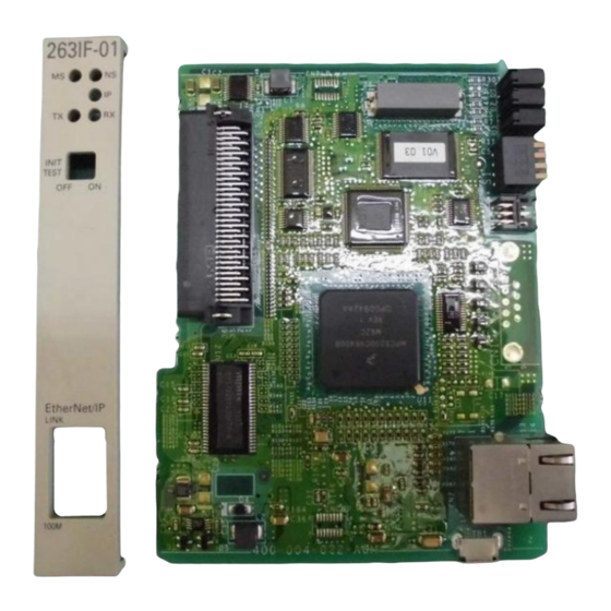
2.3 Overview 2.3.1 Appearance and Connectors 2.3 Overview 2.3.1 Appearance and Connectors The following illustration shows the appearance of the 263IF-01 Module and provides the external dimensions of the connector. (25 mm) Status indicators (LEDs) 263IF-01 Switches INIT TEST EtherNet/IP connector EtherNet/IP 100Base-TX/10Base-T LINK... -
Page 27: Communication Status Indicators (Leds) (Contained In The Ethernet Connector)
2.3 Overview 2.3.3 Communication Status Indicators (LEDs) (Contained in the Ethernet Connector) 2.3.3 Communication Status Indicators (LEDs) (Contained in the Ethernet Connector) The indicators (LEDs) contained in the EtherNet/IP connector indicate the status of EtherNet/IP communication. Indicator Color Meaning When Lit Meaning When Not Lit LINK Yellow... -
Page 28: Connection Specifications
– – – – – 2.4.2 Cable Specifications Yaskawa does not provide EtherNet/IP cables. Obtain commercially available category 5 cross or straight cables. The AUTO MDI/MDI-X function of the 263IF-01 Module automatically distinguishes between cross and straight cables. 2-12... -
Page 29: Mounting And Starting The Module
Mounting and Starting the Module This chapter describes how to connect the 263IF-01 Module and start the system, focusing on mounting the 263IF-01 Module, communication process setting, and self-configuration. 3.1 Applicable Machine Controllers and Supported Versions - - - - - - - - - - - - -3-2 3.1.1 Applicable Machine Controllers - - - - - - - - - - - - - - - - - - - - - - - - - - - - - - - - - - - - - - - - 3-2 3.2 Mounting and Removing a Module on the Machine Controller - - - - - - - - - -3-3 3.2.1 Mounting a 263IF-01 Module - - - - - - - - - - - - - - - - - - - - - - - - - - - - - - - - - - - - - - - - - 3-3... -
Page 30: Applicable Machine Controllers And Supported Versions
3.1 Applicable Machine Controllers and Supported Versions 3.1.1 Applicable Machine Controllers 3.1 Applicable Machine Controllers and Supported Versions 3.1.1 Applicable Machine Controllers The MP2000-series Machine Controllers to which the 263IF-01 Modules can be mounted are listed in the following table. Max. -
Page 31: Mounting And Removing A Module On The Machine Controller
3.2 Mounting and Removing a Module on the Machine Controller 3.2.1 Mounting a 263IF-01 Module 3.2 Mounting and Removing a Module on the Machine Controller This section explains the procedure for mounting and removing a 263IF-01 Module. 3.2.1 Mounting a 263IF-01 Module Use the following procedure to mount a 263IF-01 Module. - Page 32 3.2 Mounting and Removing a Module on the Machine Controller 3.2.1 Mounting a 263IF-01 Module Remove the Option Cover. Hold the battery cover with the front facing forward, insert the protrusion on the battery cover into the notch at the top of the Option Cover, and release the hook on the Option Cover. Release the hook on the bottom in the same way and remove the Option Cover.
- Page 33 3.2 Mounting and Removing a Module on the Machine Controller 3.2.1 Mounting a 263IF-01 Module ( 4 ) After Mounting the Module Connect to the Hub. Connect the 263IF-01 Module and the hub using the Ethernet cable. Refer to 2.4.2 Cable Specifications on page 2-12 for cables that can be used. Create Module Configuration Definitions.
-
Page 34: Removing A 263If-01 Module
3.2 Mounting and Removing a Module on the Machine Controller 3.2.2 Removing a 263IF-01 Module 3.2.2 Removing a 263IF-01 Module Use the following procedure to remove a 263IF-01 Module. ( 1 ) Preparation Backup the Programs. Save the programs written to the Machine Controller in the personal computer using MPE720. ... - Page 35 3.2 Mounting and Removing a Module on the Machine Controller 3.2.2 Removing a 263IF-01 Module Remove the 263IF-01 Module from the Mounting Base. Pull the top of the option panel to remove it. A notch can be seen in the 263IF-01 Module from the gap in the panel.
-
Page 36: Setting The Communication Manager
3.3 Setting the Communication Manager 3.3.1 Preparation of the Personal Computer 3.3 Setting the Communication Manager This section describes the software called the Communication Manager that is used to set the communication method for engineering communication between the personal computer running the MPE720 and the MP2000-series Machine Controller. - Page 37 3.3 Setting the Communication Manager 3.3.1 Preparation of the Personal Computer Check that the Automatically detect settings check box is cleared, and click the OK button to close the dialog box. For a computer running Windows 2000, click the Windows Start button and select Settings - Control Panel - Network and Dial-up Connections.
-
Page 38: Setting The Communication Manager
3.3 Setting the Communication Manager 3.3.2 Setting the Communication Manager Select Use the following IP address and enter “192.168.1.2” for IP address and “255.255.255.0” for Subnet mask. Then click the OK button to close the dialog box. 3.3.2 Setting the Communication Manager ( 1 ) Opening the Communication Manager Double-click the Communication Manager icon in the YE_Applications folder on the desktop to start the Communication Manager. - Page 39 3.3 Setting the Communication Manager 3.3.2 Setting the Communication Manager ( 2 ) Setting the Ethernet Communication Port In the Communication Manager window, double-click the number in the Logical PT column of a line which has not been set (In the following example, Line 2 and subsequent lines have not been set.) to view the Logical Port Setting dialog box.
- Page 40 3.3 Setting the Communication Manager 3.3.2 Setting the Communication Manager Save the settings and restart the Communication Manager. Refer to 3.3.2 ( 4 ) Saving the Communication Port Settings and Restarting the Communication Manager on page 3-13 for the procedure. ( 3 ) Setting the Ethernet (LP) Communication Port These settings are optimum for performing engineering via the Ethernet communication port of the 263IF-01 Module.
- Page 41 3.3 Setting the Communication Manager 3.3.2 Setting the Communication Manager Click the OK button in the Logical Port Setting dialog box. The display will return to the Communica- tion Manager window. Confirm that Ethernet (LP) is allocated to the selected Logical Port number. Save the settings and restart the Communication Manager.
-
Page 42: Self-Configuration
3.4 Self-configuration 3.4.1 Executing Self-configuration 3.4 Self-configuration The self-configuration function automatically detects the Option Modules connected to the Machine Controller and automatically generates the files for the Module configuration definitions and the detailed definition of each Module. Executing self-configuration will greatly reduce the system startup procedure. ... -
Page 43: Starting The Mpe720, And Setting Communication Or Network Parameters
3.5 Starting the MPE720, and Setting Communication or Network Parameters 3.5.1 Starting MPE720 Ver. 6 and Setting Communication Parameters 3.5 Starting the MPE720, and Setting Communication or Network Parameters This section describes how to start the MPE720, and how to set the communication parameters in the object file (MPE720 Ver. -
Page 44: Starting Mpe720 Ver. 5.Xx And Setting Network Parameters
3.5 Starting the MPE720, and Setting Communication or Network Parameters 3.5.2 Starting MPE720 Ver. 5.xx and Setting Network Parameters 3.5.2 Starting MPE720 Ver. 5.xx and Setting Network Parameters This section describes how to start the MPE720 and set the network parameters in the PLC folder. ... - Page 45 3.5 Starting the MPE720, and Setting Communication or Network Parameters 3.5.2 Starting MPE720 Ver. 5.xx and Setting Network Parameters Click the Network tab and select Yes for OnLine. Fields will be displayed for the logical port number, unit number, and route so that they can be set. For Logical Port No.
- Page 46 3.5 Starting the MPE720, and Setting Communication or Network Parameters 3.5.2 Starting MPE720 Ver. 5.xx and Setting Network Parameters A confirmation dialog box will be displayed. Click the Yes button. This completes selecting the logical port. Be sure to continue the setting of the transmission definition for the 263IF-01 Module. For details of the transmission definition setting, refer to Chapter 4 EtherNet/IP Transmission Definition.
-
Page 47: Ethernet/Ip Transmission Definition
EtherNet/IP Transmission Definition To perform EtherNet/IP communication with the 263IF-01 using an MP2000-series Machine Con- troller, an EtherNet/IP transmission definition file must be created. This chapter describes how to set the EtherNet/IP transmission definition on the MPE720 screen. 4.1 Displaying the EtherNet/IP Transmission Configuration Window - - - - - - - -4-2 4.1.1 Displaying the Module Configuration Window - - - - - - - - - - - - - - - - - - - - - - - - - - - - - - 4-2 4.1.2 Displaying the EtherNet/IP Transmission Configuration Window from the Module Configuration Window - - - - - - - - - - - - - - - - - - - - - - - - - - - - - - - - - - - - - 4-3... -
Page 48: Displaying The Ethernet/Ip Transmission Configuration Window
4.1 Displaying the EtherNet/IP Transmission Configuration Window 4.1.1 Displaying the Module Configuration Window 4.1 Displaying the EtherNet/IP Transmission Configuration Window This section describes how to open the Module Configuration window from the MPE720, open the EtherNet/IP Transmission Configuration window from the Module Configuration window, and set the transmission definition for the EtherNet/IP Module. -
Page 49: Displaying The Ethernet/Ip Transmission Configuration Window From The Module Configuration Window
4.1 Displaying the EtherNet/IP Transmission Configuration Window 4.1.2 Displaying the EtherNet/IP Transmission Configuration Window from the Module Configuration Window 4.1.2 Displaying the EtherNet/IP Transmission Configuration Window from the Module Configuration Window As the result of executing self-configuration, all Option Modules connected to the Machine Controller will be dis- played in the Controller area of the Module Configuration window. -
Page 50: Ethernet/Ip Transmission Definition
4.2 EtherNet/IP Transmission Definition 4.2.1 Network Parameter Tab Page 4.2 EtherNet/IP Transmission Definition The EtherNet/IP Transmission Configuration window has four tab pages, namely Network Parameters, Connection List, I/O Status and Module Information. Select the appropriate tab page to perform setting and monitoring. 4.2.1 Network Parameter Tab Page On the Network Parameter tab page, set the network parameters required to perform EtherNet/IP communication. - Page 51 4.2 EtherNet/IP Transmission Definition 4.2.1 Network Parameter Tab Page Gateway IP Address When communication is performed with other networks connected through a gateway (router), enter the IP address of the gateway. If there is no gateway or a gateway is not used, enter 0 for fields No. 1 to No. 4 of the gateway IP address. The data input range for the gateway IP address varies according to the field.
-
Page 52: Connection List Tab Page
4.2 EtherNet/IP Transmission Definition 4.2.2 Connection List Tab Page 4.2.2 Connection List Tab Page ( 1 ) Details of the Connection List Tab Page Make a list of devices connected to the EtherNet/IP on the Connection List tab page. The IP address of the device that is assigned to the list as a scanner must be identical to the IP address actually set for that device. - Page 53 4.2 EtherNet/IP Transmission Definition 4.2.2 Connection List Tab Page I/O Communication Setting – Input Setting Set whether the controller CPU exchanges the input data with the EtherNet/IP. When a checkmark is entered, data exchange is not performed. Instance No. [IN] Set an input instance number in the following range.
- Page 54 4.2 EtherNet/IP Transmission Definition 4.2.2 Connection List Tab Page Setting (Detail) button When Scanner is selected, clicking this button will open the IO Communication Detail Setting window where I/O communication details are set for the selected device. When Adaptor is selected, the IO Communication Detail Setting window is not displayed even if this button is clicked.
- Page 55 4.2 EtherNet/IP Transmission Definition 4.2.2 Connection List Tab Page Select Edit - Assignment Delete from the Main Menu. The assignment of the selected device is deleted and the line is left blank.
-
Page 56: Io Communication Detail Setting Window
4.2 EtherNet/IP Transmission Definition 4.2.3 IO Communication Detail Setting Window 4.2.3 IO Communication Detail Setting Window The IO Communication Detail Setting window opens when the Setting button of Scanner is clicked on the Connec- tion List tab page. If Adaptor is selected, this window does not open even if the Setting button is clicked. The following explains the details of the IO Communication Detail Setting window and the setting details. -
Page 57: Network Configuration Search Window
4.2 EtherNet/IP Transmission Definition 4.2.4 NetWork Configuration Search Window A switching hub delay of 1 ms to 10 ms can occur, depending on the number of connected devices and the amount of communication data. (The delay time differs according to the manufacturer of the switching hub to be used). -
Page 58: Status Detail Window
4.2 EtherNet/IP Transmission Definition 4.2.5 Status Detail Window 4.2.5 Status Detail Window The Status Detail window opens when the status button (Normal/Abnormal) is clicked on the Network Configura- tion Search window. Details of the status of the corresponding device can be monitored on the Status Detail window. : Lit : Not lit The following explains each item displayed in the Status Detail window. -
Page 59: I/O Status Tab Page
4.2 EtherNet/IP Transmission Definition 4.2.6 I/O Status Tab Page 4.2.6 I/O Status Tab Page The I/O Status tab page displays the I/O status of the devices assigned on the Connection List tab page. On this tab page, setting is not possible. The following explains each item displayed on the I/O Status tab page. -
Page 60: Status Detail Window
4.2 EtherNet/IP Transmission Definition 4.2.7 Status Detail Window 4.2.7 Status Detail Window The Status Detail window will open when the status button (Wait/Connect/Pause) is clicked on the I/O Status tab page. Details of the I/O status of the corresponding device can be monitored in the Status Detail window. ( 1 ) Details of Status Display Window The following explains each item displayed in the Status Detail window. - Page 61 4.2 EtherNet/IP Transmission Definition 4.2.7 Status Detail Window ( 2 ) Status Code Table The following table lists the status codes and their details. Status Code Contents Description 0000H Waiting I/O communication has not been started. 8000H I/O communication normal I/O communication is being correctly performed.
-
Page 62: Module Information Tab Page
4.2 EtherNet/IP Transmission Definition 4.2.8 Module Information Tab Page 4.2.8 Module Information Tab Page The Module Information tab page displays the information of the EtherNet/IP Module (local station) On this tab page, setting is not possible. The following explains each item displayed on the Module Information tab page. Module Status Displays information that shows the current status of the local station. - Page 63 Explicit Message and Explicit Message Send Function This chapter describes explicit messages and the message send function (MSG-SND) used to send and receive explicit messages in detail, and shows examples of the programs required for transmis- sion. 5.1 Explicit Messages - - - - - - - - - - - - - - - - - - - - - - - - - - - - - - - - - - - - - - - - -5-2 5.1.1 Explicit Request Message - - - - - - - - - - - - - - - - - - - - - - - - - - - - - - - - - - - - - - - - - - - 5-2 5.1.2 Explicit Response Message - - - - - - - - - - - - - - - - - - - - - - - - - - - - - - - - - - - - - - - - - - 5-3 5.2 Message Send Function - - - - - - - - - - - - - - - - - - - - - - - - - - - - - - - - - - - -5-4...
-
Page 64: Explicit Messages
5.1 Explicit Messages 5.1.1 Explicit Request Message 5.1 Explicit Messages The message send function (MSG-SND) is used to send and receive explicit messages. The MSG-SND function sends a request message and receives a response message when it is executed once. The following explains the explicit request and response messages. -
Page 65: Explicit Response Message
5.1 Explicit Messages 5.1.2 Explicit Response Message 5.1.2 Explicit Response Message The explicit response message is written to the area set by PARAM05 (data address) in the parameter list* in the fol- lowing format. Offset Meaning Word Address 00000 Response service code 00001 General error code 00002... -
Page 66: Message Send Function
5.2 Message Send Function 5.2.1 Outline Specifications 5.2 Message Send Function If a request is sent assuming that the 263IF-01 is a client for explicit message transmission or a response is sent as a server, the message send function (MSG-SND) is used. If a response is not returned from the remote station within 10 seconds after sending a message, the 263IF-01 detects a timeout and the MSG-SND function ends abnormally. -
Page 67: Msg-Snd Function Setting Example
5.2 Message Send Function 5.2.2 MSG-SND Function Setting Example 5.2.2 MSG-SND Function Setting Example This example illustrates the settings needed when using the EtherNet/IP as the transmission device. Transmission device = EtherNet/IP Protocol type = MEMOBUS Circuit number = 1 Transmission buffer channel number = 1 Parameter list leading address = DA00000 (DW00000 to DW00016 are used.) - Page 68 5.2 Message Send Function 5.2.3 Inputs and Outputs for the Message Send Function ( 4 ) Pro-Typ (Communication Protocol) The Pro-Typ input specifies the communication protocol as shown in the following table. For EtherNet/IP, select 1 (MEMOBUS). Type Code Communication Protocol Remarks MEMOBUS Used for performing explicit message communication with EtherNet/IP.
- Page 69 5.2 Message Send Function 5.2.3 Inputs and Outputs for the Message Send Function Conceptual Diagram of Transmission Buffer Channels The following is a conceptual diagram of the transmission buffer channels. MP2000 Series Remote device #1 Remote device #2 Machine Controller EtherNet/IP...
- Page 70 5.2 Message Send Function 5.2.3 Inputs and Outputs for the Message Send Function ( 7 ) Param (Parameter List Leading Address) The PARAM input specifies the leading address of the parameter list. A parameter list will be automatically created from the 17 words starting with the specified address. Use the parameter list to input the function code and other related parameters.
- Page 71 5.2 Message Send Function 5.2.3 Inputs and Outputs for the Message Send Function ( 11 ) I/O Timing Chart The following timing charts show the bit inputs and outputs used with the MSG-SND function. <Normal Processing> To send another message, always turn OFF the Execute command for at least one scan after processing has been...
-
Page 72: Parameter List For Msg-Snd Function
5.2 Message Send Function 5.2.4 Parameter List for MSG-SND Function 5.2.4 Parameter List for MSG-SND Function The Param input to the MSG-SND function is a parameter list structure consisting of 17 words. The value of the Param input is the leading address (MA or DA) of the parameter list. Use the parameter list to input the connection number, function code, and other related parameters. -
Page 73: Details Of Parameters Used In Explicit Message
5.2 Message Send Function 5.2.5 Details of Parameters Used in Explicit Message 5.2.5 Details of Parameters Used in Explicit Message This section explains the parameters used as explicit message in EtherNet/IP transmission. ( 1 ) PARAM00: Processing Result The processing result is output to the upper-place byte of PARAM00. The lower-place byte is for system analysis. Value of Processing Result Meaning 00xxH... - Page 74 5.2 Message Send Function 5.2.5 Details of Parameters Used in Explicit Message [ a ] REQUEST The status of the processing request for the MSG-SND function is output to this bit. Bit Status Meaning Processing is being requested. Processing request has been accepted. [ b ] RESULT The result of executing MSG-SND function is output to these bits.
- Page 75 5.2 Message Send Function 5.2.5 Details of Parameters Used in Explicit Message ( 3 ) PARAM02: Remote Connection Number PARAM02 specifies the remote connection number. The following table provides the valid setting range. Remote connection Transmission Device Remarks number The message is sent to the remote station set in the designated con- EtherNet/IP (263IF) 1 to 64 nection number...
-
Page 76: Displaying A Register List And Notes At Register Input
5.3 Displaying a Register List and Notes at Register Input 5.3.1 Displaying a Register List 5.3 Displaying a Register List and Notes at Register Input When a message send function is used in a ladder program, access and input to the DW or MW register are required. The following describes how to display the register list and notes during register input. - Page 77 5.3 Displaying a Register List and Notes at Register Input 5.3.1 Displaying a Register List ( 2 ) MPE720 Ver 5.xx Use the following procedure to display the MPE720 Ver 5.xx register list. Select File − Open − Tool − Register List from the MPE720 Ver 5.xx Main Menu of Engineering Manager window to open the Register List window.
-
Page 78: Notes At Register Input
5.3 Displaying a Register List and Notes at Register Input 5.3.2 Notes at Register Input Enter the leading register number “MWxxxxx” to be accessed in the Register No. input field, enter the final register number to be accessed in the D input field, and click anywhere in the list. The contents of the specified range of register numbers will be displayed. -
Page 79: Programming Example
5.4 Programming Example 5.4.1 Procedure to Start Communication 5.4 Programming Example This section shows examples of programs used for sending explicit messages. 5.4.1 Procedure to Start Communication Use the following procedure to start communication. Start the EtherNet/IP client device. Turn ON the Execute command in the MSG-SND function in the 263IF Module on the EtherNet/IP server to send a message. -
Page 80: Programming Example
5.4 Programming Example 5.4.2 Programming Example 5.4.2 Programming Example Example of L01 diagram 5-18... - Page 81 5.4 Programming Example 5.4.2 Programming Example 5-19...
-
Page 82: Troubleshooting
Troubleshooting This chapter describes how to troubleshoot problems and take countermeasures against them. 6.1 Status Indication by LED Indicators - - - - - - - - - - - - - - - - - - - - - - - - - - - -6-2 6.2 System I/O Error Status - - - - - - - - - - - - - - - - - - - - - - - - - - - - - - - - - - - - -6-3 6.2.1 System I/O Error Status by Controllers - - - - - - - - - - - - - - - - - - - - - - - - - - - - - - - - - - 6-3 6.2.2 Details on I/O Error Status - - - - - - - - - - - - - - - - - - - - - - - - - - - - - - - - - - - - - - - - - - - 6-6... -
Page 83: Status Indication By Led Indicators
6.1 Status Indication by LED Indicators 6.1 Status Indication by LED Indicators The following table provides a description of the 263IF-01 Module status indicated by each LED indicator. LED Indication Classification Meaning Description The status immediately after the power is turned The power is ON. -
Page 84: System I/O Error Status
6.2.1 System I/O Error Status by Controllers The following shows the system I/O error status of the MP2000 Series Machine Controller. Refer to 5.3.1 Displaying a Register List on page 5-14 and specify a system register number “SWxxxxx” to access. - Page 85 6.2 System I/O Error Status 6.2.1 System I/O Error Status by Controllers ( 2 ) MP2200 Machine Controller Name Register No. Remarks I/O Error Count SW00200 Number of I/O error occurrences Number of Input Errors SW00201 Number of input error occurrences Input Error Address SW00202 Address of the latest input error (IWxxxx register number)
- Page 86 6.2 System I/O Error Status 6.2.1 System I/O Error Status by Controllers ( 4 ) MP2310 Machine Controller Name Register No. Remarks I/O Error Count SW00200 Number of I/O error occurrences Number of Input Errors SW00201 Number of input error occurrences Input Error Address SW00202 Address of the latest input error (IWxxxx register number)
-
Page 87: Details On I/O Error Status
6.2 System I/O Error Status 6.2.2 Details on I/O Error Status 6.2.2 Details on I/O Error Status When a system I/O error occurs, the error status will be written in the system register. The following shows the register allocation of the error status when the I/O Module (LIO-01/02), the EtherNet/IP Communication Module (263IF-01), and the DeviceNet Communication Module (260IF-01) are set at slots 1, 2 and 3 of the MP2300 Machine Controller, respectively. - Page 88 6.2 System I/O Error Status 6.2.2 Details on I/O Error Status ( 3 ) 263IF-01 Module Error Status (Slot 2) (Bit No.) SW00232 Error code (Station error = 1) Subslot No. (= 2) SW00233 CNO#16 CNO#1 SW00234 CNO#32 CNO#17 SW00235 CNO#48 CNO#33 SW00236...
-
Page 89: Appendices
Appendices Appendix A Details of Status Codes - - - - - - - - - - - - - - - - - - - - - - - - - - - - - - -A-2 A.1 General Status Code Table - - - - - - - - - - - - - - - - - - - - - - - - - - - - - - - - - -A-2 A.2 Extended Status Code Table - - - - - - - - - - - - - - - - - - - - - - - - - - - - - - - - -A-3... - Page 90 Appendix A Details of Status Codes A.1 General Status Code Table Appendix A Details of Status Codes In the Status Detail window (refer to 4.2.7 Status Detail Window on page 4-14), General Status code and Extended Sta- tus code are displayed if the status code is “4003H.” The following table explains these codes in detail. General Status Code Table Status Text...
- Page 91 Appendix A Details of Status Codes A.2 Extended Status Code Table Extended Status Code Table Extended Status Code Text Details (Hex) ROUTER_EXT_ERR_DUPLICATE_FWD_ The connection is currently being used, or Forward_Open is 0100 OPEN duplicated. ROUTER_EXT_ERR_CLASS_TRIGGER_ The combination of the specified transport class and trigger is 0103 INVALID not supported.
- Page 92 Appendix A Details of Status Codes A.2 Extended Status Code Table Extended Status Code Text Details (Hex) ROUTER_EXT_ERR_LINK_ADDR_NOT_ 0312 The link address specified in the port segment is not available. AVAILABLE ROUTER_EXT_ERR_INVALID_SEGMENT_ The segment type or segment value specified in the path is 0315 TYPE_VALUE invalid.
-
Page 93: Index
Index Index external dimension of the connector - - - - - - - - - - - - - - - - - - - - 2-10 gateway IP address - - - - - - - - - - - - - - - - - - - - - - - - - - - - - - - - 4-5 General Status - - - - - - - - - - - - - - - - - - - - - - - - - - - - - - - - - - 4-14 Numerics hardware specifications - - - - - - - - - - - - - - - - - - - - - - - - - - - - - 2-5... - Page 94 Index request packet interval - - - - - - - - - - - - - - - - - - - - - - - - - - - - - 4-10 RPI - - - - - - - - - - - - - - - - - - - - - - - - - - - - - - - - - - - - - - - - - - 4-10 run/idle header- - - - - - - - - - - - - - - - - - - - - - - - - - - - - - - - - - - 4-10 self-configuration - - - - - - - - - - - - - - - - - - - - - - - - - - - - - - - - - 3-14 setting communication parameters(MPE720 Ver.6) - - - - - - - - - - 3-15...
-
Page 95: Revision History
Revision History The revision dates and numbers of the revised manuals are given on the bottom of the back cover. MANUAL NO. SIEP C880700 39A <1>-0 Web revision number Revision number Published in Japan January 2018 Date of publication Rev. Date of Publication Rev. - Page 96 Phone: +81-4-2962-5151 Fax: +81-4-2962-6138 http://www.yaskawa.co.jp YASKAWA AMERICA, INC. 2121, Norman Drive South, Waukegan, IL 60085, U.S.A. Phone: +1-800-YASKAWA (927-5292) or +1-847-887-7000 Fax: +1-847-887-7310 http://www.yaskawa.com YASKAWA ELÉTRICO DO BRASIL LTDA. 777, Avenida Piraporinha, Diadema, São Paulo, 09950-000, Brasil Phone: +55-11-3585-1100 Fax: +55-11-3585-1187 http://www.yaskawa.com.br...
Need help?
Do you have a question about the MP2000 Series and is the answer not in the manual?
Questions and answers