
Subscribe to Our Youtube Channel
Related Manuals for Dahua PFH610V-IR


Summary of Contents for Dahua PFH610V-IR
- Page 1 Light-duty Protective Housing User’s Manual V1.0.2 ZHEJIANG DAHUA VISION TECHNOLOGY CO.,LTD.
-
Page 2: Legal Statement
ZHEJIANG DAHUA VISION TECHNOLOGY CO.,LTD. (hereinafter “Dahua”). Dahua or the third party may reserve the right of the software described in this user’s manual. Without the prior written approval of the corresponding party, any person cannot copy, distribute, amend, abstract, reverse compile, disassemble, decode, reverse engineering, rent, transfer or sub-license the software. -
Page 3: Preface
Preface Overview This document mainly introduces installation of light-duty protective housing. Symbol Definition The following symbols may appear in the document. Please refer to the table below for the respective definition. Signal Words Meaning Indicates a high potential hazard which, if not avoided, will result DANGER in death or serious injury. -
Page 4: Important Safeguards And Warnings
Important Safeguards and Warnings The following description is the correct application method of the device. Please read the manual carefully before use, in order to prevent danger and property loss. Strictly conform to the manual during application and keep it properly after reading. ... -
Page 5: Table Of Contents
Table of Contents Legal Statement ............................I Preface ............................... II Important Safeguards and Warnings ....................III 1 Product Overview ..........................1 1.1 Product Feature ..........................1 1.2 Product Size ..........................1 2 Installation Guide of Housing......................3 2.1 Open and Lock the Housing ......................3 2.2 Control and Wiring Instruction ...................... -
Page 6: Product Overview
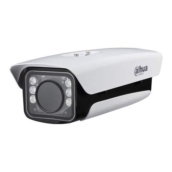
Product Overview Light-duty protective housing provides all-weather protection for cameras and lens, and ensures their normal work in severe environment such as high temperature, low temperature, rain and snow. Support to install cameras and lens of various sizes; boast a built-in adjustable camera fixing plate and relatively high protection level. - Page 7 Figure 1-2 (unit: mm) DH-PFH610N-IR/LED, DH-PFH610A-IR, DH-PFH610A and DH-PFH610A-H Figure 1-3 DH-PFH610N-W and DH-PFH610N-IR-W (unit: mm)
-
Page 8: Installation Guide Of Housing
Installation Guide of Housing Open and Lock the Housing Open or lock the housing with two M6 screws at the side and internal hexagonal wrench (5.0mm), as shown in Figure 2-1. Figure 2-1 Before closing the cover, please inspect whether waterproof ring of the shell is correctly installed in place, as shown in Figure 2-2. -
Page 9: Control And Wiring Instruction
Control and Wiring Instruction With LED/wiper module, there are 3 control modes as shown in Mode Applicable IPC Camera Type Wiring Instruction Remote 1 Camera with RS485 control Control LED and wiper status at WEB function. interface. Specific wiring of IPC is shown in Figure 2-3 Wiring Diagram of IPC Interface (Remote Mode 1). - Page 10 interface has “External Light Setting” and “Wiper Setting”. Choose corresponding control mode according to different camera types. “N/C”, “NO/C” and “OUT/G” interfaces of the camera have the same functions. Different types of devices display in a different way. Regarding a camera with RS485 control function, “PTZ Setting”...
- Page 11 Figure 2-4 Wiring Diagram of IPC Interface (Remote Mode 2)
- Page 12 Figure 2-5 Wiring Diagram of IPC Interface (Routine Mode)
- Page 13 Wiring Diagram of CVI Interface (Remote Mode 1) Figure 2-6...
- Page 14 Wiring Diagram of CVI Interface (Routine Mode) Figure 2-7 Position Interface Instruction AC24V Power input interface, to connect external power. Power output interface, consistent with external power supply, to supply power to the camera. In remote mode 1, this is LED and wiper control interface. 485 (A/B) In remote mode 2 and routine mode, it is ok if this interface is not connected.
-
Page 15: Install Camera
Install Camera Step 1 Take camera installation plate out of the housing. Step 2 Fix the camera onto camera installation plate. Step 3 Fix camera installation plate onto housing shell, as shown in Figure 2-8. During installation of camera lens, try to get close to inner surface of glass (1-3mm away from ... - Page 16 other two modes, dial switch can be turned to 1 or 2, so corresponding IR lamp can be turned off (at most 4 lamps can be turned off), in order to meet short-distance fill-in light requirement. Figure 2-9...
-
Page 17: Installation Guide Of Bracket
Installation Guide of Bracket Install General Bracket Protective housing can be installed with a bracket, which owns general threaded holes. Threaded holes (M6) of general bracket on protective housing are shown in Figure 3-1. Figure 3-1 Install Special Bracket Special bracket means integration of housing and bracket, and thus supports concealed wiring. Step 1 Wiring harness goes through the bracket, as shown in Figure 3-2. -
Page 18: Bracket Model
Figure 3-3 Figure 3-4 During wiring, it is suggested that wiring harness should divide into signal harness and power harness, go out of two holes respectively and connect waterproof joints. If all wires goes out of one hole and connect waterproof joint, it is suggested that the other hole should be covered with waterproof plug, in order to prevent water leakage. - Page 19 Hanging Mode Schematic Diagram Bracket Model Ceiling DH-PFB600W installation Wall installation DH-PFB604W Plane DH-PFA162 installation Cross-bar DH-PFA150+DH-PFA162 installation Vertical DH-PFB601W installation 1 Vertical DH-PFB601W+DH-PFA112 installation 2 (200mm) or DH-PFA113 (400mm) Table 3-1...
-
Page 20: Technical Specification
Technical Specification Product Model DH-PFH610N DH-PFH610A DH-PFH610N-H DH-PFH610A-H Product Size(L×W×H) 404mm×164mm×132mm Max. Size of Camera 255mm×90mm×70.5mm or 255mm×90mm×83mm (L×W×H) 215mm×90mm×83mm Φ60mm Φ60mm Window Area 100mm×80mm 100mm×80mm Weight 2.5kg 2.7kg Material AL + PC Protection Level IP67 Installation Indoor/outdoor Environment Working Temperature -30℃~+60℃... - Page 21 Control Range OFF: 20± 5℃ (Cooling) Infrared Distance 0m~100m 0m~100m White Light 0m~60m Distance Anti-corrosion Wiper Vandal Resistance ZHEJIANG DAHUA VISION TECHNOLOGY CO.,LTD. Address:No.1199, Bin'an Road, Binjiang District, Hangzhou, P.R. China Postcode: 310053 Tel: +86-571-87688883 Fax: +86-571-87688815 Email:overseas@dahuatech.com Website: www.dahuasecurity.com...
Need help?
Do you have a question about the PFH610V-IR and is the answer not in the manual?
Questions and answers