mectron compact piezo LED Installation Manual
Hide thumbs
Also See for compact piezo LED:
- Use and maintenance manual (52 pages) ,
- Manual (28 pages) ,
- Use and maintenance manual (29 pages)
Table of Contents
Advertisement
Quick Links
Advertisement
Table of Contents

Related Manuals for mectron compact piezo LED


Summary of Contents for mectron compact piezo LED
- Page 1 LED INSTALLATION MANUAL 0051 0051...
- Page 2 LeD...
- Page 3 Copyright © mectron S.p.a. 2022. all rights reserved. No part of this document can be reproduced in any form without the written consent of the copyright owner.
-
Page 4: Table Of Contents
LeD TABLE OF CONTENTS Introduction intended Use Description of the Device Disclaimer Safety precautions Symbols Identification Data 2.1 Device Identification Label 2.2 Handpiece Identification Data 2.3 Insert Tips Identification Data Delivery List of components Installation Safety precautions During installation mechanical installation electrical connections 4.3.1 alternate 24V power Supply 4.3.2... - Page 5 Casing to the Wireless RF Communications Device Troubleshooting 7.1 Diagnostic System 7.2 Troubleshooting Quick Guide 7.3 Customer Service - Returns and/or Repairs 7.3.1 Repairs 7.3.2 Returned Goods Warranty...
- Page 6 LeD PAGE INTENTIONALLY LEFT BLANK...
-
Page 7: Introduction
• contact piezosurgery inc. after Sales Service. NOTE: Identifies special information to clarify or emphasize important instructions. Intended Use the compact piezo LeD is an ultrasonic piezoelectric scaler intended for use, with the appropriate associated insert tips, in the following dental applications: • Scaling: procedures for removal of crown preparations, inlay/onlay of supra-gingival/sub-gingival and condensation, implants/restorations interdental calculus/plaque deposits;... -
Page 8: Description Of The Device
Description of the Device compact piezo LeD is a multifunctional settings. ultrasonic piezoelectric scaler. it has been the device has an automatic sync circuit designed in order to offer a product with... -
Page 9: Safety Precautions
Interference from other equipment. efficient. In case of operating abnormalities, an electrical scalpel or other electro-surgical Do Not perform the treatment. contact an units near the compact piezo LeD device may authorized piezosurgery inc. Service center if interfere with its correct operation. the abnormalities concern the device. WARNING: Contraindications. - Page 10 LeD if the layer of titanium nitride (golden WARNING: Infections control. surface), where present, is visibly worn, the to ensure maximum safety of the patient and insert tip must be replaced. the use of a worn the operator, before using all the reusable insert tip decreases its efficiency. parts and accessories, make sure you have...
-
Page 11: Symbols
iNtRoDUctioN Symbols Symbol Description Symbol Description Device compliant with Regulation (EU) memKo mark 2017/745. Notified UL-cSa compliance 0051 body: IMQ S.p.A. caUtioN, See consult instructions instructions for use. for use manufacturer Date of manufacture manufacturer, year of manufacture included Serial Number (YYYY= year) YYYY Lot Number product Number Single-Use expiring date... -
Page 12: Identification Data
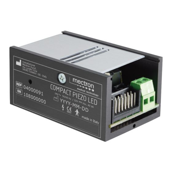
Mectron S.p.A. Via Loreto 15/a number. the iD label is located on the 16042 Carasco -GE- Italy COMPACT PIEZO LED side of the compact piezo LeD module. 50/60 Hz / 32V Min. 40 VA The complete technical specifications are 04000091 YYYY-MM-DD provided in... -
Page 13: Handpiece Identification Data
SLIM MANIPOLO ABLATORE 114000000 SLIM Data Matrix HIBC 128 03120238 Insert Tips Identification Data on each insert tip is laser-marked the name the insert tip itself (Reference 2), the mectRoN logo (Reference 3) and the lot number to which the insert tip belongs (Reference 4). -
Page 14: Delivery
DELIVERY List of Components Figure 1 a pagina 10. can be ordered separately (see table 4 a compact piezo LeD is supplied with the pagina 9). standard equipment (see table 2 a pagina NOTE: Both the items included in the 8), a set of variable accessories depending... - Page 15 03120142 SCALER HANDPIECE) Front cone for LED SCALER Front cone for LED handpiece 03020158 HaNDpiece Front cone for LED SCALER Front cone without light 03020171 HaNDpiece Front cone, light guide and Light guide kit 02900146 decorative ring for SLim scaler handpiece Table 4 – accessories available for separate order. b) produced by mectron.
- Page 16 Keep the packaging in case any items need to storage must be carried out with particular be sent to an authorised mectRoN Service care. centre and to store the appliance during long all the material sent by mectRoN was periods of non-use.
-
Page 17: Installation
INSTALLATION compact piezo LeD, in order to operate must standards: be connected to a dental unit. • ISO 7494 Dentistry – Stationary dental the dental unit mechanically houses the pilot units and dental patient chairs; module, supplies power to the module, and • ISO 60601-1 Medical electrical supplies water to cool the handpieces and equipment – Part 1: General... -
Page 18: Mechanical Installation
LeD CAUTION: in the case that the end WARNING: Risk of explosion. user, when operating in his or her own the device cannot operate in environments medical study or clinic, must subject the where there are saturated atmospheres of electro-medical equipment and systems to... -
Page 19: Electrical Connections
Electrical Connections compact piezo LeD allows various electrical For the electrical connections, the configurations to satisfy the characteristics of compact piezo LeD device is equipped with 2 the dental unit in which it is housed. connectors (see Figure 3 a pagina 13 the dental units to which the • M1 : connector with 2x8 contacts for the compact piezo LeD device can be connected module controls;... -
Page 20: Alternate 24V Power Supply
LeD M2 Connector Pin-Out M3 Connector Pin-Out Pin Signal Pin Signal Vout handpiece LeD a Neutral LeD K Table 6 – m2 connector pin-out. Table 7 – m3 connector pin-out. 4.3.1 Alternate 24V Power Supply To power the module at 24V~ 50/60 Hz Figure 3 a connect pins 13 and 14 (see pagina 13 and table 5 a pagina 13). -
Page 21: Power Regulation
4.3.3 Power Regulation the compact piezo LeD piezoelectric module different modes explained below, covering allows regulation of the handpiece power by the needs of most dental units available on means of the controls on the dental unit, in the market. -
Page 22: 0-5 V Power Regulation
12 and 10. 0-10V 1mA 10 kOhm 1/8W, 1% resistance 4.3.4 Solenoid Valve Control the compact piezo LeD provides an enabling in output for a solenoid valve Solenoid valve (optional) on the handpiece irrigation circuit. the 24V 2,5W output distributes 24V with maximum... -
Page 23: Enabling
iNStaLLatioN 4.3.5 Enabling These connections allow the activation of the operating cycle. For these connections too, there are different configurations to suit the different types of dental units. 4.3.5.1 Enabling of Pedal with Negative Signal the pedal must be connected to pins 10 and 7. Pedal 4.3.5.2 Enabling of Pedal with Positive Signal the pedal must be connected to pins 8 and 11. Pedal 4.3.6 Other Connections Pins 1 and 16 must always be connected to each other. -
Page 24: Connecting The Cord Of The Scaler Handpiece
LeD 4.3.7 Connecting the Cord of the Scaler Handpiece connect the piezoelectric pilot wires of the cord to the m2 terminal in accordance with the indicated polarity. Connect the LED wires (purple and grey of the handpiece cord) to connector m3 in accordance with the indicated polarity. CAUTION: Do not invert the position CAUTION: Do not wire the red and black... -
Page 25: Layout A
±10%) is provided by contact with the instrument tray and consent is provided by the pedal. The power is regulated by a 2.2KΩ linear potentiometer (see Figure 6 a pagina 19 Fuse holder, fuse, pedal and instrument tray not included in Pedal 2,2 KΩ linear the Mectron supply potentiometer Power supply Yellow 24 V ~ 50/60 Hz or Instrument tray Fuse 32 V Yellow... -
Page 26: Layout C
LeD 4.3.8.3 Layout C the power supply (32 V ±10%) is provided by contact with the instrument tray and positive consent is provided by the pedal. The power is regulated by a 2.2KΩ linear potentiometer (see Figure 7 a pagina 20 ). This type of connection allows very rapid ON/OFF cycles and does not occupy the external power circuit with high loads. 2.2 KΩ linear Pedal Instrument tray Fuse potentiometer Positive Power supply Yellow T 2 A 32 V Yellow... -
Page 27: Layout E
The power supply (24 V~ 50/60 Hz ±10% or 32 V ±10%) and consent are provided by the pedal. The power is regulated by a 4.7KΩ linear potentiometer (see Figure 9 a pagina 21 Fuse holder, fuse and pedal are not included in the Mectron supply 4,7 KΩ linear potentiometer Power supply Yellow 24 V ~ 50/60 Hz or Pedal... -
Page 28: Layout G
LeD 4.3.8.7 Layout G The power supply (24 V~ 50/60 Hz ±10% or 32 V ±10%) and consent are provided by the pedal. the power is regulated by a variable voltage between 0 and 5 V (see Figure 11 a pagina 22). Fuse holder, fuse and pedal... -
Page 29: Water Connection
Water Connection the compact piezo LeD requires a water and solenoid valve, be fitted with supply line to cool the handpiece and inserts a valve dedicated to supplying the during the operating cycle. compact piezo LeD handpiece and able the device is sold with a connecting cable... -
Page 30: Methods And Precautions For Disposal
LeD METHODS AND PRECAUTIONS FOR DISPOSAL WARNING: Hospital waste. treat the compact piezo LeD must be disposed of and following objects as hospital waste: treated as waste subject to separate collection. Failure to comply with the previous points can • inserts, when worn or broken; result in a penalty pursuant to the directive •... - Page 31 tecHNicaL Data Solenoid valve control output 24V , 2.5W adjustable depending on the type of Water supply installation. Working pressure from 1 to 6 bar. adjustable accordance with indications provided by the manufacturer Handpiece LED system of the dental unit. White LeD light power risk free according to standard IEC/EN 62471. missing handpiece; Breaking wire cord; Protections of the APC Circuit insert not correctly tightened or broken;...
-
Page 32: Guidance And Manufacturer's Declaration - Electromagnetic Emissions
LeD device may interfere with its correct operation. 6.1.1 Guidance and Manufacturer’s Declaration - Electromagnetic Emissions compact piezo LED is intended for use in the electromagnetic environment specified below. The customer or user of compact piezo LeD should ensure that it is used in such an environment. Emissions Test Compliance Electromagnetic environment – Guidance compact piezo LeD only uses RF energy for internal function. Therefore, its FR emissions... -
Page 33: Accessible Parts Of The Casing
Data 6.1.2 Accessible Parts of the Casing compact piezo LED is designed to operate in the electromagnetic environment specified below. the customer or user of compact piezo LeD should always make sure that it is used only in such an environment. Basic EMC Electromagnetic Phenomenon standard or test Immunity test levels environment - Guidance method The floor must be made of wood, concrete or ceramic electrostatic ±8 kV on contact tiles. If the floor is covered... -
Page 34: Guidance And Manufacturer's Declaration - Electromagnetic Immunity
LeD 6.1.3 Guidance and Manufacturer’s Declaration - Electromagnetic Immunity 6.1.3.1 A.C. Input Power Connection compact piezo LED is designed to operate in the electromagnetic environment specified below. the customer or user of compact piezo LeD should always make sure that it is used only in such an environment. Basic EMC Electromagnetic Phenomenon standard or test Immunity test levels... - Page 35 ME EQUIPMENT and ME SYSTEMS that does not have voltage within the compact piezo LeD RateD voltage a surge protection device in the primary power circuit range. if the compact piezo LeD is tested at one may be tested only at ± 2 kV line(s) to earth and ± 1 power input voltage, it is not necessary to re-test at kV line(s) to line(s).
-
Page 36: Points Of Contact With The Patient
LeD 6.1.3.2 Points of Contact with the Patient compact piezo LED is designed to operate in the electromagnetic environment specified below. the customer or user of compact piezo LeD should always make sure that it is used only in such environment. Basic EMC Electromagnetic Phenomenon standard or test Immunity test levels environment - Guidance method The floor must be made of wood, concrete or ceramic electrostatic ±8 kV on contact tiles. If the floor is covered... -
Page 37: Parts Accessible To The Input / Output Signals
Data 6.1.3.3 Parts Accessible to the Input / Output Signals compact piezo LED is designed to operate in the electromagnetic environment specified below. the customer or user of compact piezo LeD should always make sure that it is used only in such an environment. Basic EMC Electromagnetic Phenomenon standard or test Immunity test levels environment - Guidance method The floor must be made of wood, concrete or ceramic electrostatic ±8 kV on contact tiles. If the floor is covered... - Page 38 Specifications of the Tests for the Immunity of the Accessible Parts of the Casing to the Wireless RF Communications Device compact piezo LeD is designed to operate in an electromagnetic environment in which radiated RF disturbances are under control. The customer or the user of compact piezo LED can help...
- Page 39 30 cm ( 12 is permitted by IEC 61000-4-3. inches) to any part of the compact piezo LED device, including cables specified by the manufacturer. otherwise, degradation of the performance of this equipment could result. TROUBLESHOOTING Diagnostic System compact piezo LeD is equipped with a on the control module via a red/green LED diagnostic circuit that allows detecting light.
- Page 40 LeD Device Powered With Pedal Activation Description • tuning scan failed protection activated: • insert tip not present or not properly tightened on the handpiece; Red LED flashing • the insert tip is worn, broken or deformed; • Handpiece/cord contacts wet. Troubleshooting Quick Guide Problem Possible Cause Solution Handpiece not connected to connect the handpiece to the cord.
- Page 41 Service center Unscrew and correctly screw the insert tip back by using the insert tip is not correctly the mectron torque wrench chapter 4.4 on page tightened on the handpiece (see poor performance of the Use and...
- Page 42 LeD Customer Service - Returns and/or Repairs if you need technical assistance regarding the please provide the following information: use, or you encounter a problem that requires • Data of the owner with telephone servicing or repair, contact PIEZOSURGERY number; Inc. Customer Service at (1.888.87-PIEZO). • product name;...
- Page 43 WARRANTY WARRANTY non-approved usage authorized. compact piezo LeD will void the warranty. Contact PIEZOSURGERY inc. customer Service ® Any usage of non-PIEZOSURGERY parts, at 1.888.87-PIEZO for return authorization. ® tips, components or procedures will void the this warranty is valid only if the product is warranty.
- Page 44 Distributed in U.S. by: Manufacturer: mectron S.p.a. Via Loreto 15/A 850 michigan avenue columbus, ohio 43215 16042 Carasco (Ge) Italy Phone 614.459.4922 Tel. +39 0185 35361 Fax 614.459.4981 Fax +39 0185 351374 www.piezosurgery.us www.mectron.com e-mail: info@piezosurgery.us e-mail: mectron@mectron.com Reseller...
Need help?
Do you have a question about the compact piezo LED and is the answer not in the manual?
Questions and answers