Advertisement
Quick Links
Advertisement

Related Manuals for PG BISON BLUM FLATPAX 367779


Summary of Contents for PG BISON BLUM FLATPAX 367779
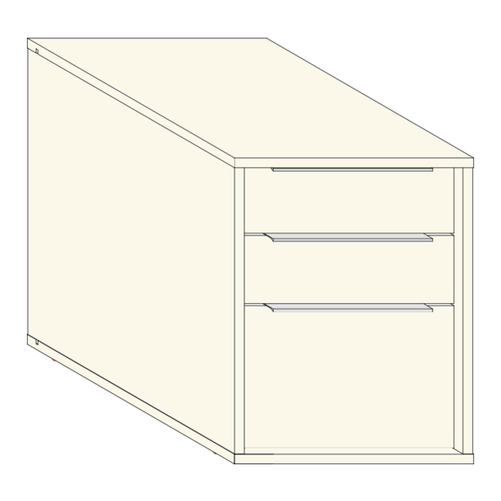
- Page 1 BLUM FLATPAX OFFICE FURNITURE RANGE ASSEMBLY GUIDE 3 - DRAW PEDESTAL TOTAL NUMBER OF PANELS: 23...
-
Page 2: Tools Required
HARDWARE PRODUCT IMAGE Dufix Minifix Wooden Dowel Screw 3.5 x 16mm Tandem Single Extension Runners 270mm 3 pairs Left & Right 3 pairs Locking Devices Left & Right Screw 4 x 30mm Front Adjusters Dome Screws Handle J9913 260mm Glides TOOLS REQUIRED Screw Driver Rubber Mallet... - Page 3 CARCASS ASSEMBLY D - Top C - Floor Bottom E - Back A - Visible Side Left B - Visible Side Right NUMBER OF PANELS: 5...
-
Page 4: General Instructions
GENERAL INSTRUCTIONS 1. Confirm that all panels (5) are in the package before assembling. 2. Check the white sticker on each panel for the labelling (A - E). 3. Ensure that the panels are laid on a non-abrasive surface when assembling. - Page 5 STEP 1 50 mm 50 mm 10 mm 10 mm 10 mm 10 mm 50 mm 50 mm Using a rubber mallet, knock in the Plastic Glides in the shown positions on panel C. Refer to the indicated dimensions for positioning. Note that the glides go on the face without holes. STEP 2 With panel C sitting on the glides, connect panels A &...
- Page 6 STEP 3 Slide panel E through the grooves on panels A and B and into the groove on panel C. STEP 4 Det. 9 Connect panel D to panels A & B as shown. Note that the groove on panel D goes into the revealed edge on panel E (See Det.
- Page 7 STEP 5 First, use these screws to align the runner holes with the predrilled pilot holes. Then, reinforce the runners by adding screws in the shown Left Runner positions. Det. 10 Screw in the Left Tandem Runner in the shown positions on panel A. See Det. 10. STEP 6 First, use these screws to align the runner...
- Page 8 DRAWER BOX ASSEMBLY 1 T - Drawer Box Bottom R - Drawer Box Back P - Left Box Side Q - Right Box Side) S - Drawer Box Sub Front TOTAL NUMBER OF PANELS: 5 GENERAL INSTRUCTIONS 1. Confirm that all panels (5) are in the package before assembling. 2.
- Page 9 STEP 1 Connect panel R to panel Q as shown. Refer to the holes and/or grooves on the diagram to determine the panel orientation. STEP 2 Connect panel P to panel R as shown. Refer to the holes and/or grooves on the diagram to determine the panel orientation.
- Page 10 STEP 3 Connect panels P & Q to panel S as shown. Refer to the holes and/or grooves on the diagram to determine the panel orientation. STEP 4 Slide 3mm panel T through the grooves on panels Q & P and into the groove on panel S as shown. Refer to the holes and/or grooves on the diagram to determine the panel orientation.
- Page 11 STEP 5 Screw 3.5 x 16mm Secure the 3mm panel T onto panel R using Screw 3.5 x 16mm. Refer to the holes and/or grooves on the diagram to determine the panel orientation. STEP 6 Screw 3.5 x 16mm Locking Device Left &...
- Page 12 STEP 7 Front Adjustment Bracket Using a rubber mallet, gently knock in the Front Adjustment Brackets into panels W in the shown positions. Confirm that they go all the way in such that no part appears above the surface of the panel.
- Page 13 STEP 9 Screw 3.5 x 16mm Using Screw 3.5 x 16mm, screw in the handles onto panel W in the shown position. Confirm that the holes on the handles align with the pilot holes on panel W . STEP 10 Insert the Drawer Box as shown.
- Page 14 STEP 11 2.5 mm 2.5 mm Det. 6 Fig. 1 Screw 4.0 x 30mm Adjust panels W to achieve the clearance shown in Det.6. This is done by knocking the drawer face (Panels W) in the desired direction until the clearances in Det.6 are attained. When done, reinforce the panel S - panel W connection by adding Screws 4.0 x 30mm in the remaining holes on panel S.
- Page 15 DRAWER BOX ASSEMBLY 2 DP - Drawer Box Bottom (2) DB - Drawer Box Back (2) DL - Left Box Side (2) DR - Right Box Side (2) DF - Drawer Box Sub Front (2) NUMBER OF PANELS: 10 GENERAL INSTRUCTIONS 1.
- Page 16 STEP 1 Connect panel DB to panel DL as shown. Refer to the holes and/or grooves on the diagram to determine the panel orientation. STEP 2 Connect panel DR to panel DB as shown. Refer to the holes and/or grooves on the diagram to determine the panel orientation.
- Page 17 STEP 3 Connect panels DL & DR to panel DF as shown. Refer to the holes and/or grooves on the diagram to determine the panel orientation. STEP 4 Slide 3mm panel DP through the grooves on panels DL & DR and into the groove on panel DF as shown.
- Page 18 STEP 5 Screw 3.5 x 16mm Secure the 3mm panel DP onto panel DB using Screw 3.5 x 16mm. Refer to the holes and/or grooves on the diagram to determine the panel orientation. STEP 6 Screw 3.5 x 16mm Locking Device Left &...
- Page 19 STEP 7 Front Adjustment Bracket Using a rubber mallet, gently knock in the Front Adjustment Brackets into panels U & V in the shown positions. Confirm that they go all the way in, such that no part appears above the surface of the panel.
- Page 20 STEP 9 Screw 3.5 x 16mm Using Screw 3.5 x 16mm, screw in the handles onto panels U & V in the shown position. Confirm that the holes on the handles align with the pilot holes on panels U & V . STEP 10 Insert the Drawer Boxes as shown.
- Page 21 STEP 11 4 mm Det. 6 Fig. 1 Screw 4.0 x 30mm Adjust panels U & V to achieve the clearance shown in Det.6. This is done by knocking the drawer faces (Panels U & V) in the desired direction until the clearances in Det.6 are attained. When done, reinforce the panel DF - panel U &...
Need help?
Do you have a question about the BLUM FLATPAX 367779 and is the answer not in the manual?
Questions and answers