
Related Manuals for Golander pump BT100F


Summary of Contents for Golander pump BT100F
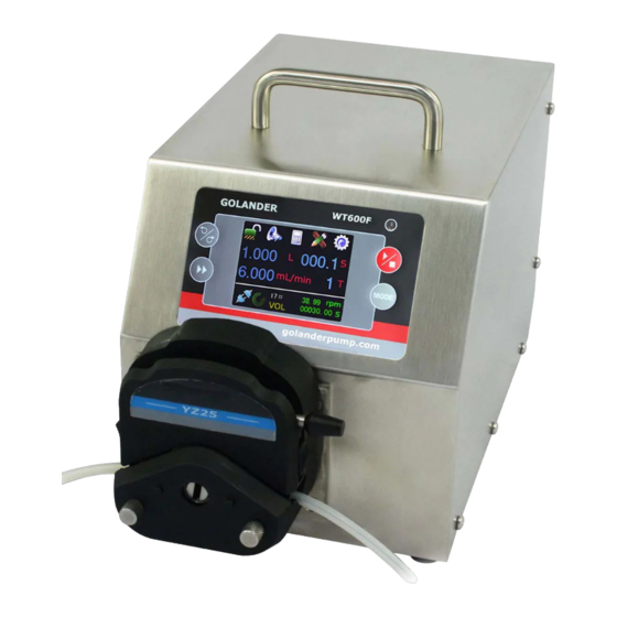
- Page 1 GOLANDER BT100F/300F/600F Intelligent Dispensing Peristaltic Pump Operating Manual...
-
Page 2: Table Of Contents
Contents Safety Precautions .................. 1 1 Description ................... 6 2 Functions and Features ................ 6 3 Components and Connectors ............... 8 4 Display Panel and Operating Keypad........... 9 4.1 Keypad ..................9 4.2 LCD Touch Screen Display ............10 4.3 Status bar ................. 10 5 Operation zone ................... -
Page 3: Safety Precautions
BT100F/BT300F/BT600F Peristaltic Pump Safety Precautions Danger Use the correct voltage indicated on the rating plate label of the pump • to avoid any damage. Do not make any unauthorized dismantling, changes or modifications • to the pump which could result in malfunctions or even potential accidents. - Page 4 BT100F/BT300F/BT600F Peristaltic Pump (DE) SICHERHEITSHINWEISE Gefahr Verwenden Sie die richtige Spannung, die auf dem Typenschild der Pumpe • angegeben ist, um Schäden zu vermeiden. Nehmen keine unbefugten Demontagen, Änderungen oder • Modifikationen an der Pumpe vor, die zu Fehlfunktionen oder sogar zu Unfällen führen könnten.
- Page 5 BT100F/BT300F/BT600F Peristaltic Pump (FR) CONSIGNES DE SÉCURITÉ Danger • Utilisez la tension correcte indiquée sur la plaque signalétique de la pompe afin d'éviter tout dommage. Ne procédez pas à des démontages, changements ou modifications non • autorisés de la pompe qui pourraient entraîner des dysfonctionnements, voire des accidents.
- Page 6 BT100F/BT300F/BT600F Peristaltic Pump (ES) INSTRUCCIONES DE SEGURIDAD Peligro Utilice la tensión correcta indicada en la placa de características de la bomba • para evitar daños. No realice ningún desmontaje, cambio o modificación no autorizada en la • bomba que pueda provocar un mal funcionamiento o incluso accidentes.
- Page 7 BT100F/BT300F/BT600F Peristaltic Pump (IT) ISTRUZIONI DI SICUREZZA Pericolo Usare la tensione corretta indicata sull'etichetta della targhetta della pompa • per evitare qualsiasi danno. Non eseguire smontaggi, cambiamenti o modifiche non autorizzati alla • pompa che potrebbero causare malfunzionamenti o addirittura potenziali incidenti.
-
Page 8: Description
BT100F/BT300F/BT600F Peristaltic Pump 1 Description BT-F series of intelligent dispensing peristaltic pumps are designed for precise metering and quantitative dispensing of liquids and to realize high-precision flow transmission. The latest version of this series adopted a larger true color LCD touch screen to improve the ease of use and to allow a more comprehensive information display. - Page 9 BT100F/BT300F/BT600F Peristaltic Pump Flow display and calibration. • Three dispense modes: Time Dispense Mode, Volume Dispense • Mode, Loop Dispense Mode. Store 5 groups of working parameters for 4 work modes (flow • mode and three dispense modes) Store 30 groups of working parameters for loop dispense mode •...
-
Page 10: Components And Connectors
BT100F/BT300F/BT600F Peristaltic Pump 3 Components and Connectors Handle Driver Color LCD Touch Screen Coupler Pump Head Mounting Bracket RS232 DB15 External Control Interface Power Switch Fuse Power Connector Cooling Fan Figure 1. Components and Connectors... -
Page 11: Display Panel And Operating Keypad
BT100F/BT300F/BT600F Peristaltic Pump 4 Display Panel and Operating Keypad LCD DISPLAY BT600F DIRECTION START/STOP PRIME MODE MODE Figure 2. Display Panel 4.1 Keypad START/STOP key. Press to start or stop the pump. DIRECTION Key. Press to change the drive's rotating direction, clockwise or counterclockwise. -
Page 12: Lcd Touch Screen Display
BT100F/BT300F/BT600F Peristaltic Pump 4.2 LCD Touch Screen Display 34℃ 12:35:46 Status bar Flow Delayed Start 9.000 mL/min 00:00:00 Operation display Delayed Stop 150.0 00:00:00 Speed Navigation FLOW button Figure 3. Main screen 4.3 Status bar A. Tone. 34℃ 12:35:46 34℃... - Page 13 BT100F/BT300F/BT600F Peristaltic Pump 34℃ 12:35:46 34℃ 12:35:46 Flow Flow Delayed Start Delayed Start 9.000 9.000 00:00:00 00:00:00 uL/min uL/min Delayed Stop Delayed Stop 150.0 00:00:00 150.0 00:00:00 Speed Speed FLOW FLOW Keypad unlocked Keypad locked Figure 5 Keypad Lock C. Control Modes.
- Page 14 BT100F/BT300F/BT600F Peristaltic Pump Current Control Mode: An external 4-20mA analog current signal controls the flow rate. An external logic level signal controls the start/stop. The keypad is disabled. 34℃ 12:35:46 Flow 4mA Speed 9.000 uL/min 20mA Speed 600.0 150.0 Speed...
- Page 15 BT100F/BT300F/BT600F Peristaltic Pump 12:35:46 34℃ Flow 0V Speed 9.000 uL/min 10V Speed 150.0 600.0 Speed FLOW Figure 10 0-10V Voltage Control Mode D. Communication State. 12:35:46 34℃ 12:35:46 34℃ Flow Flow Delayed Start Delayed Start 9.000 9.000 00:00:00 00:00:00 uL/min...
-
Page 16: Operation Zone
BT100F/BT300F/BT600F Peristaltic Pump below for clockwise rotation. 34℃ 12:35:46 34℃ 12:35:46 Head: YZ15 Flow Delayed Start Tube: 流量 Flow 9.000 00:00:00 uL/min 9.000 Speed: 150.0 rpm 毫升/分 Elapsed: 0.000 uL Delayed Stop ul/min 00:00:00 Total: 13.980 mL 00:00:00 150.0 Speed 转/分... -
Page 17: Navigation Buttons
BT100F/BT300F/BT600F Peristaltic Pump Flow unit Setting uL/min mL/min L/min Figure 15 Choose Flow Rate Unit 6 Navigation Buttons Mode Settings - Set specifics for different operating modes, including tone on/off and lock on/off. Mode Settings Mode Settings Dispense Control Mode Internal Ctrl NO.1... - Page 18 BT100F/BT300F/BT600F Peristaltic Pump Preview mode - View running status and parameter changes. The current running parameters display on the left side of the interface, while the running status is shown on the right side. 34℃ 12:35:46 Head: YZ15 Tube: 流量...
- Page 19 BT100F/BT300F/BT600F Peristaltic Pump Counter clockwise operation Clockwise operation Flow Flow Flow Flow 9.000 9.000 9.000 9.000 mL/min mL/min mL/min mL/min Figure 20 Direction Indication In the dispense mode, red in the center means stop, green means in operation, and yellow means pause.
- Page 20 BT100F/BT300F/BT600F Peristaltic Pump Note: If an accurate display of the flow rate is required, a flow rate calibration must be carried out. System Menu - When the pump is not running, press the icon to enter the System Menu. Setup...
- Page 21 BT100F/BT300F/BT600F Peristaltic Pump Pump Head YZ15 YT15 WMD15 Suitable for wall thickness 1.6mm YZ25 tubing. Figure 25 Pump Head Selection • Tube Settings : Choose the appropriate tubing size for the selected pump head. Swipe up and down to view the menu, as shown in Figure 26.
- Page 22 BT100F/BT300F/BT600F Peristaltic Pump Anti-Drip Figure 27 Anti-drip Settings • Anti-speed : Set the reverse speed as needed. Anti-Speed Min: 100 Max: 600 Figure 28 Anti-Speed Setting • Communication settings - Sets the parameters of RS485 communication, as shown in Figure 29.
- Page 23 BT100F/BT300F/BT600F Peristaltic Pump and down to view the menu. General Settings General Settings External Direction Irda Pulse signal External Direction Deceleration Time Pulse signal 0.5S Deceleration Time Pulse Control 0.5S Falling edge Pulse Control Level Control Falling edge Low level Figure 30 General Settings (Advanced) •...
- Page 24 BT100F/BT300F/BT600F Peristaltic Pump Level Control Low Level High level Figure 32 Level Signal Calibrate wizard - In order to improve the flow accuracy of liquid delivery, it is necessary to calibrate the flow rate. According to the wizard prompts, measure the delivered liquid using a balance or a measuring cylinder to make the display value correspond to the actual flow accurately.
- Page 25 BT100F/BT300F/BT600F Peristaltic Pump Date Settings December 2017 Mo Tu We Th Fr Sa Su 15 16 17 22 23 24 29 30 31 Figure 34 Date Setting • Time : Set Hour, Minute and Seconds by using the UP and DOWN buttons.
- Page 26 BT100F/BT300F/BT600F Peristaltic Pump pressing and holding the direction key and mode key MODE when powering up the pump. Release the keys after a beep. Factory Reset Warning! The system will be restored to factory default settings. Cancel Figure 37 Factory Reset •...
-
Page 27: External Control Interface
BT100F/BT300F/BT600F Peristaltic Pump Password Password Figure 40 Password Setting Return- Return to the main screen. 7 External Control Interface DB15 Mark Note ADC_W Positive of external analog input Communication interface, B pole of RS485 Communication interface, A pole of RS485... -
Page 28: Operation Instructions
BT100F/BT300F/BT600F Peristaltic Pump No. DB9 Mark Note Receiving data Send data Signal ground line Table 2 RS232 definition 8 Operation Instructions 8.1 Before Operation 1) Please check the packing slip to ensure all parts are included and intact in the package. If there is a problem, please contact the manufacturer or distributor. -
Page 29: First Run Wizard
BT100F/BT300F/BT600F Peristaltic Pump 8.3 First Run Wizard Flow Rate Calibration Calibrate the flow rate by measuring the transferred liquid using a balance or a measuring cylinder, when • First time using the pump • The pump head is changed • Tubing is installed or replaced •... - Page 30 BT100F/BT300F/BT600F Peristaltic Pump Note : The fluid volume should not be less than the suggested value. 6) The test window is shown below. Calibrate Press START/STOP key to test, then input the data. Test1: 0.000 Test2: 0.000 Test3: 0.000 Figure 42 Calibration Pressing the Start/Stop key, the pump will start to transfer fluid.
-
Page 31: Working Mode
BT100F/BT300F/BT600F Peristaltic Pump • The tubing size setting • The liquid viscosity. When it is too high, the flow rate may not be linear to the speed. • If dual pump heads are used for one channel If there are no problems, press the to save the new value. - Page 32 BT100F/BT300F/BT600F Peristaltic Pump Working Mode Flow TimeDisp VolDisp LoopDisp Figure 45 Working Mode Flow Mode • The pump will run according to the set flow rate and record the cumulative fluid volume. In the main screen, the flow and flow unit can be set and the flow rate can be changed.
- Page 33 BT100F/BT300F/BT600F Peristaltic Pump Delayed Start Delayed Stop Hour Hour Minute Minute Second Second Cancel Cancel Figure 47 Delay Time Settings After setting the time, press the START/STOP key to start the delay process. An alarm icon will appear in the status bar, as shown below.
- Page 34 BT100F/BT300F/BT600F Peristaltic Pump The main interface parameters can be set as follows: A - Dispense volume for each dose, µL, mL or L. B - Dispense flow rate, µL/min or mL/min. C – Pause time. The time between doses. D - Dispense cycles. When the dispense cycle is set to zero, the pump will keep running until the START/STOP key is pressed.
- Page 35 BT100F/BT300F/BT600F Peristaltic Pump 34℃ 12:35:46 34℃ 12:35:46 Flow Head: YZ15 Tube: 1.00 60.00 1.000 Speed: 150.0 rpm uL/min Elapsed: 0.000 uL 00:00:00 Total: 13.980 mL Pause Cycle 转/分 Flow: 60.00 ul/min Time Disp 01 Time Disp 01 Figure 50 Time Dispense Mode A - Dispense duration for each dose B - Dispense flow rate, mL/min or L/min.
-
Page 36: External Control Mode
BT100F/BT300F/BT600F Peristaltic Pump By setting the operating steps and the number of cycles for each step, the pump automatically completes dispensing following the steps. Thirty steps are available with volume, flow rate, and pause time setting for each step. Setting can be saved under rogram. - Page 37 BT100F/BT300F/BT600F Peristaltic Pump CW_W ADC_ AGND RS_W VCC_W 0-5V/0-10V /4-20mA 5V/12V/24V DC Figure 52 DB15 Wiring with an External DC Power Source CW_W ADC_W AGND RS_W 0-5V/0-10V /4-20mA Figure 53 DB15 Wiring with the Internal 12V DC Power Source 2) Turn the power on. The pump will display the main screen.
-
Page 38: Communication Mode
BT100F/BT300F/BT600F Peristaltic Pump 34℃ 12:35:46 34℃ 12:35:46 Flow Flow 4mA Speed 0V Speed 9.000 9.000 uL/min uL/min 20mA Speed 5V Speed 150.0 600.0 600.0 150.0 Speed Speed FLOW FLOW Current Control Mode Voltage Control Mode Figure 54 Analog Control Interface... - Page 39 BT100F/BT300F/BT600F Peristaltic Pump VCC_W 12V DC Figure 55 Control Start/Stop with an External 12V Power Source Figure 56 Control Start/Stop with the Internal 12V Power Source 2) Turn the power on. The pump will display the main screen. 34℃ 12:35:46...
-
Page 40: Footswitch
BT100F/BT300F/BT600F Peristaltic Pump 4) The peristaltic pump communicates via RS485, with a default setting of 9600 communication rate, 8 data bits, an even parity check and a stop bit of 1. The parameters can be modified in the common parameters of the communication settings, as shown in... - Page 41 BT100F/BT300F/BT600F Peristaltic Pump RS_W VCC_W 12V DC Figure 59 Footswitch Control Start/Stop with external 12V Power Source RS_W Figure 60 Footswitch Control Start/Stop with the internal 12V Power Source If the pump is set to Volume, Time or loop Dispense Mode in the Internal Control Mode, the pump will start to dispense when the switch RS_W is closed and then opened.
-
Page 42: Maintenance
BT100F/BT300F/BT600F Peristaltic Pump 34℃ 12:35:46 Flow Delayed Start 9.000 uL/min 00:00:00 Delayed Stop 150.0 00:00:00 Speed FLOW Figure 61 Footswitch Control 9 Maintenance 9.1 Warranty The product comes with one-year labor and parts warranty. The limited warranty does not cover any damage that is caused by improper usage and handling. - Page 43 BT100F/BT300F/BT600F Peristaltic Pump 2. Check the wire connection between the motor and the driver board. 3. Check the wire connection between the driver and the main board. 4. Check the power voltage for the pump. Hardware Motor is 1. Check the wire connection between trembling the motor and the driver board.
-
Page 44: Dimensions
BT100F/BT300F/BT600F Peristaltic Pump 3. Check whether on the bus there are two pumps using the same address If a problem cannot be solved, please contact the manufacturer or distributor. This product is not medically approved. When used as a component in a medical device, the medical device itself requires medical certification. -
Page 45: Specifications
Relative humidity <80% IP grade IP31 Display TFT Touch Screen LCD, 65536 Colors Dimensions (LxWxH) 269X160X183mm Weight 5.5Kg BT100F Suitable Pump Heads and Tubing, Flow Parameters Flow rate per No. of Pump head Tubing size (mm) channel Channels (mL/min) DG6-1 (6rollers) Wall:0.8~1, ID:≤2.4... - Page 46 BT100F/BT300F/BT600F Peristaltic Pump 13# 14# 16# 19# 25# YZ15 0.0006~420 YZ25 15# 24# 0.16~420 13# 14# 16# 19# 25# YT15 0.006~570 17# 18# YT25 15# 24# 35# 36# 0.17~720 BT300F Suitable Pump Heads and Tubing, Flow Parameters Pump No. of...
- Page 48 Golander LLC Golander GmbH 4405 International Blvd Dechant-Heimbach-Str. 29 Ste B117, Norcross, GA 30093 53177 Bonn Germany Tel: +1 678-587-8806 Tel: +49 228 50446952 info@golanderpump.com info@golander.de www.golanderpump.com www.golander.de...
Need help?
Do you have a question about the BT100F and is the answer not in the manual?
Questions and answers