Table of Contents
Advertisement
Advertisement
Table of Contents

Related Manuals for SAMES KREMLIN Xcite


Summary of Contents for SAMES KREMLIN Xcite
- Page 1 ® ® Xcite + & Xcite + Light guns Instruction manual DRT582221110 B - 2023/01...
- Page 2 DRT582221110 B - 2023/01 No part of this document may be communicated or reproduced in any form, nor may its contents be used or communicated, without the express written permission of Sames. The descriptions and characteristics contained in this document are subject to change without notice. ©...
- Page 3 DRT582221110 B - 2023/01 Services Certification and referencing Sames is certified as a training centre by the DIRRECTE of the Auvergne Rhône Alpes region under the number 84 38 06768 38. Throughout the year, our company provides training courses that enable you to acquire the know-how required for the implementation and maintenance of your equipment in order to guarantee its long-term performance.
- Page 4 DRT582221110 B - 2023/01 Member of Exel group...
-
Page 5: Table Of Contents
Xcite®+ & Xcite®+ Light guns 1. Health and safety instructions - - - - - - - - - - - - - - - - - - - - - - - - - - - - - - - - - - - - 7 1.1. - Page 6 6.4.15. Procedure H1: Disassembly of the fitting (16) (for Xcite®+ Light guns) ..45 6.4.16. Procedure H2: Reassembly of the fitting (16) (for Xcite®+ Light guns) ..45 7.
-
Page 7: Health And Safety Instructions
DRT582221110 B - 2023/01 1. Health and safety instructions 1.1. Configuration of the certified equipment This manual defines the configuration of the certified equipment. 1.2. Marking 1.2.1. Description of the ATEX equipment Each device is marked with the name of the manufacturer, the device reference and important informations for the use of the device: air pressure, electrical power. - Page 8 DRT582221110 B - 2023/01 Description Sigle Sames Manufacturer’s brand Product name ® Xcite ® Xcite + Light CE: European conformity II 2 G : Use in explosive area II: Group II 2: Category 2 Surface equipment intended for use in environment...
- Page 9 DRT582221110 B - 2023/01 Each appliance is fitted with a nameplate bearing the name of the manufacturer, the appliance reference number, important information for the use of the appliance (pressure, power,...) and sometimes the pictogram shown opposite. The equipment is designed and manufactured with high quality materials and components that can be recycled and reused.
-
Page 10: Standards And Guidelines Applied
DRT582221110 B - 2023/01 1.2.2. Standards and guidelines applied The standards applied are as follows: • EN ISO 80079-36 Juin 2016 / EN ISO 80079-36 June 2016: Non-electrical equipment for use in potentially explosive atmospheres - Methodology and requirements - Explosive atmospheres - Part 36: non electrical equipment for use in potentially explosive atmospheres - Methodology and requirements. -
Page 11: Meaning Of The Pictograms
DRT582221110 B - 2023/01 1.3. Meaning of the pictograms Danger: Danger: Danger: Danger: Danger: Electricity Automatic start Hot parts or Risk of explosion General surfaces Danger: Danger: Danger: Danger: Danger: High pressure Pinching and/or Atex Zone Flammability hazard Corrosive products crushing Danger: Danger:... -
Page 12: Precautions For Use
DRT582221110 B - 2023/01 1.4. Precautions for use 1.4.1. General The equipment at your disposal is for professional use only. It must be used only for the purpose for which it was intended or designed. Read all operating instructions and labels carefully before operating the equipment. Personnel using this equipment must have been trained in its use. -
Page 13: Fire, Explosion, Static Electricity Hazards
DRT582221110 B - 2023/01 1.4.4. Fire, explosion, static electricity hazards Incorrect earthing, insufficient ventilation, flames or sparks can cause an explosion or fire which can lead to serious injury. To avoid these risks, especially when using the pumps, it is imperative to: •... -
Page 14: Hoses
DRT582221110 B - 2023/01 1.4.6. Hoses Recommendations for hoses: • Keep hoses away from traffic areas, moving parts and hot areas. • Never subject the product hoses to temperatures above 60°C / 140°F or below 0°C / 32°F. • Do not use the hoses to pull or move the equipments. •... -
Page 15: Warnings
DRT582221110 B - 2023/01 1.5. Warnings It is imperative that anyone with a pacemaker not use the equipment or enter the projection area. Indeed, high voltage can cause the pacemaker to malfunction. This equipment may be dangerous if not used, disassembled and reassembled in accordance with the rules specified in this manual and any applicable European Standard or national safety regulations. -
Page 16: Installation Rules
DRT582221110 B - 2023/01 1.5.1. Installation rules Environment Environmental risks must be controlled in the following manner: •Have a qualified electrician check for ground continuity. If ground continuity is not assured, check the terminal, wire and grounding point. Never operate the equipment without resolving this problem. •Using a conductive air hose (minimum internal Ø... -
Page 17: Important Recommendations
DRT582221110 B - 2023/01 1.6. Important recommendations 1.6.1. Non-intended use or foreseeable misuse Any use other than the use described in the paragraph, ’Intended use’ and in this operating manual, and any use that extends beyond the specified intended use, shall apply as non-intended use. The manufacturer shall not be liable damage resulting from non-intended use. -
Page 18: Recommendation Materials
DRT582221110 B - 2023/01 1.6.5. Recommendation materials • Our equipment must not be modified or used for purposes not intended. Any modification of the equipment made by the user and not authorized by Sames will result in loss of certification. •... -
Page 19: Warranty
DRT582221110 B - 2023/01 1.7. Warranty Sames grants a contractual warranty for a period of twelve (12) months from the date of availability to the customer provided that the conditions of use indicated in this technical manual are complied with. In order to be implemented, the warranty claim must define precisely, in writing the malfunction in question, must be accompanied by the defective material and/or component and must include the conditions under which the customer acquired the material from Sames. -
Page 20: Description
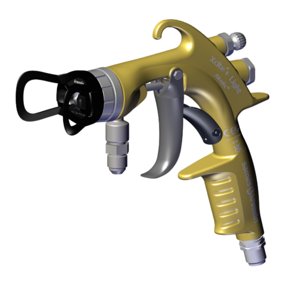
B - 2023/01 2. Description 2.1. General ® ® ® Xcite + and Xcite + Light guns have an Airmix finish: • High transfer rate: up 86%, • Designed to access hard-to reach areas. ® Airmix spray technology is the best compromise between productivity and finish quality for minimal product loss. -
Page 21: Function Of The Different Components
DRT582221110 B - 2023/01 2.2. Function of the different components ® ® Xcite Xcite + Light Benchmarks Component Function Equipment for the application materials such as paints. Spraying aircap Equipment that allows to adjust the pressure and a material flow. -
Page 22: Technical Features
DRT582221110 B - 2023/01 3. Technical features 3.1. Dimensions (mm/") ® Xcite ® Xcite + Light Member of Exel group... -
Page 23: Operating Features
M 1/4 NPS Safety system Locking lever + tip protection Filtration In line on product hose Screen n°6 mounted ® (not included Xcite + Light) Weighted noise level pressure (LAeq) 80.7 dBa 82.5 dBa 83.8 dBa (under pressure/ with 09/094 tip /Air pressure at the gun handle = 1.5 bar / 14.5 psi) -
Page 24: Schematics
DRT582221110 B - 2023/01 4. Schematics Not applicable 5. Start-up 5.1. Tools Part numbers Description Sales unit 554 180 010 Loctite 222 (50ml / 1.7 oz) 560 440 101 PTFE grease tube (10ml / 0.3 oz) Part number Description Sales unit 906 300 101 Large size brush Part number... - Page 25 DRT582221110 B - 2023/01 Part number Description Sales unit 129 729 922 Tools kit • Starter seal tool • Seal installation tool Part numbers Description Sales unit Unclogging needles (Box of 6 needles) for tips: 000 094 000 • from 06 to 09 000 094 002 •...
-
Page 26: Operating Instructions
DRT582221110 B - 2023/01 5.1.1. Operating instructions ATTENTION: Before any intervention, respect the health and safety instructions see § 1 page • Prepare the paint well filtered, correct viscosity. • Consult the product data sheet. • Connect the pump’s air equipment to the compressed air network (clean and dry air, maximum air pressure = 6 bar / 87 psi). -
Page 27: Installation
DRT582221110 B - 2023/01 5.2. Installation Note: The equipments are tested in air and water to check the correct operation and the tightness of all components. Inside the spray booth Zone 1 Outside spray booth Safe zone A - Zone 1 (Z1) or zone 2 (Z2) explosive zone: spray booth B - Non-explosive zone ATTENTION: The 1 m / 39.37’’... -
Page 28: Installation Diagram
DRT582221110 B - 2023/01 5.2.1. Installation diagram Benchmarks Description ® Airmix pump ® ® Airmix Xcite + gun ® Airmix fluid hose Conductive air hose Air regulator (= spraying air) Air regulator (= fluid pressure) ® Airmix fluid filter Member of Exel group... -
Page 29: Shutdown And Start-Up Procedures
DRT582221110 B - 2023/01 5.3. Shutdown and start-up procedures 5.3.1. Handling Always hold the gun perpendicular to the surface to be painted. Avoid working only with the wrist. Do not forget that cross passes do not make up for irregularities. Spraying with the gun stopped gives a local overload. -
Page 30: Maintenance
DRT582221110 B - 2023/01 6. Maintenance Preventive maintenance is an inherent part of production and ensures the reliability of the installation. As a reminder, the performance of equipment can only be guaranteed if a minimum of control and cleaning operations are performed on this equipment. -
Page 31: Maintenance Summary Table
Re-assembly of the safety lever (5.5) 15 s Annual ® Maintenance of the fluid tube assembly (21) (for Xcite Disassembly of the fluid tube assembly (21) 1 min 50 s Semestre Re-assembly of the fluid tube assembly (21) 1 min 50 s Semestre ®... -
Page 32: Preventive Maintenance Plan - Pmp 582221110
DRT582221110 B - 2023/01 6.2. Preventive maintenance plan - PMP 582221110 see § 10.1 page 63 The proposed preventive maintenance plan aims to define in an exhaustive way, the actions of checking, replacement and cleaning of the installed Sames equipment. In order to anticipate breakdowns and malfunctions that may be due to technical deviations of the installation, the preventive maintenance plan annexed to the user's manual recalls the routine maintenance operations necessary for a better comfort in the use of the production tool. -
Page 33: Maintenance
DRT582221110 B - 2023/01 6.3. Maintenance ATTENTION: Before any intervention, respect the health and safety instructions see § 1 page Please refer to the Preventive Maintenance Plan see § 10.1 page 63 for more information. 6.3.1. Maintenance and monitoring periods It is recommended to schedule a routine maintenance after a set number of hours of operation. -
Page 34: Replacement
DRT582221110 B - 2023/01 6.4. Replacement ATTENTION: Before any intervention, carry out a pressure relief procedure see § 5.3.2 page 25 and follow the health and safety instructions see § 1 page 7. 6.4.1. Procedure A1: Disassembly of the aircap (2) and of the tip (3) •... -
Page 35: Procedure B1: Disassembly Of The Seat-Holder Assembly (4)
DRT582221110 B - 2023/01 6.4.3. Procedure B1: Disassembly of the seat-holder assembly (4) • Step 1: Remove the aircap (2) from the gun body (1). ATTENTION: If the springs (9.1 & 10.1) are not removed, go to step 2, otherwise go to step 3. •... -
Page 36: Procedure B2: Reassembly Of The Seat-Holder Assembly (4)
DRT582221110 B - 2023/01 6.4.4. Procedure B2: Reassembly of the seat-holder assembly (4) ATTENTION: for reassembly, present the parts vertically. • Step 1: Reinstall the diffusor (4.6), the seal (7.1) and the seat (7.2). • Step 2: Screw in the screw (4.5). Tightening torque: 2 Nm / 1.47 ft-lb. - Page 37 DRT582221110 B - 2023/01 • Step 4: Apply grease (PTFE) to the seat-holder (4). threads. ATTENTION: If the springs (9.1 & 10.1) are not removed, go to step 5, otherwise go to step 6. • Step 5: Press the trigger (5) to move the needle (9.4) back. •...
-
Page 38: Procedure C1: Disassembly Of The Needle Assembly (9) And Of The Air Valve (10)
DRT582221110 B - 2023/01 6.4.5. Procedure C1: Disassembly of the needle assembly (9) and of the air valve (10) • Step 1: Unscrew the needle stop sleeve (11) by means of the wrench. • Step 2: Remove the springs (9.1 & 10.1), the needle carrier (12) and the needle rod (13). -
Page 39: Procedure C2: Reassembly Of The Needle Assembly (9) And The Air Valve (10)
DRT582221110 B - 2023/01 6.4.6. Procedure C2: Reassembly of the needle assembly (9) and the air valve (10) ATTENTION: If necessary, change the seal (14) or the complete needle assembly (9). • Step 1: Lubricate (PTFE) the seal (14). • Step 2: Insert the new needle assembly (9) from the front. -
Page 40: Procedure D1: Disassembly Of The Fan Adjustment Valve (15)
DRT582221110 B - 2023/01 6.4.7. Procedure D1: Disassembly of the fan adjustment valve (15) ATTENTION: Before each installation or disassembly of the fan adjustment valve (15) in the gun, check that it is in the open position. • Step 1: Unscrew the fan adjustment valve (15) by means of the wrench supplied with the gun. -
Page 41: Procedure E1: Disassembly Of The Trigger (5)
DRT582221110 B - 2023/01 6.4.9. Procedure E1: Disassembly of the trigger (5) • Step 1: Loosen the screw (5.1) by means of a 5.5 mm wrench. • Step 2: Remove the trigger spindle (5.2). • Step 3: Remove the trigger (5.3). 6.4.10. -
Page 42: Procedure F1: Disassembly Of The Safety Lever (5.5)
DRT582221110 B - 2023/01 6.4.11. Procedure F1: Disassembly of the safety lever (5.5) • Step 1: Remove the pin (5.4) with a pin driver. • Step 2: Remove the safety lever (5.5) from the gun body (1). 6.4.12. Procedure F2: Reassembly of the safety lever (5.5) •... -
Page 43: Procedure G1: Disassembly Of The Protective Tube Assembly
DRT582221110 B - 2023/01 6.4.13. Procedure G1: Disassembly of the protective tube assembly (21) ® (for Xcite + guns) • Step 1: Unscrew the nut (20.1) by means of the wrench supplied with the gun. • Step 2: Remove the screen support (21.1) and the screen (21.2). -
Page 44: Procedure G2: Reassembly Of The Protective Tube Assembly
DRT582221110 B - 2023/01 6.4.14. Procedure G2: Reassembly of the protective tube assembly (21) ® (for Xcite + guns) • Step 1: Screw the fluid tube (21.5). 21.5 • Step 2: Apply glue (Loctite 222) to the thread of the screw (21.4). -
Page 45: Procedure H1: Disassembly Of The Fitting (16) (For Xcite®+ Light Guns)
DRT582221110 B - 2023/01 ® 6.4.15. Procedure H1: Disassembly of the fitting (16) (for Xcite + Light guns) • Step 1: Unscrew the fitting (16). • Step 2: Remove the seal (17). Check it and change it if necessary. 6.4.16. Procedure H2: Reassembly of the fitting (16) (for ®... -
Page 46: Troubleshooting
DRT582221110 B - 2023/01 7. Troubleshooting ATTENTION: Before any intervention, carry out a pressure relief procedure see § 5.3.2 page 25 and follow the health and safety instructions see § 1 page 7. • Turn off the air supply and decompress the fluid system by opening the gun. Defaults Possible causes Remedies... -
Page 47: Spare Parts List
DRT582221110 B - 2023/01 8. Spare parts List The spare parts are classified into 2 distinct categories: • The 1st emergency parts: The 1st emergency parts are strategic elements which are not necessarily consumables but which in case of failure prohibit the operation of the machine. Depending on the commitment of the painting line and the production rates imposed, the 1st emergency parts are not necessarily kept available in the customer's stock. -
Page 48: Guns
DRT582221110 B - 2023/01 8.1. Guns ® Xcite Member of Exel group... - Page 49 DRT582221110 B - 2023/01 ® Xcite Sales Spare parts Item Part number Description unit level (*) ® ® 135 732 100 Xcite + Airmix Gun 120 bar / 1740 psi with VX24 KHVLP aircap with swivel fitting ® ® 135 732 120...
- Page 50 DRT582221110 B - 2023/01 ® Xcite + Light Member of Exel group...
- Page 51 DRT582221110 B - 2023/01 ® Xcite + Light Spare parts Sales Item Part number Description level unit ® ® 135 733 120 Xcite + Light Airmix Gun 120 bar / 1740 psi with VX24 KHVLP aircap adjustable spray ® ®...
-
Page 52: Wear Part Numbers
O-Ring (package of 10) 150 040 329 • O-Ring (package of 10) ® • Aircap seal on Xcite seat holder (package of 5) 129 729 912 029 600 106 • Screw for seat 129 740 910 •... - Page 53 029 520 306 • Nut 20.2 029 520 372 • Filter body ® 129 720 085 Assembled product tube without tank Xcite 21.1 029 720 083 • Screen support 21.2 129 609 908 • Screen n°6 (package of 5) 21.3 129 529 918 •...
- Page 54 129 732 250 Needle assembly Xcite + 240 bar / 3480.7 psi ® 129 732 915 • Fluid spring for Xcite + 240 bar / 3480.7 psi (package of 5) 102 202 113 • Ring Ø 8 (package of 10) 109 420 298 •...
- Page 55 DRT582221110 B - 2023/01 ® Specific parts for + Gun 400 bar / 5800 psi Xcite Sales Spare parts Item Part number Description unit level (*) Sleeve, needle stop (400 bar / 5800 psi) 129 729 917 Carbide seat with seal, PEEK (package of 2) •...
-
Page 56: References Spare Parts Or Repair Kits
Part number Description unit level (*) ® 1 - 2 129 729 910 Repair kit - rear line Xcite 120 bar / 1740 psi (item 9.1, 11, 12, 13) 1 - 2 ® 129 729 920 Repair kit Xcite 120 bar / 1740 psi (item 5.1, 5.2, 5.4, 5.5, 8 / 9.2, 9.1, 9.4, 10, 10.1, 15, 21.2) - Page 57 Part number Description unit level (*) ® 1 - 2 129 729 918 Repair kit - rear line Xcite + 400 bar / 5800 psi (item 9.1, 11, 12, 13) 1 - 2 ® 129 729 943 Repair kit Xcite + 400 bar / 5800 psi (item 5.1, 5.2, 5.4, 5.5, 8 / 9.2, 9.1, 9.4, 10, 10.1, 15, 21.2)
- Page 58 (item 2.3, 2.5, 4.3, 15.1, 15.2) Level 1: 1st emergency parts Level 2: Wear parts ® Specific seal kit for Xcite + Guns 120 bar / 1740 psi & 240 bar / 3480.7 psi Sales Spare parts...
- Page 59 DRT582221110 B - 2023/01 8.1.2.3. Tips Sales Spare parts Item Part number Description unit level (*) 134 5xx xxx 1 - 2 ® 1 - 2 129 529 903 Airmix tip seal (package of 10) - Only for tips size 09 and above 129 609 901 Microfilter n°4 / 100µ...
- Page 60 DRT582221110 B - 2023/01 8.1.2.4. Options Common options for Guns Sales Spare parts Item Part number Description unit level (*) 075 810 010 Extension (Length: 400 mm / 16’’) ® 050 450 853 Airmix hose (Ø 4.8 mm / 3/16’’ - Length: 7.5 m - 120 bar / 1740 psi) Air hose (Ø...
- Page 61 Screen (package of 5) n° 6 168 µ 09 - 12 21.2 129 609 909 Screen (package of 5) n° 12 280 µ 14 - 18 - ... ® ATTENTION: The n°6 screen is delivered with the Xcite Member of Exel group...
-
Page 62: History Of Revision Indices
DRT582221110 B - 2023/01 9. History of revision indices Created by: Verified by Approved by: Date Indice Purpose of the modification and location 11/09/2022 C. Husson Creation of the document & F. Seguin 01/04/2023 F. Seguin Ajout PMP Member of Exel group... -
Page 63: Annexes
DRT582221110 B - 2023/01 10. Annexes 10.1. Preventive Maintenance Plan Member of Exel group... - Page 64 A remplacer si endommagé 3,33 2,00 1/an Seat-holder assembly O-ring Replacement Replace if broken Sames 13, chemin de Malacher PMP582221110-Xcite+ NewDesign, Xcite+ 38240 Meylan - France Page 1/3 Updated on 21.12.2022 L. Da Sylva Tel. 33 (0)4 76 41 60 60...
- Page 65 Needle assembly with spring Cartridge seal FKM Replacement Replace if broken (120bar,240bar,400bar) 1/AN Sames 13, chemin de Malacher PMP582221110-Xcite+ NewDesign, Xcite+ 38240 Meylan - France Page 2/3 Updated on 21.12.2022 L. Da Sylva Tel. 33 (0)4 76 41 60 60...
- Page 66 5,00 2 fois/an Spare parts Stock Spare parts Checking availability of spare parts Sames 13, chemin de Malacher PMP582221110-Xcite+ NewDesign, Xcite+ 38240 Meylan - France Page 3/3 Updated on 21.12.2022 L. Da Sylva Tel. 33 (0)4 76 41 60 60...
-
Page 67: Eu Declaration Of Conformity And Ukca Declaration
DRT582221110 B - 2023/01 10.2. EU declaration of conformity and UKCA declaration Member of Exel group... - Page 68 The manufacturer declares herewith declares that the equipment is in conformity with the relevant Union harmonization legislation. Equipment type AIRMIX® MANUAL SPRAYING GUN Xcite®+ / Xcite®+Light II 2G Ex h IIB T6 Gb X Ex h => Protection par sécurité deconstruction (c) /...
- Page 69 DocuSign Envelope ID: 71ACD2E6-B3E6-4996-820F-E716DFA83A74 Le Fabricant déclare que le matériel désigné ci-après est conforme à la législation d’harmonisation de l’Union applicable suivante/ Der Hersteller erklärt, dass das nachfolgend bezeichnete Material den folgenden anwendbaren Harmonisierungsrechtsvorschriften der Union entspricht / El fabricante declara que el equipo designado a continuación es conforme con la siguiente legislación de armonización de la UE aplicable / Il fabbricante dichiara che l’attrezzatura designata di seguito è...
- Page 70 The manufacturer herewith declares that the equipment is in conformity with the UK statutory requirements. Equipment type AIRMIX® MANUAL SPRAYING GUN Xcite®+ / Xcite®+Light II 2G Ex h IIB T6 Gb X Ex h => Protection par sécurité deconstruction (c) /...
- Page 71 DocuSign Envelope ID: C92C03D9-D3A3-43FB-A3E6-FBEC80FA90D1 Le Fabricant déclare que le matériel désigné ci-après est conforme à la législation des normes désignées du Royaume-Uni suivante/ Der Hersteller erklärt, dass das nachfolgend bezeichnete Material mit den folgenden Rechtsvorschriften für bezeichnete Normen des Vereinigten Königreichs übereinstimmt/ El fabricante declara que el equipo designado a continuación se ajusta a la siguiente legislación de normas designadas del Reino Unido/ Il fabbricante dichiara che l’attrezzatura designata di seguito è...
Need help?
Do you have a question about the Xcite and is the answer not in the manual?
Questions and answers
spray pattern not get narrow
The SAMES KREMLIN Xcite™ spray pattern may not be getting narrow due to the high-quality machining and testing of Airmix® tips. Each tip is individually tested for flow rate, width, and angle to ensure consistency. The continual repeatability in width, flow rate, and fan quality allows users to maintain a consistent spray pattern when changing tips. If the spray pattern is not narrowing, it could be due to the design of the tip ensuring a stable and controlled fan width.
This answer is automatically generated