Table of Contents
Advertisement
Quick Links
Advertisement
Table of Contents

Subscribe to Our Youtube Channel
Related Manuals for Aerotech AMG-GR Series


Summary of Contents for Aerotech AMG-GR Series
-
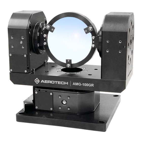
Page 1: Amg-Gr Series Gear-Driven Gimbals
AMG-GR Series Gear-Driven Gimbals HARDWARE MANUAL Revision 2.00... - Page 2 Global Technical Support Portal for information and support about your Aerotech, Inc. products. The website supplies software, product manuals, Help files, training schedules, and PC-to-PC remote technical support. If necessary, you can complete Product Return (RMA) forms and get information about repairs and spare or replacement parts.
-
Page 3: Table Of Contents
Hardware Manual AMG-GR Table of Contents AMG-GR Series Gear-Driven Gimbals Table of Contents List of Figures List of Tables EU Declaration of Incorporation UKCA Declaration of Incorporation Safety Procedures and Warnings Installation and Operation Electrical Warnings Motor-Related Warnings Pinch Points Handling and Storage Chapter 1: Overview 1.1. -
Page 4: List Of Figures
Hall Phasing Diagram Figure 3-5: Encoder Phasing Reference Diagram (Standard/Square Wave) Figure 3-6: Encoder Phasing Reference Diagram (Analog/Sine Wave) Figure 4-1: Lubrication Ports Figure 4-2: View of the Current Draw of a Typical AMG-GR Stage Before and After Lubrication www.aerotech.com... -
Page 5: List Of Tables
Table 3-14: Limit Switch Specifications Table 3-15: Brake Specifications Table 3-16: Maximum Motor Bus Voltage Table 3-17: Resolution Information Table 3-18: Brushless Rotary Motor Specifications Table 3-19: Brushless, Slotless Rotary Motor Specifications Table 3-20: Stepper Motor Specifications Table 4-1: Troubleshooting www.aerotech.com... -
Page 6: Eu Declaration Of Incorporation
AMG-GR Hardware Manual EU Declaration of Incorporation Manufacturer Aerotech, Inc. 101 Zeta Drive Pittsburgh, PA 15238-2811 herewith declares that the product: AMG-GR gimbal is intended to be incorporated into machinery to constitute machinery covered by the Directive 2006/42/EC as amended;... -
Page 7: Ukca Declaration Of Incorporation
Hardware Manual AMG-GR UKCA Declaration of Incorporation Manufacturer Aerotech, Inc. 101 Zeta Drive Pittsburgh, PA 15238-2811 herewith declares that the product: AMG-GR gimbal To which this declaration relates, meets the essential health and safety requirements and is in conformity with the relevant UK Legislation listed below:... -
Page 8: Safety Procedures And Warnings
To find the newest information about this product, refer to www.aerotech.com. If you do not understand the information in this manual, contact Aerotech Global Technical Support. IMPORTANT: This product has been designed for light industrial manufacturing or laboratory environments. -
Page 9: Installation And Operation
WARNING: Trip Hazard! Route, house, and secure all cables, duct work, air, or water lines. Failure to do so could introduce trip hazards around the system that could result in physical injury or could damage the equipment. www.aerotech.com... -
Page 10: Electrical Warnings
It is the responsibility of the End User/System Integrator to make sure that stages are properly connected and grounded per Engineering Standards and applicable safety requirements. It is the responsibility of the End User/System Integrator to configure the system drive or controller within the Aerotech motor/stage electrical and mechanical specifications. www.aerotech.com... -
Page 11: Motor-Related Warnings
Hardware Manual AMG-GR Motor-Related Warnings Aerotech motors are capable of producing high forces and velocities. Obey all warnings and all applicable codes and standards when you use or operate a stage or system that incorporates Aerotech motors. DANGER: Mechanical Hazard! Personnel must be made aware of the mechanical hazards during set up or when you do service to the stage. -
Page 12: Pinch Points
(during normal operation, for example). when the system is moved manually (during the installation process or when you do maintenance, for example). Motors are capable of very high speeds and acceleration rates. Figure 1: Typical Pinch Point Locations www.aerotech.com... -
Page 13: Handling And Storage
Use a cart, dolly, or similar device to move the stage to a new location. Gently set the stage on a smooth, flat, and clean surface. Use compressed nitrogen or clean, dry, oil- free air to remove any dust or debris that has collected during shipping. www.aerotech.com... -
Page 14: Figure 1-1: Shipping Brackets
Before you operate the stage, let it stabilize at room temperature for at least 12 hours. This will ensure that all of the alignments, preloads, and tolerances are the same as they were when they were tested at Aerotech. Each stage has a label listing the system part number and serial number. These numbers contain information necessary for maintenance or system hardware and software updates. -
Page 15: Figure 1-2: Lifting Features
Store the gimbal in the original shipping container. If the original packaging included ESD protective packaging, make sure to store the gimbal in it. The storage location must be dry, free of dust, free of vibrations, and flat. Section 1.1. Environmental Specifications Refer to www.aerotech.com... - Page 16 AMG-GR Hardware Manual This page intentionally left blank. www.aerotech.com...
-
Page 17: Chapter 1: Overview
BM75 brushless servomotor with 2500-line TTL encoder and brake AMG100GR / 150GR SM35 stepper motor AMG200GR / 300GR BM75 brushless servomotor with 1000-line 1 Vpp encoder BM75 brushless servomotor with 1000-line 1 Vpp encoder and AMG200GR / 300GR brake AMG200GR / 300GR SM60 Stepper Motor www.aerotech.com... - Page 18 SM60 stepper motor Mounting Plate (Optional) Optical table mounting plate Note: -MP option required when continuous azimuth travel option is selected. Metrology (Required) -PL0 No metrology performance plots -PL1 Metrology, uncalibrated with performance plots -PL2 Metrology, calibrated (HALAR) with performance plots www.aerotech.com...
-
Page 19: Environmental Specifications
Indoor use only 1.2. Accuracy and Temperature Effects Aerotech products are designed for and built in a 20°C (68°F) environment. Temperature changes could cause a decrease in performance or permanent damage to the gimbal. At a minimum, the environmental temperature must be controlled to within 0.25ºC per 24 hours to ensure the gimbal specifications are repeatable over an extended period of time. -
Page 20: Basic Specifications
(1) Custom travels available upon request. (2) Certified with each stage. Specifications are per axis unless specified. (3) Maximum speed is load dependent. Contact an Aerotech Application Engineer if imbalanced loads are present. Requires the selection of an appropriate amplifier with sufficient voltage and current. -
Page 21: Vacuum Operation
6. To reduce outgassing during the initial pump-down to vacuum pressure, Aerotech recommends that you bake out vacuum systems when you first install them into the vacuum chamber. Bake the vacuum components at 60 °C for 24 to 48 hours to desorb water vapor from surfaces and... -
Page 22: Export Restrictions
This product is export controlled by United States Commerce Department export regulations. If you are from a non-US country and wish to make a purchase, contact Aerotech to determine if an export license is required. People in countries embargoed by the United States cannot purchase and import one of these products. -
Page 23: Chapter 2: Installation
Hardware Manual AMG-GR Chapter 2: Installation The gimbal installation must be in accordance with the instructions provided by this manual and any accompanying documentation. Failure to follow these instructions could result in injury or damage to the equipment. www.aerotech.com... -
Page 24: Dimensions
AMG-GR Hardware Manual 2.1. Dimensions Figure 2-1: AMG150GR Dimensions www.aerotech.com... -
Page 25: Figure 2-2: Amg200Gr Dimensions
Hardware Manual AMG-GR Figure 2-2: AMG200GR Dimensions www.aerotech.com... -
Page 26: Figure 2-3: Amg300Gr Dimensions
AMG-GR Hardware Manual Figure 2-3: AMG300GR Dimensions www.aerotech.com... -
Page 27: Securing The Base To The Mounting Surface
Stage Mounting Surface Flatness Requirement Stage Flatness Requirement All Frame Sizes 10 µm AMG-GR series stages have a fixed mounting pattern (refer to Figure 2-4). Refer to Section 2.1. specific model mounting locations and dimensions. Stages without the optional mounting plate have counter-bored mounting holes that are designed for 5 mm socket head cap screws (SHCS) on the AMG100GR and AMG150GR, and for 6 mm SHCS on the AMG200GR and AMG300GR. -
Page 28: Figure 2-4: View Of Amg-Gr Showing Mounting Holes
AMG-GR Hardware Manual Figure 2-4: View of AMG-GR Showing Mounting Holes www.aerotech.com... -
Page 29: Attaching The Payload To The Stage
If you start the AMG-GR without a payload, the servo gains provided by Aerotech with the shipment may not be appropriate and servo instability can occur. Refer to the controller help file for tuning assistance. - Page 30 AMG-GR Hardware Manual This page intentionally left blank. www.aerotech.com...
-
Page 31: Chapter 3: Electrical Installation
Aerotech motion control systems are adjusted at the factory for optimum performance. When the AMG-GR is part of a complete Aerotech motion control system, setup should only require that you connect the gimbal to the appropriate drive chassis with the cables provided. Labels on the system components should indicate the appropriate connections. -
Page 32: Motor And Feedback Connectors
Stages equipped with standard motors and encoders come from the factory completely wired and assembled. IMPORTANT: Refer to the other documentation accompanying your Aerotech equipment. Call your Aerotech representative if there are any questions on system configuration. IMPORTANT: If you are using standard Aerotech motors and cables, motor and encoder connection adjustments are not required. -
Page 33: Table 3-1: Motor Connector Pinout
Frame Ground (motor protective Motor Phase B Return ground) (1) With brake option only. Table 3-2: Mating Connector Part Numbers for the Motor Connector Mating Connector Aerotech P/N Third Party P/N Backshell ECK00656 Amphenol #17E-1726-2 Sockets [QTY. 4] ECK00659 ITT Cannon #DM53744-6... -
Page 34: Table 3-3: Bm/Bms Feedback Connector Pinout
Common ground Common ground Reserved Reserved Reserved Reserved Brake + (with Brake Option) Table 3-4: Mating Connector Part Numbers for the BM/BMS Feedback Connector Mating Connector Aerotech P/N Third Party P/N 25-Socket D-Connector ECK00300 FCI DB25S064TLF Backshell ECK00656 Amphenol 17E-1726-2 www.aerotech.com... -
Page 35: Table 3-5: Stepper Feedback Connector Pinout
SIN- (Encoder Sine-) Reserved Common ground Common ground Reserved Reserved Reserved Reserved Table 3-6: Mating Connector Part Numbers for the Stepper Feedback Connector Mating Connector Aerotech P/N Third Party P/N 25-Socket D-Connector ECK00300 FCI DB25S064TLF Backshell ECK00656 Amphenol 17E-1726-2 www.aerotech.com... -
Page 36: Table 3-7: 9-Pin Limit Connector (-Tr90, -Tr315, Or -Tr180 Options)
“machine negative” or “machine counter-clockwise” direction.) Reserved Common ground Reserved Reserved Table 3-8: Mating Connector Part Numbers for the Limit Connector Mating Connector Aerotech P/N Third Party P/N 9-Pin D-Connector ECK00340 FCI DE09S064TLF Backshell ECK01021 Amphenol 17E-1724-2 Table 3-9:... -
Page 37: Motor And Feedback Wiring
Hardware Manual AMG-GR 3.2. Motor and Feedback Wiring Shielded cables are required for the motor and feedback connections. Figure 3-1: Motor and Feedback Wiring (BM/BMS Motors) www.aerotech.com... -
Page 38: Figure 3-2: Motor And Feedback Wiring (Sm Motors)
AMG-GR Hardware Manual Figure 3-2: Motor and Feedback Wiring (SM Motors) www.aerotech.com... -
Page 39: Motor And Feedback Specifications
Requires external pull-up to +5 V (10 kΩ recommended) Notes: If the gimbal is driven beyond the electrical limit, it will encounter a mechanical stop. Impacting the mechanical stop could cause damage to the stage even at low speeds. www.aerotech.com... -
Page 40: Table 3-15: Brake Specifications
1. If the -TRCNT option has been purchased for the Elevation Axis, the Max Motor Bus Voltage is 80 VDC, superseding the listings above. Exception (Notes) 2. For -SM motors with Aerotech controllers, amplifier bus voltages are 2X values listed. Table 3-17: Resolution Information... -
Page 41: Table 3-18: Brushless Rotary Motor Specifications
5. Torque constant and motor constant specified at stall. 6. Maximum winding temperature is 130 °C. 7. Ambient operating temperature range 0 °C - 25 °C; consult Aerotech for performance in elevated ambient temperatures. 8. All Aerotech amplifiers are rated A ;... -
Page 42: Table 3-19: Brushless, Slotless Rotary Motor Specifications
5. All performance and electrical specifications ±10%. 6. Maximum winding temperature is 100 °C (thermistor trips at 100 °C). 7. Ambient operating temperature range 0 °C - 25 °C; consult Aerotech for performance in elevated ambient temperatures. 8. All Aerotech amplifiers are rated A ;... -
Page 43: Table 3-20: Stepper Motor Specifications
Rotor Inertia (oz·in·s ( 0.0014) (0.0042) Full Step Angle ° Accuracy ° ±0.09 ±0.09 Maximum Radial Load N (lb) 28.4 (6.3) 75.4 (17) Maximum Thrust Load N (lb) 28.4 (2.2) 14.7 (3.4) Weight kg (lb) 0.50 (1.1) 0.70 (1.6) www.aerotech.com... -
Page 44: Limits, Marker, And Machine Direction
Hardware Manual 3.4. Limits, Marker, and Machine Direction Aerotech stages are configured to have positive and negative "machine" directions. The machine direction defines the phasing of the feedback and motor signals and is dictated by the stage wiring (refer to Section 3.2.). -
Page 45: Motor And Feedback Phasing
Hardware Manual AMG-GR 3.5. Motor and Feedback Phasing Motor phase voltage is measured relative to the virtual wye common point. Figure 3-4: Hall Phasing Diagram www.aerotech.com... -
Page 46: Figure 3-5: Encoder Phasing Reference Diagram (Standard/Square Wave)
AMG-GR Hardware Manual Figure 3-5: Encoder Phasing Reference Diagram (Standard/Square Wave) Figure 3-6: Encoder Phasing Reference Diagram (Analog/Sine Wave) www.aerotech.com... -
Page 47: Chapter 4: Maintenance
Visually inspect the stage and cables. Re-tighten loose connectors. Replace or repair damaged cables. Clean the AMG-GR and any components and cables as needed. Repair any damage before operating the AMG-GR. Inspect and perform an operational check on all safeguards and protective devices. www.aerotech.com... -
Page 48: Cleaning And Lubrication
4. We recommend that you do not disassemble the stage beyond the instructions given in this manual. Proper assembly and calibration can only be done at the factory. Contact Aerotech for more information. -
Page 49: Figure 4-1: Lubrication Ports
Hardware Manual AMG-GR Figure 4-1: Lubrication Ports Figure 4-2: View of the Current Draw of a Typical AMG-GR Stage Before and After Lubrication www.aerotech.com... -
Page 50: Troubleshooting
Chapter 3: Electrical Installation and Controller documentation). Stage moves uncontrollably Motor Connections (refer to Chapter 3: Electrical Installation and the Controller documentation). Gains misadjusted (refer to the Controller documentation). Stage oscillates or squeals Encoder signals (refer to the Controller documentation). www.aerotech.com... -
Page 51: Appendix A: Warranty And Field Service
All Other Repairs - After Aerotech's evaluation, the buyer shall be notified of the repair cost. At such time the buyer must issue a valid purchase order to cover the cost of the repair and freight, or authorize the product(s) to be shipped back as is, at the buyer's expense. - Page 52 Aerotech's approval. On-site Warranty Repair If an Aerotech product cannot be made functional by telephone assistance or by sending and having the customer install replacement parts, and cannot be returned to the Aerotech service center for...
-
Page 53: Appendix B: Revision History
Hardware Manual AMG-GR Appendix B: Revision History Revision General Information 2.00 General product and manual update 1.01 Revision changes have been archived. If you need a copy of this revision, contact Aerotech Global Technical Support. 1.00 www.aerotech.com... - Page 54 AMG-GR Hardware Manual This page intentionally left blank. www.aerotech.com...
-
Page 55: Index
27,29 Directive 2006/42/EC securing stage distortion multiaxis combinations Electrical Installation packing list Electrical Warnings part number 13-14 EN 60204-1 2010 Protection Rating EN ISO 12100 2010 protective ground connection Encoder Specifications EU 2015/863 Export Restrictions red, anodized aluminum www.aerotech.com... - Page 56 Specifications Brake Encoder Hall-Effect Sensors Limit Switch Thermistor Specifications stabilizing stage stage stabilizing Storage Table of Contents Temperature Effects Thermistor Specifications Troubleshooting vacuum guidelines vacuum lubricant (Braycote 602EF) Vacuum Operation Vibration Warnings Warranty and Field Service www.aerotech.com...
Need help?
Do you have a question about the AMG-GR Series and is the answer not in the manual?
Questions and answers