Sign In
Upload
Manuals
Brands
Aerotech Manuals
Industrial Equipment
AMG-GR Series
Aerotech AMG-GR Series Equipment Manuals
Manuals and User Guides for Aerotech AMG-GR Series Equipment. We have
1
Aerotech AMG-GR Series Equipment manual available for free PDF download: Hardware Manual
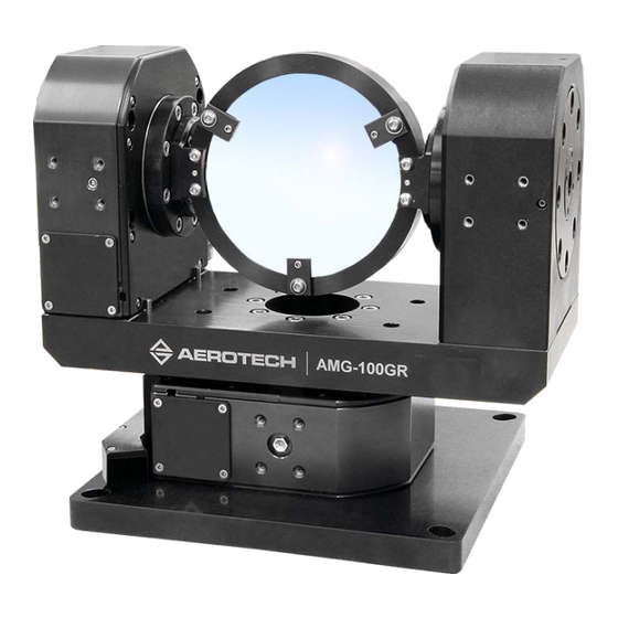
Aerotech AMG-GR Series Hardware Manual (56 pages)
Gear-Driven Gimbals
Brand:
Aerotech
| Category:
Industrial Equipment
| Size: 2.03 MB
Table of Contents
AMG-GR Series Gear-Driven Gimbals
1
Table of Contents
3
List of Figures
4
List of Tables
5
EU Declaration of Incorporation
6
UKCA Declaration of Incorporation
7
Safety Procedures and Warnings
8
Installation and Operation
9
Electrical Warnings
10
Motor-Related Warnings
11
Pinch Points
12
Handling and Storage
13
Figure 1-1: Shipping Brackets
14
Figure 1-2: Lifting Features
15
Chapter 1: Overview
17
Table 1-1: Model Numbers and Ordering Options
17
Environmental Specifications
19
Accuracy and Temperature Effects
19
Table 1-2: Environmental Specifications
19
Basic Specifications
20
Table 1-3: AMG Series Specifications
20
Vacuum Operation
21
Export Restrictions
22
Chapter 2: Installation
23
Dimensions
24
Figure 2-1: AMG150GR Dimensions
24
Figure 2-2: AMG200GR Dimensions
25
Figure 2-3: AMG300GR Dimensions
26
Securing the Base to the Mounting Surface
27
Table 2-1: Stage Mounting Surface Flatness Requirement
27
Table 2-2: Stage to Mounting Surface Hardware
27
Figure 2-4: View of AMG-GR Showing Mounting Holes
28
Attaching the Payload to the Stage
29
Chapter 3: Electrical Installation
31
Motor and Feedback Connectors
32
Table 3-1: Motor Connector Pinout
33
Table 3-2: Mating Connector Part Numbers for the Motor Connector
33
Table 3-3: BM/BMS Feedback Connector Pinout
34
Table 3-4: Mating Connector Part Numbers for the BM/BMS Feedback Connector
34
Table 3-5: Stepper Feedback Connector Pinout
35
Table 3-6: Mating Connector Part Numbers for the Stepper Feedback Connector
35
Table 3-7: 9-Pin Limit Connector (-TR90, -TR315, or -TR180 Options)
36
Table 3-8: Mating Connector Part Numbers for the Limit Connector
36
Table 3-9: 15-Pin Direct Encoder Connector (-E1, -E2, or -E3 Encoder Option)
36
Table 3-10: Mating Connector Part Numbers for the Direct Encoder Connector
36
Motor and Feedback Wiring
37
Figure 3-1: Motor and Feedback Wiring (BM/BMS Motors)
37
Figure 3-2: Motor and Feedback Wiring (SM Motors)
38
Motor and Feedback Specifications
39
Table 3-11: Hall-Effect Sensor Specifications
39
Table 3-12: Thermistor Specifications
39
Table 3-13: Encoder Specifications
39
Table 3-14: Limit Switch Specifications
39
Table 3-15: Brake Specifications
40
Table 3-16: Maximum Motor Bus Voltage
40
Table 3-17: Resolution Information
40
Table 3-18: Brushless Rotary Motor Specifications
41
Table 3-19: Brushless, Slotless Rotary Motor Specifications
42
Table 3-20: Stepper Motor Specifications
43
Limits, Marker, and Machine Direction
44
Figure 3-3: Machine Direction
44
Motor and Feedback Phasing
45
Figure 3-4: Hall Phasing Diagram
45
Figure 3-5: Encoder Phasing Reference Diagram (Standard/Square Wave)
46
Figure 3-6: Encoder Phasing Reference Diagram (Analog/Sine Wave)
46
Chapter 4: Maintenance
47
Service and Inspection Schedule
47
Cleaning and Lubrication
48
Figure 4-1: Lubrication Ports
49
Figure 4-2: View of the Current Draw of a Typical AMG-GR Stage before and after Lubrication
49
Troubleshooting
50
Table 4-1: Troubleshooting
50
Appendix A: Warranty and Field Service
51
Appendix B: Revision History
53
Index
55
Advertisement
Advertisement
Related Products
Aerotech AMG100GR
Aerotech AMG150GR
Aerotech AMG300GR
Aerotech AMG200GR
Aerotech ANT95XY-025 Series
Aerotech ABL1500WB-B Series
Aerotech ABRT-200P
Aerotech Automation1 iXI4-4P2
Aerotech APR150DR
Aerotech AGR75
Aerotech Categories
Industrial Equipment
DC Drives
Controller
Engine
Amplifier
More Aerotech Manuals
Login
Sign In
OR
Sign in with Facebook
Sign in with Google
Upload manual
Upload from disk
Upload from URL