
Related Manuals for Avalue Technology ECM-US15WP


Summary of Contents for Avalue Technology ECM-US15WP
- Page 1 ECM-US15WP 3.5" Intel® Atom™ processor Z510P / Z530P Micro Module Quick Installation Guide Ed – 11 September 2009 Part No. 2017381800R...
- Page 2 For detailed information, please always refer to the electronic user's manual. Copyright Notice Copyright © 2009 Avalue Technology Inc., ALL RIGHTS RESERVED. No part of this document may be reproduced, copied, translated, or transmitted in any form or by any means, electronic or mechanical, for any purpose, without the prior written permission of the original manufacturer.
- Page 3 Avalue Technology Inc. Room 805, Building 9,No.99 Tianzhou Rd., an Avalue Company 7 Marconi, Irvine, CA92618 Caohejing Development Area, Tel: +1-949-470-1888 Xuhui District, Shanghai Fax: +1-949-470-0971 Tel: +86-21-5169-3609 Information: BCMSales@bcmcom.com Fax:+86-21-5445-3266 Web: www.bcmcom.com Information: sales.china@avalue.com.cn Service: service@avalue.com.tw ECM-US15WP Quick Installation Guide 3...
-
Page 4: Getting Started
Before you begin installing your single board, please make sure that the following materials have been shipped: 1 x Intel® US15WP Micro Module 1 x Quick Installation Guide for ECM-US15WP 1 x SDVO to VGA daughter board 1 x DVD-ROM contains the followings: —User’s Manual (this manual in PDF file) - Page 5 Quick Installation Guide 2. Hardware Configuration ECM-US15WP Quick Installation Guide 5...
-
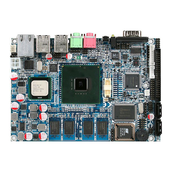
Page 6: Product Overview
ECM-US15WP Quick Installation Guide 2.1 Product Overview 6 ECM-US15WP Quick Installation Guide... -
Page 7: Jumper And Connector List
3 x 1 header, pitch 2.0mm PWR_SEL1 Serial port 1 – Ring, +5V, +12V power 3 x 1 header, pitch 2.0mm select Serial port 2 – Ring, +5V, +12V power 3 x 1 header, pitch 2.0mm select ECM-US15WP Quick Installation Guide 7... - Page 8 SATA1 SATA 2 connector SATA2 SDIO connector 5 x 1 header, pitch 2.54mm SDIO_J1 SDIO connector 6 x 1 header, pitch 2.54mm SDIO_J2 USB 2&3 connector Double deck USB1 USB 0&1 connector Double deck USB2 8 ECM-US15WP Quick Installation Guide...
-
Page 9: Setting Jumpers & Connectors
Quick Installation Guide 2.3 Setting Jumpers & Connectors 2.3.1 Clear CMOS (JABT1) Protect* Clear CMOS * Default 2.3.2 CF Card mode select (JCF1) Master * Slave * Default ECM-US15WP Quick Installation Guide 9... - Page 10 ECM-US15WP Quick Installation Guide 2.3.3 Touch Panel mode select (JTOUCH1) 4/8-Wire* 5-Wire * Default 2.3.4 AT/ATX power mode select (PWR_SEL1) AT * * Default 10 ECM-US15WP Quick Installation Guide...
- Page 11 Quick Installation Guide 2.3.5 Serial port 1 – Ring, +5V, +12V power select (RI1) Ring* +12V * Default 2.3.6 Serial port 2 – Ring, +5V, +12V power select (RI2) Ring* +12V * Default ECM-US15WP Quick Installation Guide 11...
- Page 12 ECM-US15WP Quick Installation Guide 2.3.7 ATX power connector (ATXPW1) Signal PSON- PS5VSB 2.3.8 Battery connector (BBAT1) Signal 12 ECM-US15WP Quick Installation Guide...
- Page 13 Quick Installation Guide 2.3.9 Serial Port 1 connector (COM1) Signal PIN PIN Signal 2.3.10 Serial Port 2 connector (COM2) Signal PIN PIN Signal ECM-US15WP Quick Installation Guide 13...
- Page 14 ECM-US15WP Quick Installation Guide 2.3.11 Digital Input/ Output connector (DIO1) Signal PIN PIN Signal GPI0 GPO0 GPI1 GPO1 GPI2 GPO2 GPI3 GPO3 GPI4 GPO4 GPI5 GPO5 GPI6 GPO6 GPO7 SMB_CLK SMB_DATA 14 ECM-US15WP Quick Installation Guide...
- Page 15 Primary IDE connector (IDE1) Signal PIN PIN Signal RESET# PDD7 PDD8 PDD6 PDD9 PDD5 PDD10 PDD4 PDD11 PDD3 PDD12 PDD2 PDD13 PDD1 PDD14 PDD0 PDD15 PDREQ PDIOW# PDIOR# PIORDY PDACK# IRQ15 PDA1 PDA0 PDA2 PDCS1# PDCS3# HD_LED1 ECM-US15WP Quick Installation Guide 15...
- Page 16 ECM-US15WP Quick Installation Guide 2.3.13 IrDA connector (IR1) Signal IRRX IRTX 2.3.14 Audio connector (JAUDIO1) Signal PIN PIN Signal LINEIN_L LINEIN_R LINE1-JD SPDIFO SPDIFI 16 ECM-US15WP Quick Installation Guide...
- Page 17 Quick Installation Guide 2.3.15 LCD inverter power connector (J1) Signal +12V 2.3.16 Serial port 2 in RS-422/485 mode (J422/485) Signal PIN PIN Signal 485TX- 485RX- 485TX+ 485RX+ ECM-US15WP Quick Installation Guide 17...
- Page 18 VR signal controlled by JVR1. Please see the JVR1 section for detailed circuitry information. 2.3.17.1 Signal Description – LCD Inverter Connector (JBKL1) Signal Signal Description Vadj = 0.75V ~ 4.25V (Recommended: 4.7KΩ, >1/16W) BLK_ON LCD backlight ON/OFF control signal 18 ECM-US15WP Quick Installation Guide...
- Page 19 Quick Installation Guide 2.3.18 CD-ROM audio input Connector (JCD1) Signal CD_R CD_L 2.3.19 Keyboard & mouse connector (JKB/MS) Signal Signal MSCK MSDT KBCK KBDT ECM-US15WP Quick Installation Guide 19...
- Page 20 LVDS connector (JLVDS1) Signal PIN PIN Signal LCDS_0- LCDS_0+ LCDS_1- LCDS_1+ LCDS_2- LCDS_2+ LCDS_3- LCDS_3+ LCDS_CLK- 12 11 LCDS_CLK+ I_SCL I_SDA +3.3V +3.3V Note: Mating Connector: HIROSE DF13-20DS-1.25C 2.3.21 USB 5&6 connector (JUSB1) Signal PIN PIN Signal 20 ECM-US15WP Quick Installation Guide...
- Page 21 Quick Installation Guide 2.3.22 LCD backlight brightness adjustment (JVR1) Signal 2.3.23 Power connector (PWRCON1) Signal PIN PIN Signal ECM-US15WP Quick Installation Guide 21...
- Page 22 ECM-US15WP Quick Installation Guide 2.3.24 SDIO connector (SDIO_J1) Signal +3.3V DATA1 DATA0 2.3.25 SDIO connector (SDIO_J2) Signal DATA3 DATA2 22 ECM-US15WP Quick Installation Guide...
- Page 23 Signal SENSE 2.3.27 SDVO port connector (JSDVO1) Signal PIN PIN Signal +12V SDVO_CLK SDVO_CLK# +3.3V SDVO_BLUE DVO_SEL1 SDVO_BLUE# DVO_SEL2 SDVO_GREEN SDVO_GREEN# SDVO_RED SDVO_REST SDVO_RED# SDVO_INIT SDVO_TVCLKIN SDVO_INIT# 20 SDVO_TVCLKIN# SDVO_STALL SDVO_CTRCLK SDVO_STALL# 23 24 SDVO_CTRDATA ECM-US15WP Quick Installation Guide 23...
-
Page 24: Sdvo To Dvi/ Lvds/ Crt
TLCN TDC2N YA2M YA3M TLCP TDC2P YA4P YA5P SDVO to CRT (V_VGA1) YA4M YA5M YA6P YA7P YA6M YA7M CLK1P CLK2P CLK1M CLK2M Signal PIN PIN Signal +12V +12V HS_VGA VS_VGA SDT_DDC SCK_DDC CRT_B_VGA CRT_G_VGA CRT_R_VGA 24 ECM-US15WP Quick Installation Guide...
Need help?
Do you have a question about the ECM-US15WP and is the answer not in the manual?
Questions and answers