
Related Manuals for Avalue Technology ECM-BSWA


Summary of Contents for Avalue Technology ECM-BSWA
- Page 1 ECM-BSWA Intel® Pentium®/Celeron® SoC Processor 3.5” Micro Module User’s Manual Ed – 15 February 2019 Part No. E2047394002R...
- Page 2 Disclaimer Avalue Technology Inc. reserves the right to make changes, without notice, to any product, including circuits and/or software described or contained in this manual in order to improve design and/or performance. Avalue Technology assumes no responsibility or liability for the...
- Page 3 Applications that are described in this manual are for illustration purposes only. Avalue Technology Inc. makes no representation or warranty that such application will be suitable for the specified use without further testing or modification.
- Page 4 A product returned without proof of the purchase date is not eligible for warranty service. Write the RMA number visibly on the outside of the package and ship it prepaid to your dealer. 4 ECM-BSWA User’s Manual...
-
Page 5: Table Of Contents
PC Buzzer header (JBZ1) ......................29 2.3.21 Battery connector (BT1) ......................29 2.3.22 Audio connector (JAUDIO1) ...................... 30 Signal Description – Audio connector (JAUDIO1) ..............30 2.3.22.1 2.3.23 VGA header (JVGA1) ........................ 31 2.3.24 Low pin count interface (JLPC1) ....................31 ECM-BSWA User’s Manual... - Page 6 South Bridge .......................... 53 3.6.3.2.1 Azalia Configuration ......................54 3.6.3.2.2 USB Configuration ......................... 54 3.6.4 Security ............................55 3.6.4.1 Secure Boot menu ......................... 56 3.6.4.1.1 Key Management ........................56 3.6.5 Boot .............................. 57 3.6.6 Save and exit ..........................58 6 ECM-BSWA User’s Manual...
- Page 7 Install Audio Driver (For Realtek ALC892 HD Audio) ..........62 Install LAN Driver (For Intel I211AT) ............... 63 Install Serial IO Driver ..................... 65 Install SMSC Hub Driver ..................66 Install TXE Driver ....................67 5. Mechanical Drawing ....................68 ECM-BSWA User’s Manual...
-
Page 8: Getting Started
1.2 Packing List Before you begin installing your single board, please make sure that the following materials have been shipped: 1 x 3.5” ECM-BSWA Micro Module 1 x Cable set contains the followings: ... -
Page 9: Document Amendment History
User’s Manual 1.3 Document Amendment History Revision Date Comment November 2017 Avalue Initial Release April 2018 Avalue Update Packing List February 2019 Avalue Update BIOS Setup ECM-BSWA User’s Manual... -
Page 10: Manual Objectives
We strongly recommend that you study this manual carefully before attempting to set up ECM-BSWA or change the standard configurations. Whilst all the necessary information is available in this manual we would recommend that unless you are confident, you contact your supplier for guidance. -
Page 11: System Specifications
HDMI mode: 1920 x 1080@60Hz Resolution LVDS mode: 1920 x 1080@60Hz VGA by pin header Triple Display HDMI+LVDS+VGA HDMI HDMI x1.4b Dual channel 18/24-bit LVDS Interface LVDS via (via 7511B) Audio AC97 Codec Realtek ALC892 HD codec Supports 5.1-CH Audio ECM-BSWA User’s Manual 11... - Page 12 -40°C ~ 75°C Operating 0% ~ 90% relative humidity, non-condensing Humidity Size (L x W) 5.7" x 4" (146mm x 101mm) Weight 0.44lbs (0.2kg) OS support Windows 10/Windows 7/Linux Note: Specifications are subject to change without notice. 12 ECM-BSWA User’s Manual...
-
Page 13: Architecture Overview-Block Diagram
User’s Manual 1.6 Architecture Overview—Block Diagram The following block diagram shows the architecture and main components of ECM-BSWA. ECM-BSWA User’s Manual 13... -
Page 14: Hardware Configuration
ECM-BSWA User’s Manual 2. Hardware Configuration 14 ECM-BSWA User’s Manual... -
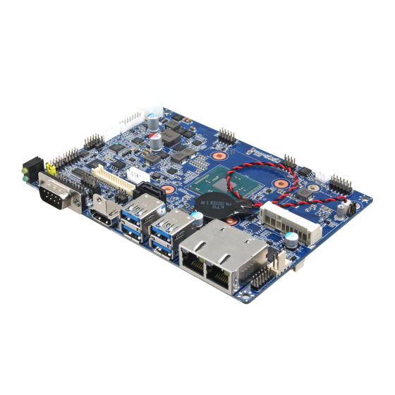
Page 15: Product Overview
User’s Manual 2.1 Product Overview ECM-BSWA User’s Manual 15... - Page 16 ECM-BSWA User’s Manual 16 ECM-BSWA User’s Manual...
-
Page 17: Jumper And Connector List
2 x 1 wafer, pitch 1.25 mm CPU fan connector 4 x 1 wafer, pitch 2.54 mm CPU_FAN1 Audio connector 6 x 2 header, pitch 2.00 mm JAUDIO1 LCD inverter connector 5 x 1 wafer, pitch 2.00 mm JBKL1 ECM-BSWA User’s Manual 17... - Page 18 8 x 2 wafer, pitch 2.00 mm JSPI1 BIOS SPI header 4 x 2 header, pitch 2.00 mm JBZ1 PC Buzzer header 2 x 1 wafer, pitch 2.00 mm HDMI1 HDMI connector MINI_PCIE1/2 Mini-PCI connector 1/2 SO_DIMM1 DDR3 SODIMM connector 18 ECM-BSWA User’s Manual...
-
Page 19: Setting Jumpers & Connectors
User’s Manual 2.3 Setting Jumpers & Connectors 2.3.1 AT/ATX Input power select (JAT1) * Default 2.3.2 Serial port 1 pin9 signal select (JRI1) Ring* +12V * Default ECM-BSWA User’s Manual 19... -
Page 20: Clear Cmos (Jpcmos1)
ECM-BSWA User’s Manual 2.3.3 Clear CMOS (JPCMOS1) Protect* Clear CMOS * Default 2.3.4 LCD backlight brightness adjustment (JBKL_SEL1) PWM* * Default 20 ECM-BSWA User’s Manual... -
Page 21: Lcd Inverter Connector (Jbkl1)
User’s Manual 2.3.5 LCD Inverter connector (JBKL1) Signal VBRIGHT BKLEN +12V 2.3.6 CPU fan connector (CPU_FAN1) Signal +12V EC_TACH0 FAN_PWM0 ECM-BSWA User’s Manual 21... -
Page 22: Serial Port 1 Connector (Com1)
ECM-BSWA User’s Manual 2.3.7 Serial port 1 connector (COM1) Signal PIN PIN Signal 2.3.8 Serial port 2/6 connector (JCOM2/JCOM 6) JCOM2 JCOM6 Signal PIN PIN Signal NDCD# NRXD NTXD NDTR# NDSR# NRTS# NCTS# NRI# 22 ECM-BSWA User’s Manual... -
Page 23: Serial Port 3/4/5 Connector (Jcom3/Jcom4/Jcom5)
Serial port 3/4/5 connector (JCOM3/JCOM4/JCOM5) JCOM5 JCOM4 JCOM3 Signal PIN PIN Signal NDCD# NRXD NTXD NDTR# NDSR# NRTS# NCTS# NRI# 2.3.10 Serial port 2 in RS-422/485 mode (J422_485) Signal PIN PIN Signal 485TX2- 485RX2- 485TX2+ 485RX2+ ECM-BSWA User’s Manual 23... -
Page 24: General Purpose I/O Connector (Jdio1)
ECM-BSWA User’s Manual 2.3.11 General purpose I/O connector (JDIO1) Signal PIN PIN Signal DIO_GP20 DIO_GP10 DIO_GP21 DIO_GP11 DIO_GP22 DIO_GP12 DIO_GP23 DIO_GP13 SMB_CLK_MAIN 10 SMB_DATA_MAIN 2.3.12 Touch Panel connector (JTOUCH1) Signal THX+ THX- THPROBE_R THY+ THY- 24 ECM-BSWA User’s Manual... -
Page 25: Sata Power Header (Sata_Pwr1)
User’s Manual 2.3.13 SATA Power header (SATA_PWR1) Signal SATA_PWR 2.3.14 Power connector (PWR1) Signal Signal +26V +26V ECM-BSWA User’s Manual 25... -
Page 26: Ec Debug Connector (Jec_Rom1)
ECM-BSWA User’s Manual 2.3.15 EC Debug connector (JEC_ROM1) Signal EC_SMBCLK EC_SMBDATA 2.3.16 On-board header for USB2.0 (H_JUSB1) Signal PIN PIN Signal USBVCC_HSIC12 HSIC_DN_2 HSIC_DP_2 HSIC_DP_1 HSIC_DN_1 10 USBVCC_HSIC12 26 ECM-BSWA User’s Manual... -
Page 27: Lvds Connector (Jlvds1)
LVDS_DATA0_P 10 LVDS_DATA1_P LVDS_DATA0_N 12 11 LVDS_DATA1_N LVDS_DATA2_P 16 15 LVDS_DATA3_P LVDS_DATA2_N 18 17 LVDS_DATA3_N LVDS_DATA4_P 22 21 LVDS_DATA5_P LVDS_DATA4_N 24 23 LVDS_DATA5_N LVDS_DATA6_P 28 27 LVDS_DATA7_P LVDS_DATA6_N 30 29 LVDS_DATA7_N LVDS_CLK1_P LVDS_CLK2_P LVDS_CLK1_N LVDS_CLK2_N +12V +12V ECM-BSWA User’s Manual 27... -
Page 28: Miscellaneous Setting Connector (Jfp1)
ECM-BSWA User’s Manual 2.3.18 Miscellaneous setting connector (JFP1) Signal PWBT RST# PWR-LED+ PWR-LED- HDD-LED- HDD-LED+ 2.3.19 BIOS SPI header (JSPI1) Signal PIN PIN Signal SPI_HOLD# SPI_MOSI SPI_MISO CPI_CLK SPI_CS#0 +1.8VSB 28 ECM-BSWA User’s Manual... -
Page 29: Pc Buzzer Header (Jbz1)
User’s Manual 2.3.20 PC Buzzer header (JBZ1) Signal SOC_SPKR_R 2.3.21 Battery connector (BT1) Signal +RTCBATT ECM-BSWA User’s Manual 29... -
Page 30: Audio Connector (Jaudio1)
LINE1-JD FRONT-JD MIC1-L-IN MIC1-R-IN LIN1-L-IN LINE1-R-IN HD_AGND HD_AGND FRONT-L-OUT FRONT-R-OUT 2.3.22.1 Signal Description – Audio connector (JAUDIO1) Signal Signal Description LINE1-JD AUDIO IN (LINE_RIN/LIN)sense pin FRONT-JD AUDIO Out(ROUT/LOUT) sense pin MIC1-JD MIC IN (MIC_RIN/LIN) sense pin 30 ECM-BSWA User’s Manual... -
Page 31: Vga Header (Jvga1)
User’s Manual 2.3.23 VGA header (JVGA1) Signal PIN PIN Signal VGA_RED VGA_GREEN VGA_BLUE VGA_DDCDAT VGA_HSYNC_R VGA_VSYNC_R VGA_DDCCLK 2.3.24 Low pin count interface (JLPC1) Signal PIN PIN Signal LPC_AD0 +3.3V LPC_AD1 PLT_RST# LPC_AD2 LPC_FRAME# LPC_AD3 LPC_CLK_DEB LPC_SERIRQ ECM-BSWA User’s Manual 31... -
Page 32: Bios Setup
ECM-BSWA User’s Manual 3.BIOS Setup 32 ECM-BSWA User’s Manual... -
Page 33: Introduction
If you do not press the keys at the correct time and the system does not boot, an error message will be displayed and you will again be asked to. Press F1 to Continue, DEL to enter SETUP ECM-BSWA User’s Manual 33... -
Page 34: Using Setup
Note: Some of the navigation keys differ from one screen to another. To Display a Sub Menu Use the arrow keys to move the cursor to the sub menu you want. Then press <Enter>. A “” pointer marks all sub menus. 34 ECM-BSWA User’s Manual... -
Page 35: Getting Help
BIOS Vendor and your systems manufacturer to provide the absolute maximum performance and reliability. Even a seemingly small change to the chipset setup has the potential for causing you to use the override. ECM-BSWA User’s Manual 35... -
Page 36: Bios Setup
<Enter> to accept and enter the sub-menu. 3.6.1 Main Menu This section allows you to record some basic hardware configurations in your computer and set the system clock. 36 ECM-BSWA User’s Manual... -
Page 37: System Language
Visit the Avalue website (www.avalue.com.tw) to download the latest product and BIOS information. 3.6.2 Advanced Menu This section allows you to configure your CPU and other system devices for basic operation through the following sub-menus. ECM-BSWA User’s Manual 37... -
Page 38: Apci Settings
Disabled[Default], ErP Function ErP Function (Deep S5). Enabled Off[Default] Pwr-On After PWR-Fail AC loss resume. Last state Disabled[Default], 30 sec 40 sec 50 sec Watch Dog Select WatchDog. 1 min 2 min 10 min 30 min 38 ECM-BSWA User’s Manual... -
Page 39: It8528 Super Io Configuration
Set Parameters of Serial Port 3 (COMC). Serial Port 4 Configuration Set Parameters of Serial Port 4 (COMD). Serial Port 5 Configuration Set Parameters of Serial Port 5 (COME). Serial Port 6 Configuration Set Parameters of Serial Port 6 (COMF). ECM-BSWA User’s Manual 39... -
Page 40: Serial Port 1 Configuration
3.6.2.2.1 Serial Port 1 Configuration Item Option Description Disabled Serial Port Enable or Disable Serial Port (COM). Enabled[Default] Auto[Default] IO=3F8h; IRQ=4; IO=3F8h; IRQ=3,4,5,6,7,9,10,11,12; Select an optimal setting for Super Change Settings IO=2F8h; IRQ=3,4,5,6,7,9,10,11,12; IO Device. IO=3E8h; IRQ=3,4,5,6,7,9,10,11,12; IO=2E8h; IRQ=3,4,5,6,7,9,10,11,12; 40 ECM-BSWA User’s Manual... -
Page 41: Serial Port 2 Configuration
IO=2F8h; IRQ=3; IO=3F8h; IRQ=3,4,5,6,7,9,10,11,12; Select an optimal setting for Super Change Settings IO=2F8h; IRQ=3,4,5,6,7,9,10,11,12; IO Device. IO=3E8h; IRQ=3,4,5,6,7,9,10,11,12; IO=2E8h; IRQ=3,4,5,6,7,9,10,11,12; UART 232[Default] Change the Serial Port as UART 232 422 485 UART 422 RS232/422/485. UART 485 ECM-BSWA User’s Manual 41... -
Page 42: Serial Port 3 Configuration
3.6.2.2.3 Serial Port 3 Configuration Item Option Description Disabled Serial Port Enable or Disable Serial Port (COM). Enabled[Default] Auto[Default] IO=3E8h; IRQ=10; IO=3F8h; IRQ=3,4,5,6,7,10,11,12; Select an optimal setting for Super Change Settings IO=2F8h; IRQ=3,4,5,6,7,10,11,12; IO Device. IO=3E8h; IRQ=3,4,5,6,7,10,11,12; IO=2E8h; IRQ=3,4,5,6,7,10,11,12; 42 ECM-BSWA User’s Manual... -
Page 43: Serial Port 4 Configuration
Disabled Serial Port Enable or Disable Serial Port (COM). Enabled[Default] Auto[Default] IO=2E8h; IRQ=11; IO=3F8h; IRQ=3,4,5,6,7,10,11,12; Select an optimal setting for Super Change Settings IO=2F8h; IRQ=3,4,5,6,7,10,11,12; IO Device. IO=3E8h; IRQ=3,4,5,6,7,10,11,12; IO=2E8h; IRQ=3,4,5,6,7,10,11,12; 3.6.2.2.5 Serial Port 5 Configuration ECM-BSWA User’s Manual 43... -
Page 44: Serial Port 6 Configuration
Enable or Disable Serial Port (COM). Enabled[Default] 3.6.2.2.6 Serial Port 6 Configuration Item Option Description Disabled Serial Port Enable or Disable Serial Port (COM). Enabled[Default] 3.6.2.3 H/W Monitor Item Options Description Enabled, Smart Fan Function Enables or Disables Smart Fan. Disabled[Default] 44 ECM-BSWA User’s Manual... -
Page 45: S5 Rtc Wake Settings
Wake system from S5 Fixed Time Select Dynamic Time, System will wake on the current time Dynamic Time + Increase minute(s). 3.6.2.5 CPU Configuration Use the CPU configuration menu to view detailed CPU specification and configure the CPU. ECM-BSWA User’s Manual 45... -
Page 46: Socket 0 Cpu Information
EIST Enable/Disable Intel SpeedStep. Enabled[Default] Disabled Turbo Mode Turbo Mode. Enabled[Default] HW_ALL[Default] P-STATE Coordination SW_ALL Change P-STATE Coordination type. SW_ANY HW_ALL[Default] Package C State limit SW_ALL Change P-STATE Coordination type. SW_ANY 3.6.2.5.1 Socket 0 CPU Information 46 ECM-BSWA User’s Manual... -
Page 47: Sata Configuration
SATA Mode Selection AHCI[Default] Determines how SATA controller operate. Gen1 Select SATA Interface Speed, CHV A1 always with SATA Interface Speed Gen2 Gen 1 Speed. Gen3[Default] Disabled Port 0/1 Enable/Disable SATA Port. Enabled[Default] 3.6.2.7 Network Stack Configuration ECM-BSWA User’s Manual 47... -
Page 48: Csm Configuration
Use Win10: CSM support setting ”Disabled”. Use Win7: CSM support setting ”Enabled”. Item Options Description Disabled CSM Support Enable/Disable CSM Support. Enabled[Default] UPON REQUEST – GA20 can be disabled Upon Request GateA20 Active using BIOS services. ALWAYS – do not Always[Default] 48 ECM-BSWA User’s Manual... -
Page 49: Usb Configuration
The USB Configuration menu helps read USB information and configures USB settings. Item Options Description Enables Legacy USB support. AUTO option Enabled[Default] disables legacy support if no USB devices are Legacy USB Support Disabled connected. DISABLE option will keep USB Auto devices available only for EFI applications. ECM-BSWA User’s Manual 49... -
Page 50: Chipset
Floppy enumerates devices according to their media format. Optical drives are emulated as ‘CDROM’, Mass Storage Devices Forced FDD Hard Disk drives with no media will be emulated according CD-ROM to a drive type. 3.6.3 Chipset 50 ECM-BSWA User’s Manual... -
Page 51: North Bridge
Select which of IGD/PCI Graphics Primary Display device should be Primary Display. PCIe Enabled, GFX Boost Enable/Disable GFX Boost. Disabled[Default] 32M[Default]/64M/96M128M/160M Select DVMT 5.0 Pre-Allocated DVMT Pre-Allocated /192M/224M/256M/288M/320M/352M/ (Fixed) Graphics Memory size used 384M/416M/448M/480M/512M by the Internal Graphics Device. ECM-BSWA User’s Manual 51... -
Page 52: Igd - Lcd Control
1920x1080 18/2 1280x1024 24/2 1440x900 18/2 1600x1200 24/2 1366x768 24/1 1920x1080 24/2 1680x1050 24/2 BIOS[Default] LVDS Brightness Control Method. 1.BIOS Brightness Control Method OS Driver 2.OS Driver. LVDS Back Light PWM Select LVDS back light PWM duty. 52 ECM-BSWA User’s Manual... -
Page 53: South Bridge
Select LVDS back light PWM Frequency. Frequency Enabled[Default] USB Touch Enable or Disable USB Touch. Disabled Enabled[Default] CH7517 VGA Enable or Disable CH7517 VGA. Disabled 3.6.3.2 South Bridge Item Option Description Disabled[Default] Wake On Ring Enable/Disable Wake On Ring. Enabled ECM-BSWA User’s Manual 53... -
Page 54: Azalia Configuration
Azalia will be unconditionally disabled. Enabled = Disabled Azalia will be unconditionally Enabled. 3.6.3.2.2 USB Configuration Item Option Description Enabled[Default], XHCI Mode Mode of operation of xHCI controller. Disabled Enabled[Default], USB Standby Power Setting Enabled/Disabled USB Standby Power. Disabled 54 ECM-BSWA User’s Manual... -
Page 55: Security
User’s Manual 3.6.4 Security Administrator Password Set setup Administrator Password User Password Set User Password ECM-BSWA User’s Manual 55... -
Page 56: Secure Boot Menu
User mode with enrolled Platform Key(PK) 2. CSM Enabled function is disabled. Secure Boot mode selector. ‘Custom’ Mode enables Standard Secure Boot Mode users to change Image Execution policy and manage Custom[Default] Secure Boot Keys. 3.6.4.1.1 Key Management 56 ECM-BSWA User’s Manual... -
Page 57: Boot
Setup Prompt Timeout 1~ 65535 key. 65535(0xFFFF) means indefinite waiting. On[Default] Bootup NumLock State Select the Keyboard NumLock state Disabled[Default] Quiet Boot Enables or disables Quiet Boot option Enabled Boot Option #1 Set the system boot order. ECM-BSWA User’s Manual 57... -
Page 58: Save And Exit
This option restores all BIOS settings to the factory default. This option is useful if the controller exhibits unpredictable behavior due to an incorrect or inappropriate BIOS setting. 3.6.6.4 Launch EFI Shell from filesystem device Attempts to Launch EFI Shell application (Shellx64.efi) from one of the available filesystem devices. 58 ECM-BSWA User’s Manual... -
Page 59: Drivers Installation
User’s Manual 4. Drivers Installation Note: Installation procedures and screen shots in this section are for your reference and may not be exactly the same as shown on your screen. ECM-BSWA User’s Manual 59... -
Page 60: Install Chipset Driver
Windows 10 operation system. If the warning message appears while the installation process, click Continue to go on. Step 3. Click Install. Step 4. Click Finish to complete setup. Step1. Click Next. Step 2. Click Accept. 60 ECM-BSWA User’s Manual... -
Page 61: Install Vga Driver
Windows 10 operation system. Step 3. Click Next. Step 1. Click Next to continue installation. Step 4. Click Next. Step 2. Step 5. Click Finish to complete setup. Click Yes to accept license agreement. ECM-BSWA User’s Manual 61... -
Page 62: Install Audio Driver (For Realtek Alc892 Hd Audio)
Windows 10 operation system. If the warning message appears while the installation process, click Continue to go on. Step1. Click Next to Install. Step 2. Select Finish to complete Installation. 62 ECM-BSWA User’s Manual... -
Page 63: Install Lan Driver (For Intel I211At)
Windows 10 operation system. Step 3. Click Next. Step 4. Click Install. Step 1. Click Next to continue installation. Step 2. Click Next. Step 5. Wait while installing. ECM-BSWA User’s Manual 63... - Page 64 ECM-BSWA User’s Manual Step 6. Click Finish to complete setup. 64 ECM-BSWA User’s Manual...
-
Page 65: Install Serial Io Driver
All drivers can be found on the Avalue Official Website: http://www.avalue.com.tw. Note: The installation procedures and screen shots in this section are based on Windows 10 operation system. Step 1. Click Next to continue setup. Step 2. Click Finish to complete the setup. ECM-BSWA User’s Manual 65... -
Page 66: Install Smsc Hub Driver
All drivers can be found on the Avalue Official Website: http://www.avalue.com.tw. Note: The installation procedures and screen shots in this section are based on Windows 10 operation system. Step 1. Click Install to continue setup. Step 2. Click Yes to complete the setup. 66 ECM-BSWA User’s Manual... -
Page 67: Install Txe Driver
Note: The installation procedures and screen shots in this section are based on Windows 10 operation system. Step 3. Click Next Step 4. Click Finish to complete the setup Step 1. Click Next to continue setup. Step 2. Click Next. ECM-BSWA User’s Manual 67... -
Page 68: Mechanical Drawing
ECM-BSWA User’s Manual 5. Mechanical Drawing 68 ECM-BSWA User’s Manual... - Page 69 User’s Manual Unit: mm ECM-BSWA User’s Manual 69...
- Page 70 ECM-BSWA User’s Manual Unit: mm 70 ECM-BSWA User’s Manual...
- Page 71 User’s Manual Unit: mm ECM-BSWA User’s Manual 71...
Need help?
Do you have a question about the ECM-BSWA and is the answer not in the manual?
Questions and answers