
Related Manuals for Avalue Technology ECM-QM77


Summary of Contents for Avalue Technology ECM-QM77
- Page 1 ECM-QM77 Intel® Ivy Bridge Processors 3.5” Micro Module with Intel® QM77 Chipset User’s manual Ed – 03 September 2013 Copyright Notice Copyright 2013 Avalue Technology Inc., ALL RIGHTS RESERVED. Part No. E2047391203R...
- Page 2 Disclaimer Avalue Technology Inc. reserves the right to make changes, without notice, to any product, including circuits and/or software described or contained in this manual in order to improve design and/or performance. Avalue Technology assumes no responsibility or liability for the...
- Page 3 Applications that are described in this manual are for illustration purposes only. Avalue Technology Inc. makes no representation or warranty that such application will be suitable for the specified use without further testing or modification.
- Page 4 Room 805, Building 9,No.99 Tianzhou Rd., 3F Ishiyama-Bldg, 1-6-1 Taito, Caohejing Development Area, Taito-ku, Tokyo 110-0016 Japan Tel : +81-3-5807-2321 Xuhui District, Shanghai Fax : +81-3-5807-2322 Tel: +86-21-5169-3609 Information : sales.japan@avalue.com.tw Fax:+86-21-5445-3266 Service : service@avalue.com.tw Information: sales.china@avalue.com.cn Service: service@avalue.com.tw 4 ECM-QM77 User’s Manual...
- Page 5 (such as your sales receipt) in a shippable container. A product returned without proof of the purchase date is not eligible for warranty service. 5. Write the RMA number visibly on the outside of the package and ship it prepaid to your dealer. ECM-QM77 User’s Manual 5...
-
Page 6: Table Of Contents
LVDS connector (JLVDS1) ...................... 32 2.4.19 On-board box header for USB3.0 (JUSB3/1) ................33 2.4.20 On-board box header for USB2.0 (JUSB1) ................33 2.4.21 PS/2 keyboard & mouse connector (JKB/ MS1) ..............34 2.4.22 HD power connector (HD_PWR1) ................... 34 6 ECM-QM77 User’s Manual... - Page 7 Serial Port 1 Configuration ................58 3.6.2.14 Hardware Monitor ....................59 3.6.2.15 Intel® Smart Connect Technology ..............60 3.6.2.16 CPU PPM Configuration ..................60 3.6.3 Chipset ........................... 61 3.6.3.1 PCH-IO Configuration ..................62 3.6.3.1.1 PCI Express Configuration ................63 ECM-QM77 User’s Manual 7...
- Page 8 Install USB 3.0 Driver (For Intel QM77) ............... 81 Install VGA Driver (For Intel QM77) ..............82 Install Audio Driver (For Realtek ALC892) ............84 Install Ethernet Driver (For Intel 82579LM and 82574L) ........85 5. Mechanical Drawing ....................87 8 ECM-QM77 User’s Manual...
-
Page 9: Getting Started
Before you begin installing your single board, please make sure that the following materials have been shipped: 1 x 3.5” ECM-QM77 Micro Module 1 x Quick Installation Guide for ECM-QM77 1 x AUX-056 daughter board 1 x DVD-ROM contains the followings: ... -
Page 10: Document Amendment History
ECM-QM77 1.3 Document Amendment History Revision Date Comment October 2012 Initial Release December 2012 Connector List Update January 2013 Increase Installing the CPU September 2013 Update Mechanical Drawing 10 ECM-QM77 User’s Manual... -
Page 11: Manual Objectives
We strongly recommend that you study this manual carefully before attempting to interface with ECM-QM77 series or change the standard configurations. Whilst all the necessary information is available in this manual we would recommend that unless you are confident, you contact your supplier for guidance. -
Page 12: System Specifications
Realtek ALC892 Supports 7.1-CH Audio Audio Interface Mic-in, Line-in, Line-out Ethernet 1 x Intel® 82574L Gigabit Ethernet LAN Chip 1 x Intel® 82579 Gigabit Ethernet Ethernet Interface 10/ 100/ 1000 Base-Tx Gigabit Ethernet Compatible Mechanical & Environmental 12 ECM-QM77 User’s Manual... - Page 13 AT/ATX Operating Temp. 0 ~ 60°C (32 ~ 140°F) Storage -40 ~ 75°C (-40 ~ 167°F) Temperature Operating Humidity 0%~90% Relative Humidity, Non-condensing Size (L x W) 5.7" x 4" (146mm x 101mm) Weight 0.44lbs (0.2kg) ECM-QM77 User’s Manual 13...
-
Page 14: Architecture Overview - Block Diagram
ECM-QM77 1.6 Architecture Overview – Block Diagram The following block diagram shows the architecture and main components of ECM-QM77. 14 ECM-QM77 User’s Manual... -
Page 15: Hardware Configuration
User’s Manual 2. Hardware Configuration ECM-QM77 User’s Manual 15... -
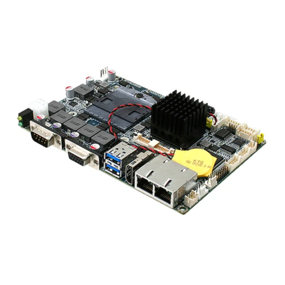
Page 16: Product Overview
ECM-QM77 2.1 Product Overview 16 ECM-QM77 User’s Manual... - Page 17 User’s Manual ECM-QM77 User’s Manual 17...
-
Page 18: Installation Procedure
Note: Make sure the heat sink and the CPU top surface are in total contact to avoid CPU overheating problem that would cause the system to hang or unstable 18 ECM-QM77 User’s Manual... -
Page 19: Main Memory
User’s Manual 2.2.1 Main Memory ECM-QM77 provides one 204-pin DDR3 SODIMM socket, supports up to 8GB DDR3 1333/1600 SDRAM. SODIMM (Rear side) Make sure to unplug the power supply before adding or removing SODIMMs or other system components. Failure to do so may cause severe damage to both the board and the components. - Page 20 (2) Static electricity can damage the electronic components of the computer or optional boards. Before starting these procedures, ensure that you are discharged of static electricity by touching a grounded metal object briefly. 20 ECM-QM77 User’s Manual...
-
Page 21: Jumper And Connector List
Clear CMOS 3 x 1 header, pitch 2.54 mm COM 1 pin 9 signal select 3 x 2 header, pitch 2.00 mm JRI1 JAT1 AT/ ATX Input power select 3 x 1 header, pitch 2.00 mm ECM-QM77 User’s Manual 21... - Page 22 Serial ATA connector 1 SATA1 SATA2 Serial ATA connector 2 SYS_FAN1 System fan connector 4 x 1 wafer, pitch 2.54 mm USB1_1 On-board connector for USB3.0 VGA1 VGA connector D-sub 15-pin, female Mini-PCI connector MPCIE1 DDR3 SODIMM connector 22 ECM-QM77 User’s Manual...
-
Page 23: Setting Jumpers & Connectors
User’s Manual 2.4 Setting Jumpers & Connectors 2.4.1 Clear CMOS (JBAT1) Protect* Clear CMOS * Default 2.4.2 COM 1 pin 9 signal select (JRI1) Ring* +12V * Default ECM-QM77 User’s Manual 23... -
Page 24: At/ Atx Input Power Select (Jat1)
ECM-QM77 2.4.3 AT/ ATX Input power select (JAT1) * Default 2.4.4 5VSB connector in ATX (PWR_SB1) Signal SIO_PSON# +ATX5VSB 24 ECM-QM77 User’s Manual... -
Page 25: Battery Connector (Bat1)
User’s Manual 2.4.5 Battery connector (BAT1) Signal +3.3V 2.4.6 CPU fan connector (CPU_FAN1) Signal +12V CPUFANIN0 CPUFANOUT0 ECM-QM77 User’s Manual 25... -
Page 26: System Fan Connector (Sys_Fan1)
2.4.7 System fan connector (SYS_FAN1) Signal +12V SYSFANIN SYSFANOUT 2.4.8 COM 1 RS-422-485 mode (J422/1) Signal PIN PIN Signal 485_422TX- 422RX- 485_422TX+ 422RX+ Note: J422/485 is available after modify the mode of COM1 in BIOS setting 26 ECM-QM77 User’s Manual... -
Page 27: Audio Connector (Jaudio1)
Signal MIC1-JD LINE1-JD FRONT-JD MIC1-L-IN MIC1-R-IN LINE1-L-IN LINE1-R-IN FRONT-L-OUT FRONT-R-OUT 2.4.9.1 Signal Description – Audio connector (JAUDIO1) Signal Signal Description LINE1_JD AUDIO IN (LINE_RIN/LIN)sense pin FRONT_JD AUDIO Out(ROUT/LOUT) sense pin MIC1_JD MIC IN (MIC_RIN/LIN) sense pin ECM-QM77 User’s Manual 27... -
Page 28: Lcd Inverter Connector (Jbkl1)
ECM-QM77 2.4.10 LCD inverter connector (JBKL1) Signal +12V BKLEN BRIADJ 2.4.11 LCD backlight brightness adjustment (JVR1) Signal BRIGHT Variation Resistor (Recommended: 4.7KΩ, >1/16W) 28 ECM-QM77 User’s Manual... -
Page 29: Low Pin Count Connector (Jlpc1)
Low pin count connector (JLPC1) Signal PIN PIN Signal LPC_AD0 +3.3V LPC_AD1 LPC_RST# LPC_AD2 LPC_FRAME# LPC_AD3 CLK_PCI_LPC INT_SERIRQ +V5S +V5A PCH_DRQ#1 2.4.13 Serial port 2 connector (JCOM2) Signal PIN PIN Signal DCD2 RxDD2 TxDD2 DTR2 DSR2 RTS2 CTS2 ECM-QM77 User’s Manual 29... -
Page 30: General Purpose I/O Connector (Jdio1)
ECM-QM77 2.4.14 General purpose I/O connector (JDIO1) Signal PIN PIN Signal SMB_DATA_9555 10 SMB_CLK_9555 DIO_GP13 DIO_GP23 DIO_GP12 DIO_GP22 DIO_GP11 DIO_GP21 DIO_GP10 DIO_GP20 2.4.15 Miscellaneous setting connector (JFP1) Signal PWBT RST# PWR-LED HDD-LED COPEN# 30 ECM-QM77 User’s Manual... -
Page 31: Spi Connector (Jspi1)
User’s Manual 2.4.16 SPI connector (JSPI1) Signal Signal HOLD# SPI_SI SPI_SO SPI_CLK SPI_CS0# +3.3V 2.4.17 Power connector (PWR1) Signal PIN PIN Signal +12V +12V ECM-QM77 User’s Manual 31... -
Page 32: Lvds Connector (Jlvds1)
ECM-QM77 2.4.18 LVDS connector (JLVDS1) Signal PIN PIN Signal +12V +12V LVDS_CLK2_N LVDS_CLK1_N LVDS_CLK2_P LVDS_CLK1_P LVDS_DATA7_N LVDS_DATA6_N LVDS_DATA7_P LVDS_DATA6_P LVDS_DATA5_N LVDS_DATA4_N LVDS_DATA5_P LVDS_DATA4_P LVDS_DATA3_N LVDS_DATA2_N LVDS_DATA3_P LVDS_DATA2_P LVDS_DATA1_N LVDS_DATA0_N LVDS_DATA1_P LVDS_DATA0_P +3.3V +3.3V 32 ECM-QM77 User’s Manual... -
Page 33: On-Board Box Header For Usb3.0 (Jusb3/1)
2.4.19 On-board box header for USB3.0 (JUSB3/1) Signal PIN PIN Signal USB3_RXN3_L USB3_RXP3_L USB3_RXN4_L USB3_RXP4_L USB3_TXN3_L USB3_TXP3_L USB3_TXN4_L USB3_TXP4_L USB_PN_Z_2 USB_PP_Z_2 USB_PN_Z_3 USB_PP_Z_3 2.4.20 On-board box header for USB2.0 (JUSB1) Signal PIN PIN Signal USB_PN_Z_5 USB_PN_Z_4 USB_PP_Z_5 USB_PP_Z_4 ECM-QM77 User’s Manual 33... -
Page 34: Ps/2 Keyboard & Mouse Connector (Jkb/ Ms1)
ECM-QM77 2.4.21 PS/2 keyboard & mouse connector (JKB/ MS1) Signal PIN PIN Signal KBCK KBDT KBVCC MSCK MSDT 2.4.22 HD power connector (HD_PWR1) Signal 34 ECM-QM77 User’s Manual... -
Page 35: Audio / Usb Daughter Board User's Guide
LINEOUT1 LINEIN1 Line in connector Phone Jack AJAUDIO1 Audio connector 6 x 2 header, pitch 2.00mm 5 x 2 header, pitch 2.00mm AJUSB2 2.00mm USB connector AJUSB3 2.00mm USB connector 10 x 2 header, pitch 2.00mm ECM-QM77 User’s Manual 35... -
Page 36: Setting Jumper And Connector
AUSB_PN2 AUSB_PN1 AUSB_PP2 AUSB_PP1 ALINE1-L-IN ALINE1-R-IN AMIC1-L-IN AMIC1-R-IN ALINE1-JD AFRONT1-JD AMIC1-JD 2.00mm USB Connector (AJUSB3) Signal PIN PIN Signal AUSBVCC2 AUSB3_RXN1_L AUSBVCC3 AUSB3_RXP1_L 18 AUSB3_RXN2_L 17 AUSB3_RXP2_L AUSB3_TXN1_L AUSB3_TXP1_L 15 AUSB3_TXN2_L AUSB3_TXP2_L AUSB_PN3 AUSB_PP3 AUSB_PN4 AUSB_PP4 36 ECM-QM77 User’s Manual... -
Page 37: Installing The Cpu
User’s Manual 2.6 Installing the CPU 2.6.1 Locate the CPU socket on the board. Before installing the CPU, make sure that the socket box is facing towards you and the load lever is on your left. ECM-QM77 User’s Manual 37... -
Page 38: Separate Cpu Cooler And Its Base First By Screw Drawer
Separate CPU cooler and its base first by screw drawer 1. Position the CPU over the socket, making sure that the gold triangle is the same side as CPU Socket triangle CPU Socket triangle Gold triangle 38 ECM-QM77 User’s Manual... - Page 39 CPU lock clockwise to lock CPU The CPU fits in only one correct orientation. DO NOT force the CPU into the socket to prevent bending the connectors on the socket and damaging the CPU! ECM-QM77 User’s Manual 39...
-
Page 40: Bios Setup
ECM-QM77 3. BIOS Setup 40 ECM-QM77 User’s Manual... -
Page 41: Introduction
If you do not press the keys at the correct time and the system does not boot, an error message will be displayed and you will again be asked to. Press F1 to Continue, DEL to enter SETUP ECM-QM77 User’s Manual 41... -
Page 42: Using Setup
Note: Some of the navigation keys differ from one screen to another. To Display a Sub Menu Use the arrow keys to move the cursor to the sub menu you want. Then press <Enter>. A “” pointer marks all sub menus. 42 ECM-QM77 User’s Manual... -
Page 43: Getting Help
Award and your systems manufacturer to provide the absolute maximum performance and reliability. Even a seemingly small change to the chipset setup has the potential for causing you to use the override. ECM-QM77 User’s Manual 43... -
Page 44: Bios Setup
Use the arrow keys to select among the items and press <Enter> to accept and enter the sub-menu. 3.6.1 Main Menu This section allows you to record some basic hardware configurations in your computer and set the system clock. 44 ECM-QM77 User’s Manual... -
Page 45: System Language
Visit the Avalue website (www.avalue.com.tw) to download the latest product and BIOS information. 3.6.2 Advanced Menu This section allows you to configure your CPU and other system devices for basic operation through the following sub-menus. ECM-QM77 User’s Manual 45... -
Page 46: Apci Settings
Select ACPI sleep state the system APCI Sleep State S1 only(CPU Stop Clock) will enter when the SUSPEND button S3 only(Suspend to RAM)[Default] is pressed. Disabled[Default] S3 Video Repost Enable or Disable S3 Video Repost. Enabled 3.6.2.2 S5 RTC Wake Settings 46 ECM-QM77 User’s Manual... -
Page 47: Trusted Computing
+ Increase minute(s). 3.6.2.3 Trusted Computing Item Options Description Enables or Disables BIOS support for security Disable[Default], device. O.S will not show Security Device. Security Device Support Enable TCG EFI protocol and INT1A interface will not be available. ECM-QM77 User’s Manual 47... -
Page 48: Cpu Configuration
OS (Windows Server 2003 SP1, Enabled[Default] Windows XP SP2, SuSE Linux 9.2, RedHat Enterprise 3 Update 3.) When enabled, a VMM can utilize the Disabled[Default] Intel Virtualization Technology additional hardware capabilities provided by Enabled Vanderpool Technology. 48 ECM-QM77 User’s Manual... -
Page 49: Sata Configuration
Item Options Description Enabled[Default] SATA Controller(s) Enable or disable SATA Device. Disabled IDE[Default] SATA Mode Selection AHCI Determines how SATA controller(s) operate. RAID Enabled SATA Test Mode Enable or disable Test Mode. Disabled[Default] 3.6.2.6 Thermal Configuration ECM-QM77 User’s Manual 49... - Page 50 PCH Thermal Device Enable or Disable PCH Thermal Device (D31:F6) Disabled, PCH Temp Read PCH Temperature Read Enable Enabled[Default] Disabled, CPU Energy Read CPU Energy Read Enable Enabled[Default] Disabled, CPU Temp Read CPU Temperature Read Enable Enabled[Default] 50 ECM-QM77 User’s Manual...
-
Page 51: Intel(R) Rapid Start Technology
Disabled, Alert Enable Lock Lock all Alert Enable settings Enabled[Default] Disabled[Default], PCH Alert PCH Alert pin enable Enabled Disabled[Default], DIMM Alert DIMM Alert pin enable Enabled 3.6.2.7 Intel(R) Rapid Start Technology 3.6.2.8 Intel TXT (LT) Configuration ECM-QM77 User’s Manual 51... -
Page 52: Pch-Fw Configuration
Options Description Disabled[Default] MDES BIOS Status Code Enable/Disable MDES BIOS Status Code. Enabled Firmware Update Configuration Configure Management Engine Technology Parameters. Item Options Description Enable/Disable Me FW Image Re-Flash Disabled[Default] Me FW Image Re-Flash function. Enabled 52 ECM-QM77 User’s Manual... -
Page 53: Intel(R) Anti-Theft Technology Configuration
Intel(R) Anti-Theft Technology Disabled[Default] only Intel(R) Anti-Theft Technology Set the number of times Recovery attemped 1 ~ 64 Recovery will be allowed Enabled Request that platform enter Intel(R) AT Enter Intel(R) AT Suspend Mode Disabled[Default] Suspend Mode ECM-QM77 User’s Manual 53... -
Page 54: Amt Configuration
Active Remote Assistance Trigger CIRA boot. Process Enabled[Default] USB Configure Enable/Disable USB Configure function. Disabled Enabled[Default] User can Enable/Disable PET Events PET Progress Disabled progress to recieve PET events or not.. Enabled WatchDog Enable/Disable WatchDog Timer. Disabled[Default] 54 ECM-QM77 User’s Manual... -
Page 55: Usb Configuration
Maximum time the device will take before it properly reports itself to the Host Controller. Auto[Default] ‘Auto’ uses default value: for a Root port it is Device power-up delay Manual 100ms, for a Hub port the delay is taken form Hub descriptor. ECM-QM77 User’s Manual 55... -
Page 56: Super Io Configuration
(G3 state) Disabled[Default] 30 sec 40 sec 50 sec Watch Dog Set SIO watch dog timer. 60 sec 2 min 10 min 30 min Enabled ERP Deep S5 Deep S5 for power saving. Disabled[Default] 56 ECM-QM77 User’s Manual... -
Page 57: Serial Port 0 Configuration
IO=3F8h; IRQ=3,4,5,6,7,9,10,11,12 Select an optimal setting for Change Settings IO=2F8h; IRQ=3,4,5,6,7,9,10,11,12 Super IO device. IO=3E8h; IRQ=3,4,5,6,7,9,10,11,12 IO=2E8h; IRQ=3,4,5,6,7,9,10,11,12 UART 232[Default], Change the Serial Port as UART 232 422 485 UART 422, RS232/ 422/ 485 UART 485 ECM-QM77 User’s Manual 57... -
Page 58: Serial Port 1 Configuration
3.6.2.13.2 Serial Port 1 Configuration Item Option Description Enabled, Enable or Disable Serial Port Serial Port Disabled[Default] (COM) Auto[Default] IO=2F8h; IRQ=3 IO=3F8h; IRQ=3,4,5,6,7,9,10,11,12 Select an optimal setting for Change Settings IO=2F8h; IRQ=3,4,5,6,7,9,10,11,12 super IO device. IO=3E8h; IRQ=3,4,5,6,7,9,10,11,12 IO=2E8h; IRQ=3,4,5,6,7,9,10,11,12 58 ECM-QM77 User’s Manual... -
Page 59: Hardware Monitor
The following system temperature, fan speed and voltage are monitored. Temperature: System Temperature CPU Thermistor Temperature Fan Speed: System Fan Speed CPU Fan speed Voltage: VCORE +12V +5VSB AVCC 3VCC VSB3 VBAT ECM-QM77 User’s Manual 59... -
Page 60: Intel® Smart Connect Technology
ECM-QM77 3.6.2.15 Intel® Smart Connect Technology Item Description Enabled ISCT Configuration Enable/Disable ISCT Configuration. Disabled[Default] 3.6.2.16 CPU PPM Configuration 60 ECM-QM77 User’s Manual... -
Page 61: Chipset
Time window which the long duration power is maintained. Short duration power limit Short duration power limit in Watts, 0 means use factory default. Disabled[Default] Enable/Disable ACPI T state ACPI T State Enabled support. 3.6.3 Chipset ECM-QM77 User’s Manual 61... -
Page 62: Pch-Io Configuration
(The Wake Wake on LAN (PHY) Enabled[Default] On LAN cannot be disabled if ME is on at Sx state.) Disabled Enable or Disable the High High Precision Timer Enabled[Default] Precision Event Timer. 62 ECM-QM77 User’s Manual... -
Page 63: Pci Express Configuration
PCI Express Root Port 1 PCI Express Root Port 1 Settings. PCI Express Root Port 6 PCI Express Root Port 6 Settings. PCI Express Root Port 7(82574 Lan) PCI Express Root Port 7 Settings. 3.6.3.1.1.1 PCI Express Root Port 1 ECM-QM77 User’s Manual 63... -
Page 64: Pci Express Root Port 6
AUTO-BIOS auto configure: L0sL1 DISABLE-Disables ASPM. Auto[Default] Auto[Default] PCIe Speed Gen1 Select PCI Express port speed. Gen2 Disabled[Default] Detect Non-Compliance PCI Detect Non-Compliance Device Enabled Express Device, If enable, it will take more time at POST time. 64 ECM-QM77 User’s Manual... -
Page 65: Pci Express Root Port 7(82574 Lan)
L0s State: AUTO-BIOS auto L0sL1 configure: DISABLE-Disables ASPM. Auto[Default] Auto[Default] PCIe Speed Gen1 Select PCI Express port speed. Gen2 Detect Non-Compliance PCI Express Disabled[Default] Detect Non-Compliance Device Device, If enable, it will take more time Enabled at POST time. ECM-QM77 User’s Manual 65... -
Page 66: Usb Configuration
Primary Stream Array Size. Control the USB EHCI (USB 2.0) Disabled EHCI1/2 functions. One EHCI controller Enabled[Default] must always be enabled. Disabled[Default] Control each of the USB ports USB Ports Per-Port Disable Control Enabled (0~13) disabling. 66 ECM-QM77 User’s Manual... -
Page 67: Pch Azalia Configuration
User’s Manual 3.6.3.1.3 PCH Azalia Configuration Item Option Description Disabled Enable or disable internal HDMI Azalia HDMI codec Port C Enabled[Default] codec Port for Azalia. 3.6.3.2 System Agent (SA) Configuration ECM-QM77 User’s Manual 67... -
Page 68: Memory Configuration
Memory Configuration Parameters. GT – Power Management Control GT – Power Management Control Options. 3.6.3.2.1 Memory Configuration Item Option Description Auto[Default] 1067 1333 1600 Maximum Memory Frequency Memory Frequency Limiter 1867 Selections in Mhz. 2133 2400 2667 68 ECM-QM77 User’s Manual... -
Page 69: Gt - Power Management Control
GT – Power Management Control 3.6.3.2.2 Item Option Description Check to enable render standby RC6 (Render Standby) support. Disabled[Default] Check to enable Deep RC6+(Deep RC6) Enabled RC6(RC6+) support. Enable or disable GT GT Overclocking Support OverClocking Support. ECM-QM77 User’s Manual 69... -
Page 70: Graphics Configuration
[256MB] [Default] Memory size used by the Internal [MAX] Graphics Device. Disabled This option is applicable for SFF Gfx Low Power Mode Enabled[Default] only. Graphics Performance Disabled[Default] Enable or disable Intel Graphics Analyzers Enabled Performance Analyzers Counters. 70 ECM-QM77 User’s Manual... - Page 71 Select LVDS back light PWM LVDS Back Light PWM 50%[Default] duty. 100% 200 Hz[Default]/330 Hz/500 Hz LVDS Back Light PWM 1 kHz/2 kHz/3 kHz Select LVDS back light PWM Frequency 5 kHz/10 kHz/24 kHz Frequency. 31 kHz/47 kHz/94 kHz ECM-QM77 User’s Manual 71...
-
Page 72: Boot
Option ROM: IMMEDIATE – Immediate[Default] INT19 Trap Response execute the trap right away; Postponed POSTPONED – execute the trap during legacy boot. Boot Option #1/2/3 Sets the system boot order CSM parameters OpROM execution, boot options filter,etc. 72 ECM-QM77 User’s Manual... -
Page 73: Csm Parameters
Launch Video OpROM policy UEFI only and Legacy Video OpROM. Legacy only For PCI devices other than UEFI OpROM[Default] Other PCI device ROM priority Network, Mass storage or Video Legacy OpROM defines which OpROM to launch. ECM-QM77 User’s Manual 73... -
Page 74: Security
ECM-QM77 3.6.5 Security Administrator Password Set setup Administrator Password User Password Set User Password 74 ECM-QM77 User’s Manual... -
Page 75: Save And Exit
User’s Manual 3.6.6 Save and exit 3.6.6.1 Save Changes and Exit Exit system setup after saving the changes. 3.6.6.2 Discard Changes and Exit Exit system setup without saving any changes. ECM-QM77 User’s Manual 75... -
Page 76: Save Changes And Reset
This option saves a copy of the current BIOS settings as the User Defaults. This option is useful for preserving custom BIOS setup configurations. 3.6.6.9 Restore as User Defaults This option restores all BIOS settings to the user defaults. This option is useful for restoring previously preserved custom BIOS setup configurations. 76 ECM-QM77 User’s Manual... -
Page 77: Drivers Installation
User’s Manual 4. Drivers Installation Note: Installation procedures and screen shots in this section are for your reference and may not be exactly the same as shown on your screen. ECM-QM77 User’s Manual 77... -
Page 78: Install Chipset Driver (For Intel Qm77)
If the warning message Step 3. Click Next. appears while the installation process, click Continue to go on. Step1. Click Next.. Step 4. Click Next. Step 2. Click Yes. Step 5. Click Finish to complete setup. 78 ECM-QM77 User’s Manual... -
Page 79: Install Me Driver (For Intel Qm77)
Step 3. Click Next to proceed setup. process, click Continue to go on. Step1. Click Next to start installation. Step 4. Click Install. Step 2. Click Yes to accept license Step 5. Click Next to continue. agreement. ECM-QM77 User’s Manual 79... - Page 80 ECM-QM77 Step 6. Click Finish to complete setup. 80 ECM-QM77 User’s Manual...
-
Page 81: Install Usb 3.0 Driver (For Intel Qm77)
Step 3. Click Next to continue installation. appears while the installation process, click Continue to go on. Step 4. Click Next to continue installation. Step1. Click Next to start installation. Step 2. Click Yes. Step 5. Click Finish to complete setup. ECM-QM77 User’s Manual 81... -
Page 82: Install Vga Driver (For Intel Qm77)
Windows XP operation system. Step 3. Click Next. Step 4. Click Install. Step 1. Click Next to continue installation. Step 2. Click Yes to accept license agreement. Step 5. Click Next. 82 ECM-QM77 User’s Manual... - Page 83 User’s Manual Step 6. Click Finish to complete setup. ECM-QM77 User’s Manual 83...
-
Page 84: Install Audio Driver (For Realtek Alc892)
\ Driver_Audio\Realtek\ALC892\ECM-QM77_Audio. Note: The installation procedures and screen shots in this section are based on Windows 7 operation system. Step 1. Click Next to continue setup. Step 2. Click Finish to complete the setup. 84 ECM-QM77 User’s Manual... -
Page 85: Install Ethernet Driver (For Intel 82579Lm And 82574L)
Windows 7 operation system. Step 4. Click Install to proceed. Step 1. Click Next. Step 2. Click Next to accept license Step 5. Click Next to continue installation agreement. ECM-QM77 User’s Manual 85... - Page 86 ECM-QM77 Step 6. Click Finish to complete the setup. 86 ECM-QM77 User’s Manual...
-
Page 87: Mechanical Drawing
User’s Manual 5. Mechanical Drawing ECM-QM77 User’s Manual 87... - Page 88 ECM-QM77 Unit: mm 88 ECM-QM77 User’s Manual...
- Page 89 User’s Manual Unit: mm ECM-QM77 User’s Manual 89...
Need help?
Do you have a question about the ECM-QM77 and is the answer not in the manual?
Questions and answers