
Subscribe to Our Youtube Channel
Related Manuals for Avalue Technology ECM-KBLU


Summary of Contents for Avalue Technology ECM-KBLU
- Page 1 ECM-KBLU 7th Gen Intel® Core™ SoC Processor i7/i5/i3/Celeron 3.5”Micro Module User’s Manual Ed –25 October 2019 Part No. E2047394401R...
- Page 2 Disclaimer Avalue Technology Inc. reserves the right to make changes, without notice, to any product, including circuits and/or software described or contained in this manual in order to improve design and/or performance. Avalue Technology assumes no responsibility or liability for the...
- Page 3 Applications that are described in this manual are for illustration purposes only. Avalue Technology Inc. makes no representation or warranty that such application will be suitable for the specified use without further testing or modification.
- Page 4 A product returned without proof of the purchase date is not eligible for warranty service. Write the RMA number visibly on the outside of the package and ship it prepaid to your dealer. 4 ECM-KBLU User’s Manual...
-
Page 5: Table Of Contents
PC Buzzer connector (JBZ1) ..................... 29 2.3.21 Audio connector (JAUDIO1) ...................... 29 Signal Description – Audio connector (JAUDIO1) ..............29 2.3.21.1 AUX-032 User’s Guide .................... 30 2.4.1 Jumper and Connector Layout ....................... 30 2.4.2 Jumper and Connector List ......................30 ECM-KBLU User’s Manual... - Page 6 Intel TXT Configuration ......................51 3.6.2.11 Network Stack Configuration ....................52 3.6.2.12 CSM Configuration ........................ 52 3.6.2.13 NVMe Configuration ......................53 3.6.2.14 USB Configuration ......................... 53 3.6.3 Chipset............................55 3.6.3.1 System Agent (SA) Configuration ..................55 6 ECM-KBLU User’s Manual...
- Page 7 Install ME Driver ...................... 71 Install VGA Driver ....................72 Install Audio Driver (For Realtek ALC892) .............. 73 Install Ethernet Driver ....................74 Install Serial IO Driver ..................... 75 Install IRST Driver ....................76 5. Mechanical Drawing ....................78 ECM-KBLU User’s Manual...
-
Page 8: Getting Started
1.2 Packing List Before you begin installing your single board, please make sure that the following materials have been shipped: 1 x 3.5” ECM-KBLU Micro Module 1 x AUX-032 daughter board ... -
Page 9: Document Amendment History
User’s Manual 1.3 Document Amendment History Revision Date Comment September 2019 Avalue Initial Release October 2019 Avalue Update System Specifications ECM-KBLU User’s Manual... -
Page 10: Manual Objectives
We strongly recommend that you study this manual carefully before attempting to set up ECM-KBLU or change the standard configurations. Whilst all the necessary information is available in this manual we would recommend that unless you are confident, you contact your supplier for guidance. -
Page 11: System Specifications
Intel® Kabylake Processor integrated Graphics HDMI: Max. resolution 4096 x 2160@24Hz LVDS: Max. resolution 1920 x 1200@60Hz Resolution LVDS + Dual HDMI Dual-channel 18/24-bit LVDS Multiple Display Dual display HDMI HDMI 1.4b LCD Interface Dual channel 18/24-bit LVDS (via 7511B) ECM-KBLU User’s Manual 11... - Page 12 Operating Temp. 0°C ~ 60°C Storage Temp. -40°C ~ 75°C Operating 40°C / RH95% relative humidity, non-condensing Humidity Size (L x W) 5.7" x 4" (146mm x 101mm) Weight 0.44 lbs (0.2 Kg) OS Support Win10/Linux 12 ECM-KBLU User’s Manual...
- Page 13 User’s Manual Note: Specifications are subject to change without notice. ECM-KBLU User’s Manual 13...
-
Page 14: Architecture Overview-Block Diagram
ECM-KBLU User’s Manual 1.6 Architecture Overview—Block Diagram The following block diagram shows the architecture and main components of ECM-KBLU. 14 ECM-KBLU User’s Manual... -
Page 15: Hardware Configuration
User’s Manual 2. Hardware Configuration ECM-KBLU User’s Manual 15... -
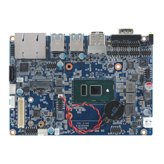
Page 16: Product Overview
ECM-KBLU User’s Manual 2.1 Product Overview 16 ECM-KBLU User’s Manual... -
Page 17: Jumper And Connector List
LCD inverter connector Matching Connector: JST PHR-5 CPU fan connector 4 x 1 wafer, pitch 2.54mm CPU_FAN1 System fan connector 4 x 1 wafer, pitch 2.54mm SYS_FAN1 COM1 Serial Port 1 connector D-sub 9 pin, male ECM-KBLU User’s Manual 17... - Page 18 EC Debug connector 3 x 1 header, pitch 2.00mm SATA_PWR1 SATA Power connector 2 x 1 wafer, pitch 2.00mm Serial ATA connector SATA1 HDMI connector HDMI1 DDR4 SODIMM socket SO_DIMM1 MINI_PCIE1 Mini-PCIe_connector USIM1 SIM card slot 18 ECM-KBLU User’s Manual...
-
Page 19: Setting Jumpers & Connectors
User’s Manual 2.3 Setting Jumpers & Connectors 2.3.1 Serial port 1 pin9 signal select (JRI1) Ring* +12V * Default 2.3.2 Clear CMOS (JBAT1) Normal* Clear CMOS * Default ECM-KBLU User’s Manual 19... -
Page 20: Lcd Backlight Brightness Adjustment (Jbkl_Sel1)
ECM-KBLU User’s Manual 2.3.3 LCD backlight brightness adjustment (JBKL_SEL1) PWM Mode* DC Mode * Default 2.3.4 AT/ATX Input power select (JAT1) * Default 20 ECM-KBLU User’s Manual... -
Page 21: Lcd Inverter Connector (Jbkl1)
User’s Manual 2.3.5 LCD inverter connector (JBKL1) Signal +12V BKLEN VBRIGHT 2.3.6 CPU fan connector (CPU_FAN1) Signal PWM_FAN0 EC_TACH0 +12V ECM-KBLU User’s Manual 21... -
Page 22: System Fan Connector (Sys_Fan1)
ECM-KBLU User’s Manual 2.3.7 System fan connector (SYS_FAN1) Signal +12V EC_TACH1 PWM_FAN1 2.3.8 Serial port 2/3/4/5/6 connector (JCOM2/3/4/5/6) JCOM2 JCOM5 JCOM3 JCOM6 JCOM4 Signal PIN PIN Signal COM_DCD# COM_RXD COM_TXD COM_DTR# COM_DSR# COM_RTS# COM_CTS# COM_RI# 22 ECM-KBLU User’s Manual... -
Page 23: Serial Port 2 In Rs-422/485 Mode (J422_485)
2.3.9 Serial port 2 in RS-422/485 mode (J422_485) Signal PIN PIN Signal 485-422_TXDN 485-422_TXDP 422_RXDP 422_RXDN 2.3.10 General purpose I/O connector (JDIO1) Signal PIN PIN Signal DIO_GP20 DIO_GP10 DIO_GP21 DIO_GP11 DIO_GP22 DIO_GP12 DIO_GP23 DIO_GP13 SMB_SCL_S0 SMB_SDA_S0 ECM-KBLU User’s Manual 23... -
Page 24: Sata Power Connector (Sata_Pwr1)
ECM-KBLU User’s Manual 2.3.11 SATA Power connector (SATA_PWR1) Signal 2.3.12 Power connector (PWR1) Signal Signal +26V +26V 24 ECM-KBLU User’s Manual... -
Page 25: Lvds Connector (Jlvds1)
10 LVDS_DATA0_P LVDS_DATA1_N 11 12 LVDS_DATA0_N LVDS_DATA3_P 15 16 LVDS_DATA2_P LVDS_DATA3_N 17 18 LVDS_DATA2_N LVDS_DATA5_P 21 22 LVDS_DATA4_P LVDS_DATA5_N 23 24 LVDS_DATA4_N LVDS_DATA7_P 27 28 LVDS_DATA6_P LVDS_DATA7_N 29 30 LVDS_DATA6_N LVDS_CLK2_P LVDS_CLK1_P LVDS_CLK2_N LVDS_CLK1_N +12V +12V ECM-KBLU User’s Manual 25... -
Page 26: Usb2.0 Connector (Jusb56)
ECM-KBLU User’s Manual 2.3.14 USB2.0 connector (JUSB56) Signal PIN PIN Signal +5VSB USB_R_DN5 USB_R_DP5 USB_R_DP6 USB_R_DN6 +5VSB 2.3.15 SPI connector (JSPI1) Signal PIN PIN Signal +3.3VSB SPI_CS0# SPI_CLK SPI_MISO SPI_MOSI BIOS_HOLD# BIOS_WP# 26 ECM-KBLU User’s Manual... -
Page 27: Ec Debug Connector (Jec_Rom1)
User’s Manual 2.3.16 EC Debug connector (JEC_ROM1) Signal EC_SMDAT_DEBUG EC_SMCLK_DEBUG 2.3.17 Battery connector (BAT1) Signal +RTCBAT ECM-KBLU User’s Manual 27... -
Page 28: Lpc Connector (Jlpc1)
ECM-KBLU User’s Manual 2.3.18 LPC connector (JLPC1) Signal PIN PIN Signal LPC_AD0 +3.3V LPC_AD1 RST_TPM# LPC_AD2 LPC_LFRAME# LPC_AD3 CLK2_LPC_DEBUG LPC_SERIRQ 2.3.19 Front Panel connector (JFP1) Signal PIN PIN Signal PWRBTN_TO_EC# PM_SYSRST# FP_PWR_LED+ PWR_LED# HDD_LED# CASE_OPEN# 28 ECM-KBLU User’s Manual... -
Page 29: Pc Buzzer Connector (Jbz1)
HD_AGND HD_AGND LINE1-R-IN LINE1-L-IN MIC1-R-IN MIC1-L-IN FRONT-JD LINE1-JD MIC1-JD HD_AGND 2.3.21.1 Signal Description – Audio connector (JAUDIO1) Signal Signal Description LINE1-JD AUDIO IN (LINE_RIN/LIN)sense pin FRONT-JD AUDIO Out(ROUT/LOUT) sense pin MIC1-JD MIC IN (MIC_RIN/LIN) sense pin ECM-KBLU User’s Manual 29... -
Page 30: Aux-032 User's Guide
2.54mm USB connector 5 x 2 header, pitch 2.54mm 2.0mm USB connector 5 x 2 header, pitch 2.0mm 2.0mm USB connector 5 x 2 header, pitch 2.0mm TV / Audio connector 8 x 2 header, pitch 2.54mm 30 ECM-KBLU User’s Manual... -
Page 31: Setting Jumper And Connector
Mic Bais Line out L Line out R SPK L SPK R Line in L Line in R TVGND TVGND COMP 2.0mm USB Connector (JP4) 2.0mm USB Connector (JP5) Signal PIN PIN Signal Signal PIN PIN Signal ECM-KBLU User’s Manual 31... -
Page 32: Bios Setup
ECM-KBLU User’s Manual 3.BIOS Setup 32 ECM-KBLU User’s Manual... -
Page 33: Introduction
If the message disappears before you respond and you still wish to enter Setup, restart the system to try again by turning it OFF then ON or pressing the "RESET" button on the system case. You may also restart by simultaneously pressing <Ctrl>, <Alt>, and <Delete> keys. ECM-KBLU User’s Manual 33... -
Page 34: Using Setup
Note: Some of the navigation keys differ from one screen to another. To Display a Sub Menu Use the arrow keys to move the cursor to the sub menu you want. Then press <Enter>. A “” pointer marks all sub menus. 34 ECM-KBLU User’s Manual... -
Page 35: Getting Help
BIOS Vendor and your systems manufacturer to provide the absolute maximum performance and reliability. Even a seemingly small change to the chipset setup has the potential for causing you to use the override. ECM-KBLU User’s Manual 35... -
Page 36: Bios Setup
<Enter> to accept and enter the sub-menu. 3.6.1 Main Menu This section allows you to record some basic hardware configurations in your computer and set the system clock. 36 ECM-KBLU User’s Manual... -
Page 37: System Language
Visit the Avalue website (www.avalue.com.tw) to download the latest product and BIOS information. 3.6.2 Advanced Menu This section allows you to configure your CPU and other system devices for basic operation through the following sub-menus. ECM-KBLU User’s Manual 37... -
Page 38: Cpu Configuration
Number of cores to enable in each processor Active Processor Cores package. Enabled for Windows XP and Linux (OS optimized Disabled for Hyper-Threading Technology) and Disabled for Hyper-Threading Enabled[Default] other OS (OS not optimized for Hyper-Threading Technology). 38 ECM-KBLU User’s Manual... -
Page 39: Power & Performance
Allows more than two frequency ranges to be Intel® SpeedStep™ Disabled supported. Enable/Disable processor Turbo Mode (requires Enabled[Default], Turbo Mode EMTTM enabled too). AUTO means enabled, unless Disabled max turbo ratio is bigger than 16 – SKL A0 W/A. ECM-KBLU User’s Manual 39... - Page 40 Processors. This 1-Core Ratio Limit Must be greater than or equal to 2-Core ratio Limit, 3-Core Ratio Limit, 4-Core Ratio Limit. 2-Core Ratio Limit with range 0 to 83. The 2-Core Ratio Limit Override 0-83 Minimum range may vary between 40 ECM-KBLU User’s Manual...
-
Page 41: Gt - Power Management Control
Otherwise, leave enabled. 3.6.2.2.2 GT – Power Management Control Item Option Description Enabled[Default], Check to enable render RC6(Render Standby) Disabled standby support. Default Max Frequency[Default] 100Mhz/150Mhz/200Mhz/250Mhz/300Mhz /350Mhz/400Mhz/450Mhz/500Mhz/550Mhz Maximum GT frequency Auto Updated. /600Mhz/650Mhz/700Mhz/750Mhz/800Mhz /850Mhz/900Mhz/950Mhz/1000Mhz/1050Mhz /1100Mhz/1150Mhz/1200Mhz ECM-KBLU User’s Manual 41... -
Page 42: Pch-Fw Configuration
ECM-KBLU User’s Manual 3.6.2.3 PCH-FW Configuration Item Options Description Disabled, When Disabled ME will not be unconfigured on ME Unconfig on RTC Clear Enabled[Default] RTC Clear. 3.6.2.3.1 Firmware Update Configuration 42 ECM-KBLU User’s Manual... -
Page 43: Ptt Configuration
Selects TPM device: PTT or dTPM. PTT – Enables PTT in SkuMgr dTPM 1.2 – Disables dTPM, TPM Device Selection PTT[Default] PTT in SkuMgr Warning! PTT/dTPM will be disabled and all data saved on it will be lost. ECM-KBLU User’s Manual 43... -
Page 44: Trusted Computing
3.6.2.4 Trusted Computing Item Options Description Enables or Disables BIOS support for security device. Disable, Security Device Support O.S. will not show Security Device. TCG EFI protocol Enable[Default] and INT1A interface will not be available. 3.6.2.5 APCI Settings 44 ECM-KBLU User’s Manual... -
Page 45: It8528 Super Io Configuration
USB Standby Power Setting Enabled[Default], during S3/S4/S5. 3.6.2.6 IT8528 Super IO Configuration You can use this item to set up or change the IT8528 Super IO configuration for serial ports. Please refer to 3.6.2.6.1~ 3.6.2.6.6 for more information. ECM-KBLU User’s Manual 45... -
Page 46: Serial Port 1 Configuration
Set Parameters of Serial Port 5 (COME). Serial Port 6 Configuration Set Parameters of Serial Port 6 (COMF). 3.6.2.6.1 Serial Port 1 Configuration Item Option Description Enabled[Default], Serial Port Enable or Disable Serial Port (COM). Disabled 46 ECM-KBLU User’s Manual... -
Page 47: Serial Port 2 Configuration
3.6.2.6.2 Serial Port 2 Configuration Item Option Description Enabled[Default], Serial Port Enable or Disable Serial Port (COM). Disabled UART 232[Default] UART 232 422 485 UART 422 Change the Serial Port as RS232/422/485. UART 485 3.6.2.6.3 Serial Port 3 Configuration ECM-KBLU User’s Manual 47... -
Page 48: Serial Port 4 Configuration
3.6.2.6.4 Serial Port 4 Configuration Item Option Description Enabled[Default], Serial Port Enable or Disable Serial Port (COM). Disabled 3.6.2.6.5 Serial Port 5 Configuration Item Option Description Enabled[Default], Serial Port Enable or Disable Serial Port (COM). Disabled 48 ECM-KBLU User’s Manual... -
Page 49: Serial Port 6 Configuration
User’s Manual 3.6.2.6.6 Serial Port 6 Configuration Item Option Description Enabled[Default], Serial Port Enable or Disable Serial Port (COM). Disabled 3.6.2.7 HW Monitor Item Options Description Enabled, Smart Fan Function Enables or Disables Smart Fan. Disabled[Default] ECM-KBLU User’s Manual 49... -
Page 50: S5 Rtc Wake Settings
Disabled[Default], Fixed Time, system will wake on the hr::min::sec specified. Wake system from S5 Fixed Time Select Dynamic Time, System will wake on the current time Dynamic Time + Increase minute(s). 3.6.2.9 Serial Port Console Redirection 50 ECM-KBLU User’s Manual... -
Page 51: Legacy Console Redirection Settings
Console Redirection Enable or Disable. Enabled 3.6.2.9.1 Legacy Console Redirection Settings Item Option Description Select a COM port to display redirection of Legacy Serial Redirection Port COM1[Default] Legacy OS and Legacy OPROM Messages. 3.6.2.10 Intel TXT Configuration ECM-KBLU User’s Manual 51... -
Page 52: Network Stack Configuration
ECM-KBLU User’s Manual 3.6.2.11 Network Stack Configuration Item Options Description Enabled Network Stack Enable/Disable UEFI Network Stack. Disabled[Default] 3.6.2.12 CSM Configuration 52 ECM-KBLU User’s Manual... -
Page 53: Nvme Configuration
User’s Manual Item Options Description Enabled CSM Support Enable/Disable CSM Support. Disabled[Default] 3.6.2.13 NVMe Configuration 3.6.2.14 USB Configuration The USB Configuration menu helps read USB information and configures USB settings. ECM-KBLU User’s Manual 53... - Page 54 Mass storage device emulation type. ‘AUTO’ Auto[Default] Floppy enumerates devices according to their media Mass Storage Devices Forced FDD format. Optical drives are emulated as ‘CDROM’, drives with no media will be Hard Disk CD-ROM emulated according to a drive type. 54 ECM-KBLU User’s Manual...
-
Page 55: Chipset
User’s Manual 3.6.3 Chipset 3.6.3.1 System Agent (SA) Configuration Item Option Description Enabled[Default] VT-d VT-d capability. Disabled ECM-KBLU User’s Manual 55... -
Page 56: Graphics Configuration
1920x1200 24/2 Port1-EDP to LVDS (Chrotel 7511) Panel EDID Ch7511 EDID Panel Option 1920x1080 18/2 Option. 1280x1024 24/2 1440x900 18/2 1600x1200 24/2 1366x768 24/1 1920x1080 24/2 1680x1050 24/2 LVDS Back Light PWM Select back light PWM duty. 56 ECM-KBLU User’s Manual... -
Page 57: Pch-Io Configuration
User’s Manual 100%[Default] 200[Default] LVDS Back Light PWM Select LVDS back light PWM Frequency. Frequency 3.6.3.2 PCH-IO Configuration Item Option Description Disabled PCH LAN(i219) Controller Enable/Disable onboard NIC. Enabled[Default] ECM-KBLU User’s Manual 57... -
Page 58: Pci Express Configuration
3.6.3.2.1.1 PCI Express Root Port 5(i210/i211) Item Option Description Enabled[Default], PCI Express Root Port 5 Control the PCI Express Root Port. Disabled Unknown Identify the SATA Topology if it is Default or Topology x1[Default] ISATA or Flex or DirectConnect or M2. 58 ECM-KBLU User’s Manual... - Page 59 Identify the SATA Topology if it is Default or Topology ISATA or Flex or DirectConnect or M2. Sata Express Set the ASPM Level: Force L0s – Force all Disabled[Default], links to L0s State AUTO – BIOS auto ASPM configure DISABLE – Disables ASPM. ECM-KBLU User’s Manual 59...
- Page 60 Set the ASPM Level: Force L0s – Force all links to L0s State AUTO – BIOS auto ASPM configure DISABLE – Disables ASPM. L0sL1 Auto Disabled[Default], L1.1 L1 Substates PCI Express L1 Substates settings. L1.2 L1.1 & L1.2 60 ECM-KBLU User’s Manual...
- Page 61 L0s State AUTO – BIOS auto ASPM configure DISABLE – Disables ASPM. L0sL1 Auto Disabled[Default], L1.1 L1 Substates PCI Express L1 Substates settings. L1.2 L1.1 & L1.2 Auto[Default] Gen1 PCIe Speed Configure PCIe Speed. Gen2 Gen3 ECM-KBLU User’s Manual 61...
-
Page 62: Sata And Rst Configuration
ISATA or Flex or DirectConnect or M2. Flex Enabled[Default] Port 1 Enable or Disable SATA Port. Disabled Hard Disk Drive[Default] Identify the SATA port is connected to Solid SATA Device Type Solid State Drive State Drive or Hard Disk Drive. 62 ECM-KBLU User’s Manual... -
Page 63: Usb Configuration
ISATA or Flex or DirectConnect or M2. Flex 3.6.3.2.3 USB Configuration Item Option Description Option to disable Compliance Mode. Default FALSE[Default], XHCI Disable Compliance Mode is FALSE to not disable Compliance Mode. TRUE Set TRUE to disable Compliance Mode. ECM-KBLU User’s Manual 63... -
Page 64: Hd Audio Configuration
Control Detection of the HD-Audio device. Disable = HDA Disabled will be unconditionally disabled Enabled = HDA will be HD Audio Enabled unconditionally enabled Auto = HDA will be enabled if Auto[Default], present, disabled otherwise. 3.6.4 Security 64 ECM-KBLU User’s Manual... -
Page 65: Secure Boot
Disabled[Default] Attempt Secure Boot User mode with enrolled Platform Key(PK) 2.CSM Enabled function is disabled. Secure Boot mode selector: Standard/Custom. In Standard Secure Boot Mode Custom mode Secure Boot Variables can be Custom[Default] configured without authentication. ECM-KBLU User’s Manual 65... -
Page 66: Key Management
Allow to provision factory default Secure Provision Factory Defaults Enabled Boot keys when System is in Setup Mode. 3.6.5 Boot Item Option Description Number of seconds to wait for setup activation Setup Prompt Timeout 1~ 65535 66 ECM-KBLU User’s Manual... -
Page 67: Save And Exit
Enables or disables boot with initialization of a Disabled[Default] Fast Boot minimal set of devices required to launch active Enabled boot option. Has no effect for BBS boot options. Boot Option #1 Set the system boot order. 3.6.6 Save and exit ECM-KBLU User’s Manual 67... -
Page 68: Save Changes And Reset
This option restores all BIOS settings to the factory default. This option is useful if the controller exhibits unpredictable behavior due to an incorrect or inappropriate BIOS setting. 3.6.6.4 Launch EFI Shell from filesystem device Attempts to Launch EFI Shell application (Shellx64.efi) from one of the available filesystem devices. 68 ECM-KBLU User’s Manual... -
Page 69: Drivers Installation
User’s Manual 4. Drivers Installation Note: Installation procedures and screen shots in this section are for your reference and may not be exactly the same as shown on your screen. ECM-KBLU User’s Manual 69... -
Page 70: Install Chipset Driver
Windows 10 operation system. If the warning message appears while the installation process, click Continue to go on. Step 3. Click Install. Step1. Click Next. Step 4. Setup completed. Step 2. Click Accept. 70 ECM-KBLU User’s Manual... -
Page 71: Install Me Driver
If the warning message appears while the installation process, click Continue to go on. Step 3. Click Next to continue installation. Step 4. Click Finish to complete setup. Step1. Click Next to start installation. Step 2. Click Next. ECM-KBLU User’s Manual 71... -
Page 72: Install Vga Driver
Windows 10 operation system. Step 3. Click Next. Step 1. Click Next to continue installation. Step 4. Click Next. Step 2. Click Yes to accept license agreement. Step 5. Click Finish to complete setup. 72 ECM-KBLU User’s Manual... -
Page 73: Install Audio Driver (For Realtek Alc892)
All drivers can be found on the Avalue Official Website: http://www.avalue.com.tw. Note: The installation procedures and screen shots in this section are based on Windows 10 operation system. Step 1. Click Next to continue setup. Step 2. Click Finish to complete the setup. ECM-KBLU User’s Manual 73... -
Page 74: Install Ethernet Driver
Windows 10 operation system. Step 3. Click Next. Step 1. Click Next to continue installation. Step 4. Click Install. Step 2. Click Next. Step 5. Click Finish to complete setup. 74 ECM-KBLU User’s Manual... -
Page 75: Install Serial Io Driver
Windows 10 operation system. Step 3. Click Next. Step 1. Click Next to continue installation. Step 4. Click Next. Step 2. Click Next. Step 5. Click Finish to complete setup. ECM-KBLU User’s Manual 75... -
Page 76: Install Irst Driver
Note: The installation procedures and screen shots in this section are based on Windows 10 operation system. Step 3. Click Next. Step 1. Click Next to continue installation. Step 4. Click Next. Step 5. Click Next. Step 2. Click Next. 76 ECM-KBLU User’s Manual... - Page 77 User’s Manual Step 6. Click Finish to complete setup. ECM-KBLU User’s Manual 77...
-
Page 78: Mechanical Drawing
ECM-KBLU User’s Manual 5. Mechanical Drawing 78 ECM-KBLU User’s Manual... - Page 79 User’s Manual Unit: mm ECM-KBLU User’s Manual 79...
Need help?
Do you have a question about the ECM-KBLU and is the answer not in the manual?
Questions and answers