
Related Manuals for Quectel LG69T AA


Summary of Contents for Quectel LG69T AA
- Page 1 LG69T (AA,AD) EVB User Guide GNSS Module Series Version: 1.0 Date: 2022-06-20 Status: Released...
- Page 2 GNSS Module Series At Quectel, our aim is to provide timely and comprehensive services to our customers. If you require any assistance, please contact our headquarters: Quectel Wireless Solutions Co., Ltd. Building 5, Shanghai Business Park Phase III (Area B), No.1016 Tianlin Road, Minhang District, Shanghai...
- Page 3 Except as otherwise set forth herein, nothing in this document shall be construed as conferring any rights to use any trademark, trade name or name, abbreviation, or counterfeit product thereof owned by Quectel or any third party in advertising, publicity, or other aspects.
-
Page 4: Safety Information
The following safety precautions must be observed during all phases of operation, such as usage, service or repair of any terminal incorporating Quectel GNSS module. Manufacturers of the terminal should send the following safety information to users and operating personnel, and incorporate these guidelines into all manuals supplied with the product. -
Page 5: About The Document
GNSS Module Series About the Document Document Information Title LG69T (AA,AD) EVB User Guide Subtitle GNSS Module Series Document Type EVB User Guide Document Status Released Revision History Version Date Description 2020-04-23 Creation of the document 2022-06-20 First official release LG69T(AA,AD)_EVB_User_Guide 4 / 31... -
Page 6: Table Of Contents
GNSS Module Series Contents Safety Information ............................3 About the Document ..........................4 Contents ..............................5 Table Index ..............................6 Figure Index ..............................7 Introduction ............................8 Special Mark ..........................8 1.1. General Overview ..........................9 EVB Kit ............................9 2.1. - Page 7 GNSS Module Series Table Index Table 1: Special Mark ........................... 8 Table 2: List of Kit Components ........................9 Table 3: Detailed EVB Interfaces ....................... 12 Table 4: J501 Pin Detailed Description ...................... 13 Table 5: J302 Pin Detailed Description ...................... 14 Table 6: QGNSS Interface Explanation......................
- Page 8 GNSS Module Series Figure Index Figure 1: EVB Kit Accessories ........................9 Figure 2: EVB and Components Assembly ....................10 Figure 3: EVB Top View ..........................11 Figure 4: IMU Axis Direction ........................15 Figure 5: Installation Diagram ........................16 Figure 6: LG69T (AA) Calibration Status ....................18 Figure 7: USB Ports ...........................
-
Page 9: Introduction
GNSS Module Series Introduction This document provides information on the steps needed to evaluate the Quectel LG69T (AA) and LG69T (AD) using the Evaluation Board (EVB). The EVB is a reference tool that allows you to become familiar with the LG69T (AA) and LG69T (AD). -
Page 10: General Overview
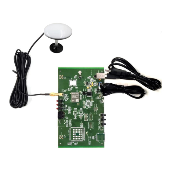
General Overview 2.1. EVB Kit The EVB Kit includes: Evaluation Board (EVB), Quectel Active GNSS Antenna, Micro-USB Cable, Type-B USB Cable, Bolts and Coupling Nuts. Download the software tools (QCOM, QGNSS and GNSSFlashTool) from our website Download Zone or request them from Quectel Technical Support. -
Page 11: Connect Cables And Antenna To Evb
GNSS Module Series Type-B USB Cable Quectel Active GNSS antenna: YEGM011BA GNSS Antenna Request the Antenna Datasheet from Quectel Technical Support. Sheet providing instructions on how to connect the EVB Instruction Sheet and its components, detailed information on EVB contents, etc. -
Page 12: Evb User Interfaces
GNSS Module Series EVB User Interfaces 3.1. EVB Top View EVB top view is shown in the figure below. D309 D310 TXD/1PPS GEO_F indication LED indication LED J401 LG69T_ANT J501 D109 5V/3.3V indication LED (Supported by LG69T (AA)) U301 GNSS module J302 EVB version Test points... -
Page 13: Board User Interfaces
GNSS Module Series 3.2. Board User Interfaces The EVB interfaces are detailed in the table below. Table 3: Detailed EVB Interfaces Function Interfaces Description Power supply input: J101 ⚫ Power Supply DC power supply: 4.5–5.5 V, typ. 5.0 V. POWER_5V ⚫... - Page 14 GNSS Module Series J302 Pins are detailed in Table 5 below. Test Points Test points distributions are shown below: J501 Pin Assignment: WHEELTICK Table 4: J501 Pin Detailed Description Pin Name Description WHEELTICK Odometer wheel-tick input. Forward/Backward signal input. Low level: Forward. Ground J302 Pin Assignment: SPI_MOSI...
- Page 15 GNSS Module Series Table 5: J302 Pin Detailed Description Pin Name Description SPI_MOSI NC (Not connected) SPI_SCK TXD1 TXD1 Transmit data RXD1 RXD1 Receive data 1PPS One pulse per second SPI_CS SPI_MISO TXD2 TXD2 Transmit data RXD2 RXD2 Receive data Ground LG69T(AA,AD)_EVB_User_Guide 14 / 31...
-
Page 16: Dr Application
GNSS Module Series DR Application LG69T (AA) supports Dead Reckoning (DR) function. This chapter outlines how to configure the DR function. A valid module calibration is essential for utilizing its DR capabilities, see Chapter 4.2 for details. Fix the module on the vehicle frame. Any displacement, turn or tilt of the device, however small, will cause performance issues and/or void calibration. -
Page 17: Calibration Procedure
GNSS Module Series The car wheeltick access port RF input Wheeltick input EVB must be fixed on the car frame Power supply and get data Figure 5: Installation Diagram 4.2. Calibration Procedure This chapter details the calibration steps of LG69T (AA) EVB. Before calibration, it is necessary to confirm the EVB installation angle. -
Page 18: Evb Installation Angle Confirmation
GNSS Module Series 4.2.1. EVB Installation Angle Confirmation Before the 6-axis accelerometer sensor is available, the EVB installation angle needs to be confirmed by following steps: Step 1: Install the EVB on a vehicle and connect the antenna. Step 2: Start the vehicle and power on the EVB. Step 3: Keep the vehicle stationary for at least 20 s on a flat road (the tolerance of the gravity direction is 1°–2°). -
Page 19: Calibration Result Monitoring
GNSS Module Series NOTE Please note that the hybrid GNSS/DR navigation mode will not be available until a proper calibration procedure is performed, and that only single GNSS navigation will be available. 4.3. Calibration Result Monitoring The calibration result will be reported in an NMEA message. The following figure illustrates how to check the calibration status message. -
Page 20: Communication Via Qcom Tool
Step 3: View the USB port numbers in the Device Manager. Figure 7: USB Ports Step 4 : Install the QCOM tool provided by Quectel. The COM interface for QCOM port setting i s shown in the figure below (the LG69T (AA) module supports 460800 bps... - Page 21 GNSS Module Series Step 5: Select the correct “COM Port” (shown in Figure 7 above) and the “Baudrate”. Step 6: Click “Open Port” to establish communication with the EVB. The NMEA message output by the module will be displayed in the receiving bar of the QCOM tool. Figure 9: NMEA Sentence Output –...
-
Page 22: Test Via Qgnss Tool
Test via QGNSS Tool This chapter explains how to use the QGNSS software tool for verifying the status of GNSS modules. You can request the QGNSS from Quectel Technical Support. For more information on QGNSS use, see document [3]. 6.1. QGNSS Setting Step 1: Assemble the EVB components. - Page 23 GNSS Module Series Step 4: Click the “Connect or disconnect” button. Depending on the module version, the interface shown below appears once the module is connected. Figure 11: QGNSS Interface (Connected) – LG69T (AA) Figure 12: QGNSS Interface (Connected) – LG69T (AD) LG69T(AA,AD)_EVB_User_Guide 22 / 31...
-
Page 24: Qgnss Interface Explanation
GNSS Module Series 6.1.1. QGNSS Interface Explanation You can view GNSS information, such as C/N message, time, position, speed, and precision in the QGNSS interface. See the following table to find out more about these parameters. Table 6: QGNSS Interface Explanation Icon Explanation This sky view interface shows the position of the satellites in use. - Page 25 GNSS Module Series ⚫ Longitude (unit: degree) ⚫ Latitude (unit: degree) Altitude (MSL) (unit: m) ⚫ ⚫ Altitude (EPH) (unit: m) ⚫ Receiver speed (unit: km/h) Horizontal dilution of precision ⚫ ⚫ Position dilution of precision ⚫ Fix Mode: 2D, 3D Quality Indicator: GPS SPS mode ⚫...
-
Page 26: Firmware Download And Upgrade Via Gnssflashtool
Firmware Download and Upgrade via GNSSFlashTool The modules upgrade firmware with GNSSFlashTool via the UART interface. You can request the GNSSFlashTool from Quectel Technical Support. For more information about GNSSFlashTool use, see document [4]. 7.1. Firmware Download in Boot Download Mode Before you start the module firmware download process: First: Connect the EVB to a PC with a Micro-USB cable. - Page 27 GNSS Module Series Step 2: Select “LG69TAA_Download” for the modules as shown in the figure below. Figure 14: Firmware Download – Step 2 Step 3: Click “Open File” select module firmware, e.g. “LG69TAANR01A01V01_4WDR_ST_BETA0810A_BOOT.bin” LG69T (AA) module, “LG69TADNR01A01V01_BOOT.bin” for LG69T (AD). Figure 15: Firmware Download –...
-
Page 28: Firmware Upgrade In Normal Operating Mode
GNSS Module Series Step 5: Upon successful firmware download, the GNSSFlashTool green progress bar on the screen will indicate “100%”. Figure 17: Successful Firmware Download – Step 5 7.2. Firmware Upgrade in Normal Operating Mode Before you start the firmware upgrade process, connect the EVB to a PC with a Micro-USB Cable. First: Connect the EVB to a PC with a Micro-USB Cable. - Page 29 GNSS Module Series Step 2: Select “LG69TAA_Upgrade” in the drop-down box of “Tool Options”. Figure 19: Firmware Upgrade – Step 2 Step 3: Click “Open File” select module firmware, e.g. “LG69TAANR01A01V01_4WDR_ST_BETA0810A_UPG.bin” LG69T (AA) “LG69TADNR01A01V01_UPG.bin” for LG69T (AD). Figure 20: Firmware Upgrade – Step 3 Step 4: Confirm the “Port”...
- Page 30 GNSS Module Series Step 5: Upon successful firmware upgrade, the GNSSFlashTool green progress bar on the screen will indicate “PASS”. Figure 22: Successful Firmware Upgrade – Step 5 LG69T(AA,AD)_EVB_User_Guide 29 / 31...
-
Page 31: Appendix Reference
GNSS Module Series Appendix Reference Table 7: Related Document Document Name Quectel_LG69T(AA,AD,AI,AJ)_GNSS_Protocol_Specification Quectel_QCOM_User_Guide Quectel_QGNSS_User_Guide Quectel_GNSSFlashTool_User_Guide Table 8: Terms and Abbreviations Abbreviation Description BeiDou Navigation Satellite System Circular Error Probable Carrier-to-Noise Ratio COM Port Communication Port Digital Input Digital Output Dead Reckoning Electrostatic Discharge Evaluation Board Galileo... - Page 32 GNSS Module Series Input/Output Light Emitting Diode Master In Slave Out MISO Master Out Slave In MOSI Mean Sea Level NMEA National Marine Electronics Association Personal Computer Printed Circuit Board 1PPS One Pulse Per Second Pseudorandom Noise QZSS Quasi-Zenith Satellite System Radio Technical Commission for Maritime services RTCM Real-Time Kinematic...
Need help?
Do you have a question about the LG69T AA and is the answer not in the manual?
Questions and answers