
Related Manuals for Quectel LG69T AM


Summary of Contents for Quectel LG69T AM
- Page 1 LG69T (AM,AS) EVB User Guide GNSS Module Series Version: 1.0 Date: 2022-10-20 Status: Released...
- Page 2 GNSS Module Series At Quectel, our aim is to provide timely and comprehensive services to our customers. If you require any assistance, please contact our headquarters: Quectel Wireless Solutions Co., Ltd. Building 5, Shanghai Business Park Phase III (Area B), No.1016 Tianlin Road, Minhang District, Shanghai...
- Page 3 Except as otherwise set forth herein, nothing in this document shall be construed as conferring any rights to use any trademark, trade name or name, abbreviation, or counterfeit product thereof owned by Quectel or any third party in advertising, publicity, or other aspects.
-
Page 4: Safety Information
Quectel LG69T(AM) module. Manufacturers of the terminal should send the following safety information to users and operating personnel, and incorporate these guidelines into all manuals supplied with the product. Otherwise, Quectel assumes no liability for customers’ failure to comply with these precautions. -
Page 5: About The Document
GNSS Module Series About the Document Document Information Title LG69T (AM,AS) EVB User Guide Subtitle GNSS Module Series Document Type EVB User Guide Document Status Released Revision History Version Date Description 2022-03-14 Creation of the document 2022-10-20 First official release LG69T(AM,AS)_EVB_User_Guide 4 / 45... -
Page 6: Table Of Contents
GNSS Module Series Contents Safety Information ............................3 About the Document ..........................4 Contents ..............................5 Table Index ..............................6 Figure Index ..............................7 Introduction ............................8 General Overview ..........................9 2.1. EVB Kit ............................9 2.2. Connect Cables and Antenna to EVB ..................10 EVB Interfaces ........................... - Page 7 GNSS Module Series Table Index Table 1: List of Kit Components ......................... 10 Table 2: Detailed EVB Interfaces ....................... 13 Table 3: J302 Pin Assignment ........................14 Table 4: J302 Pin Detailed Description ...................... 15 Table 5: QGNSS Interface Explanation...................... 20 Table 6: NTRIP Caster Server Options ......................
- Page 8 GNSS Module Series Figure Index Figure 1: EVB and Components ........................9 Figure 2: EVB and Components Assembly ....................11 Figure 3: EVB Top View ..........................12 Figure 4: USB Ports ........................... 16 Figure 5: QCOM Interface for COM Port Setting ..................16 Figure 6: RTCM Message Output of LG69T (AS) –...
-
Page 9: Introduction
GNSS Module Series Introduction This document provides information on the steps needed to evaluate the Quectel LG69T (AM) and LG69T (AS) GNSS modules using the Evaluation Board (EVB). The EVB is a convenient tool that allows you to become familiar with the modules. -
Page 10: General Overview
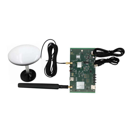
GNSS Module Series General Overview 2.1. EVB Kit The EVB kit includes: Evaluation Board (EVB), Quectel Active GNSS Antenna, LTE Antenna, Micro-USB Cable, Type-B USB Cable, Bolts and Coupling Nuts. The EVB kit components are shown in the figure below. Check... -
Page 11: Connect Cables And Antenna To Evb
4 pairs ⚫ NOTE Request Quectel Technical Support (support@quectel.com) for details about Quectel Active GNSS Antenna and LTE Antenna. 2.2. Connect Cables and Antenna to EVB The connection between the EVB and its components is shown in the figure below. For more information on how to connect the EVB and its components, see the instruction sheet inside the EVB Kit. - Page 12 GNSS Module Series Figure 2: EVB and Components Assembly ⚫ NOTE Make sure that the active GNSS antenna is placed with a clear line of sight to the sky. LG69T(AM,AS)_EVB_User_Guide 11 / 45...
-
Page 13: Evb Interfaces
GNSS Module Series EVB Interfaces 3.1. EVB Top View EVB top view is shown in the figure below. D309 TXD/1PPS D310 indication LED J603 GEO_F/RTK_S LTE-ANT indication LED D109 5 V/3.3 V indication LED J401 LG69T GNSS_ANT U301 U601 LG69T GNSS module EG25-G module J302 EVB Version... -
Page 14: Evb Interfaces
GNSS Module Series 3.2. EVB Interfaces The EVB interfaces are detailed in the table below. Table 2: Detailed EVB Interfaces Function Interfaces Description J201 Power supply input: USB_UART ⚫ Power Supply DC power supply: 4.5–5.5 V, typ. 5.0 V J601 ⚫... - Page 15 GNSS Module Series Function Interfaces Description S101 Powers the EVB on/off. Power Switch S201 Short press the button to reset the GNSS RESET_GNSS module. Switches S601 Short press the button to reset the EG25-G Buttons RESET_EC20 module. Press and hold the BOOT_GNSS button first and then flip the power switch to ON position S202 to set the GNSS module to Boot download...
- Page 16 GNSS Module Series Table 4: J302 Pin Detailed Description Pin Name Description NC (Not connected) SPI_MOSI SPI_SCK TXD1 transmits data TXD1 RXD1 receives data RXD1 One pulse per second 1PPS SPI_CS SPI_MISO TXD2 TXD2 transmits data RXD2 RXD2 receives data Ground LG69T(AM,AS)_EVB_User_Guide 15 / 45...
-
Page 17: Communication Via Qcom Tool
Step 2: View the USB port numbers in the PC OS system Device Manager. Figure 4: USB Ports Step 3: Install the QCOM tool provided by Quectel. The QCOM interface for COM port setting is shown in the figure below (default baud rate: 460800 bps Figure 5: QCOM Interface for COM Port Setting Step 4: Select the correct “COM Port”... - Page 18 GNSS Module Series Figure 6: RTCM Message Output of LG69T (AS) – Displayed on QCOM Tool Interface Figure 7: NMEA Message Output of LG69T (AM) – Displayed on QCOM Tool Interface LG69T(AM,AS)_EVB_User_Guide 17 / 45...
-
Page 19: Gnss Module Firmware Upgrade Via Qgnss Tool
GNSS Module Series GNSS Module Firmware Upgrade via QGNSS Tool This chapter explains how to use the QGNSS software tool for verifying the status of GNSS modules and firmware upgrading. For more information about QGNSS usage, see document [2] QGNSS User Guide. - Page 20 GNSS Module Series Figure 9: QGNSS Interface (Connected) Step 5: Click “Deviation Map” button in the QGNSS toolbar, select “Setup” interface to convert WGS84 (World Geodetic System) to ECEF (Geocentric Coordinate System). Enter the corresponding coordinates of Lon (Degree), Lat (Degree), Alt (m) in the LLA column, and then select “Calculate CEP50”...
-
Page 21: Qgnss Interface Explanation
GNSS Module Series Figure 11: Converting WGS84 to ECEF ⚫ NOTE WGS84 can be converted to ECEF regardless of whether QGNSS is connected or unconnected . 5.2. QGNSS Interface Explanation You can view GNSS information, such as C/N message, time, position, speed, and precision in the QGNSS interface. - Page 22 GNSS Module Series Icon Explanation GPS satellite BDS satellite GLONASS satellite Galileo satellite QZSS satellite NavIC (IRNSS) satellite ⚫ PRN 30 C/N is 39 dB-Hz. ⚫ Column in bright red means that the navigation data of the satellites are in use. ⚫...
-
Page 23: Firmware Upgrade
GNSS Module Series 5.3. Firmware Upgrade The firmware of GNSS module’s MCU is upgraded with QGNSS via the UART interface. 5.3.1. Module’s MCU Firmware Download in Boot Download Mode Before the module’s MCU firmware download process, connect the EVB to a PC with a Micro-USB cable and flip the power switch (S101) to OFF position. - Page 24 GNSS Module Series Step 3: Select “MCU_Download” and then click button to select firmware file, e.g., “LG69TAMNR01A02V02_RTK_PO_BOOT.bin”. ③ Figure 14: Select MCU Firmware to be Downloaded Step 4: Press and hold the BOOT_GNSS button before flipping the power switch to ON position, and then release the BOOT_GNSS button to set the module to Boot download mode.
-
Page 25: Module's Mcu Firmware Upgrade In Normal Operating Mode
GNSS Module Series Step 5: Upon successful MCU firmware download, the QGNSS tool progress bar on the screen will indicate “100 %”. Figure 16: Successful MCU Firmware Downloading 5.3.2. Module’s MCU Firmware Upgrade in Normal Operating Mode Before the module’s MCU firmware upgrade process, connect the EVB to a PC with a Micro-USB cable and flip the power switch (S101) to OFF position. - Page 26 GNSS Module Series Step 2: Select “Download Baudrate” in the drop-down box of “Settings”. ② Figure 18: Configure Tool for MCU Firmware Upgrading Step 3: Select “MCU_Upgrade” then click select firmware file, e.g., “LG69TAMNR01A02V02_RTK_PO_UPG.bin”. ③ Figure 19: Select MCU Firmware to be Upgraded LG69T(AM,AS)_EVB_User_Guide 25 / 45...
- Page 27 GNSS Module Series Step 4: Click button before flipping the power switch to ON position, and then start downloading the MCU firmware. ④ Figure 20: Start MCU Firmware Upgrading Step 5: Upon successful firmware upgrading, the QGNSS tool progress bar on the screen will indicate “100 %”.
-
Page 28: Gnss Firmware Upgrade
GNSS Module Series 5.3.3. GNSS Firmware Upgrade Before GNSS firmware upgrade process, connect the EVB to a PC with a Micro-USB cable and flip the power switch (S101) to OFF position. To download GNSS firmware in Normal operating mode: Step 1: Open QGNSS tool, and click “Tools” and select “Firmware Download” in the drop-down box. ①... - Page 29 GNSS Module Series ③ Figure 24: Select GNSS Firmware to be Upgraded Step 4: Click button before flipping the power switch to ON position, and then start downloading the firmware. ④ Figure 25: Start GNSS Firmware Upgrading LG69T(AM,AS)_EVB_User_Guide 28 / 45...
- Page 30 GNSS Module Series Step 5: Upon successful firmware upgrading, the QGNSS tool progress bar on the screen will be indicate “100 %”. Figure 26: Successful GNSS Firmware Upgrading ⚫ NOTE Make sure the GNSS module is in Continuous mode before GNSS firmware upgrading. LG69T(AM,AS)_EVB_User_Guide 29 / 45...
-
Page 31: Eg25-G Module Firmware Upgrade Via Qflash Tool
GNSS Module Series EG25-G Module Firmware Upgrade via QFlash Tool This chapter explains how to use the QFlash software tool to upgrade EG25-G module firmware. For more information about QFlash usage, see document [3] QFlash User Guide. To upgrade EG25-G module firmware: Step 1: Before EG25-G module firmware upgrade process, connect the EVB to a PC with a Micro-USB cable via USB_EC20 interface (J601). - Page 32 GNSS Module Series Step 2: Flip the power switch (S101) to ON position to power on the EVB. View the AT and DM COM port number in the Device Manager, as shown in the figure below. Figure 28: USB Ports Step 3: Open QFlash tool, click “Load FW File”...
- Page 33 GNSS Module Series Figure 30: Firmware Downloading Step 5: Upon successful firmware downloade, the QFlash tool progress bar on the screen will indicate “PASS”. Figure 31: Successful Firmware Downloading LG69T(AM,AS)_EVB_User_Guide 32 / 45...
- Page 34 GNSS Module Series ⚫ NOTE The software version and QFlash tool cannot be stored in directories containing Chinese characters, special characters, and spaces when you download the firmware of the EG25-G module. Otherwise, the download will fail. LG69T(AM,AS)_EVB_User_Guide 33 / 45...
-
Page 35: Rtk Application
GNSS Module Series RTK Application RTK is a technique for increasing GNSS positioning accuracy. It involves the use of one stationary reference receiver, called the base station, that sends correction data to one moving receiver, called the rover. The correction data source can either be a: ⚫... -
Page 36: Hardware Connection
GNSS Module Series The connection to the base station with STRSVR tool via NTRIP or TCP protocol illustrates below: GNSS Raw GNSS Raw Measurements Measurements Ntrip/TCP Server LG69T (AS) LG69T(AS) Base Station Base Station STRSVR ① Using NTRIP Protocol ② Using TCP Protocol RTCM RTCM Cellular... -
Page 37: Base Station Configuration
GNSS Module Series GNSS antenna antenna SIM card Micro-USB cables Figure 33: EVB and Components Assembly 7.2. Base Station Configuration 7.2.1. Base Station Receiver Mode Configuration The following command is used to set the Receiver Mode of base station. The base station needs to work in static mode and there are two ways to enter static mode: Survey-in mode and Fixed mode. -
Page 38: Base Station Rtcm Msm Mode Configuration
GNSS Module Series 7.2.2. Base Station RTCM MSM Mode Configuration The following command is used to set the RTCM MSM (Multiple Signal Messages) mode of base station. For more information, see document [4] Protocol Specification. Synopsis: $PQTMSETMSMMODE,<Mode>*<Checksum><CR><LF> 7.3. RTK Data Interaction Mode Configuration RTK data interaction mode is configured by sending the command to the AT port of the EG25-G module. -
Page 39: Strsvr Tool Configuration
GNSS Module Series ⚫ If successful, the module returns: +QGNSSPARAM OK ⚫ If failed, the module returns: +QGNSSPARAM ERR 7.4. STRSVR Tool Configuration The main function of STRSVR tool is to transmit the differential data of the base station to the rover via NTRIP or TCP protocol over the network. - Page 40 GNSS Module Series Figure 35: Configure STRSVR Tool – NTRIP 2 Table 6: NTRIP Caster Server Options Parameter Description NTRIP Caster Host Server IP address Port Server port Mountpoint Mount point User-ID Username Password Password Step 5: For “(1) Output”, set RTK account configuration information in the “NTRIP Caster Server Options”...
-
Page 41: Steps For Data Transmission Via Tcp Protocol
GNSS Module Series Step 6: Click “Start” to start configuring the server. Once the configuration is complete, the STRSVR tool progress bar on the screen will indicate 100%. Figure 37: Configure STRSVR Tool – NTRIP 4 7.4.2. Steps for Data Transmission via TCP Protocol Step 1: Send AT+QGNSSPARAM=1,1,"ip","port"... - Page 42 GNSS Module Series Step 4: For “(0) Input”, set RTK account configuration information in the “TCP Server Options” interface. Figure 39: Configure STRSVR Tool – TCP 2 Table 7: TCP Server Options Parameter Description Server Host Server IP address Port Server port ⚫...
- Page 43 GNSS Module Series Step 6: Click “Start” to start configuring the server. Once the configuration is complete, the STRSVR tool progress bar on the screen will indicate 100%. Figure 41 : Configure STRSVR Tool – TCP 4 LG69T(AM,AS)_EVB_User_Guide 42 / 45...
-
Page 44: Appendix Reference
GNSS Module Series Appendix Reference Table 8: Related Document Document Name Quectel_QCOM_User_Guide [2] Quectel_QGNSS_User_Guide [3] Quectel_QFlash_User_Guide Quectel_LG69T(AS)_GNSS_Protocol_Specification Table 9: Terms and Abbreviations Abbreviation Description 2 Dimension 3 Dimension Attention BeiDou Navigation Satellite System Circular Error Probable Carrier-to-Noise Ratio Digital Input Digital Output Dead Reckoning Ellipsoidal Height... - Page 45 GNSS Module Series Abbreviation Description Galileo Galileo Satellite Navigation System (EU) GLONASS Global Navigation Satellite System (Russia) Ground GNSS Global Navigation Satellite System Global Positioning System Input/Output Light Emitting Diode Micro-USB Micro Universal Serial Bus Master In Slave Out MISO Master Out Slave In MOSI Mean Sea Level...
- Page 46 GNSS Module Series Abbreviation Description Transmission Control Protocol TransFlash Thread Neill-Concelman TTFF Time to First Fix Transmit Data (Pin) Universal Serial Bus Coordinated Universal Time LG69T(AM,AS)_EVB_User_Guide 45 / 45...
Need help?
Do you have a question about the LG69T AM and is the answer not in the manual?
Questions and answers