Quectel GNSS Module Series User Manual
Hide thumbs
Also See for GNSS Module Series:
- User manual (23 pages) ,
- User manual (29 pages) ,
- User manual (18 pages)

Related Manuals for Quectel GNSS Module Series


Summary of Contents for Quectel GNSS Module Series
- Page 1 LG69T (AA,AD) EVB User Guide GNSS Module Series Version: 1.0.0 Date: 2021-09-16 Status: Preliminary...
- Page 2 GNSS Module Series At Quectel, our aim is to provide timely and comprehensive services to our customers. If you require any assistance, please contact our headquarters: Quectel Wireless Solutions Co., Ltd. Building 5, Shanghai Business Park Phase III (Area B), No.1016 Tianlin Road, Minhang District, Shanghai...
- Page 3 Except as otherwise set forth herein, nothing in this document shall be construed as conferring any rights to use any trademark, trade name or name, abbreviation, or counterfeit product thereof owned by Quectel or any third party in advertising, publicity, or other aspects.
-
Page 4: Safety Information
Quectel LG69T(AP) module. Manufacturers of the terminal should send the following safety information to users and operating personnel, and incorporate these guidelines into all manuals supplied with the product. Otherwise, Quectel assumes no liability for customers’ failure to comply with these precautions. -
Page 5: About The Document
GNSS Module Series About the Document Document Information Title LG69T (AA,AD) EVB User Guide Subtitle GNSS Module Series Document Type EVB User Guide Document Status Preliminary Revision History Version Date Description 2020-04-23 Creation of the document 1.0.0 2021-09-16 Preliminary LG69T(AA,AD)_EVB_User_Guide... -
Page 6: Table Of Contents
GNSS Module Series Contents Safety Information ............................3 About the Document ..........................4 Contents ..............................5 Table Index ..............................6 Figure Index ..............................7 Introduction ............................8 General Overview ..........................9 EVB Kit Accessories ........................9 2.1. Connecting Cables and Antenna to EVB ................. 10 2.2. - Page 7 GNSS Module Series Table Index Table 1: List of Accessories .......................... 9 Table 2: Detailed EVB Interfaces ....................... 12 Table 3: J501 Pin Detailed Description ...................... 13 Table 4: J302 Pin Detailed Description ...................... 14 Table 5: QGNSS Interface Explained ......................21 Table 6: Related Document ........................
- Page 8 GNSS Module Series Figure Index Figure 1: EVB Kit Accessories ........................9 Figure 2: EVB and Accessories Assembly ....................10 Figure 3: EVB Side View ..........................11 Figure 4: IMU Axis Direction ........................15 Figure 5: QGNSS Setting ........................... 16 Figure 6: LG69T (AA) Calibration Status ....................18 Figure 7: QGNSS Setting ...........................
-
Page 9: Introduction
GNSS Module Series Introduction This document provides info on the steps needed to evaluate the Quectel LG69T (AA) and LG69T (AD) modules using the Evaluation Board (EVB). The EVB is a reference tool that allows you to become familiar with the LG69T (AA) and LG69T (AD) modules. -
Page 10: General Overview
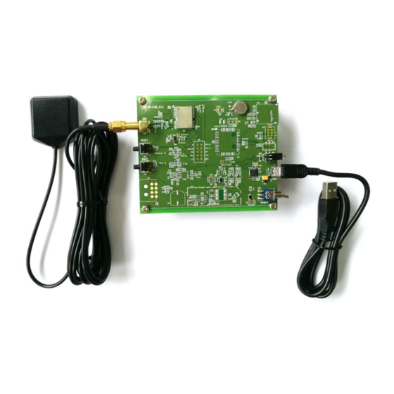
The EVB Kit includes: Evaluation Board (EVB), Active GNSS Antenna, Micro-USB Cable, Bolts and Coupling Nuts. You can download the software tools (QCOM, QGNSS, GNSSFlashTool) from our website Download Zone or request them from Quectel Technical Supports. The EVB Kit accessories are shown in the figure below, and check Table 1 for details. -
Page 11: Connecting Cables And Antenna To Evb
GNSS Module Series USB cable Micro-USB cable Active GNSS antenna GNSS Antenna Request the Antenna Datasheet from Quectel Technical Supports. A sheet that lists instructions: how to connect the EVB, Instruction Sheet details on EVB accessories, and much more. Others... -
Page 12: Board User Interfaces
GNSS Module Series Board User Interfaces 3.1. EVB Side View EVB top view is shown in the figure below. D309 D310 TXD and 1PPS GEO_F indication LED indication LEDs J401 LG69T_ANT antenna connector J501 D109 5 V and 3.3 V indication LEDs... - Page 13 GNSS Module Series Table 2: Detailed EVB Interfaces Function Interfaces Description Power supply input: J201 ⚫ Power Supply DC power supply: 4.5–5.5 V, typ. 5.0 V. USB_UART ⚫ Current capability should be > 1 A. Enhanced COM Port: Be used to configure...
- Page 14 GNSS Module Series J302 Pins are detailed in Table 4 below. Test Points Test points distributions are shown below: J501 Pin Assignment: WHEELTICK Table 3: J501 Pin Detailed Description Pin Name Description WHEELTICK Odometer wheel-tick input. Forward/Backward signal input. Low level: Forward.
- Page 15 GNSS Module Series Table 4: J302 Pin Detailed Description Pin Name Description SPI_MOSI SPI_SCK TXD1 Transmits data 1 RXD1 Receives data 1 1PPS 1 pulse per second SPI_CS SPI_MISO TXD2 Transmits data 2 RXD2 Receives data 2 Ground LG69T(AA,AD)_EVB_User_Guide 14 / 29...
-
Page 16: Dr Application
GNSS Module Series DR Application This chapter mainly introduces the account configuration of the LG69T (AA) Dead Reckoning (DR). A valid module calibration is essential for utilizing the DR capabilities of LG69T (AA). Mount the module tightly on the vehicle during use. No movement or shaking should occur to ensure the performance of the module. -
Page 17: Calibration Procedure
GNSS Module Series The car wheeltick access port RF input Wheeltick input EVB must be fixedly installed on the car Power supply and get data Figure 5: QGNSS Setting 4.2. Calibration Procedure This chapter illustrates the calibration steps of LG69T (AA) EVB, and the calibration process is based on the premise that the user has fixed the EVB. -
Page 18: Determination Process Of Evb Installation Angle
GNSS Module Series 4.2.1. Determination Process of EVB Installation Angle Before the 6-axis accelerometer sensor is available, the EVB installation angle needs to be determined by the following steps: Step 1: Install the EVB on a vehicle and connect the antenna. -
Page 19: Calibration Result Monitoring
GNSS Module Series NOTE Please notify that the hybrid GNSS/DR navigation mode will not be available until a valid calibration is done. Without a valid calibration, only single GNSS navigation is available. 4.3. Calibration Result Monitoring The calibration result will be reported in an NMEA message. A approach to check the calibration status message is shown by the following figure. -
Page 20: Using Qgnss Tool To Test
This chapter provides a brief explanation on the QGNSS software tool which can be used to verify the status of GNSS modules. For more information on QGNSS usage, see document [2]. Request the QCOM tool from our website Download Zone or request them from Quectel Technical Supports. - Page 21 GNSS Module Series Figure 9: QGNSS Setting Step 4: Click the “Connect or disconnect” button. After connecting the modules, the interfaces as shown in the figures below. Figure 10: QGNSS Interface (Connected) – LG69T (AA) LG69T(AA,AD)_EVB_User_Guide 20 / 29...
-
Page 22: Interface Explained
GNSS Module Series 5.1.1. Interface Explained You can view GNSS information, such as CNR message, time, position, speed, and precision in the QGNSS interface. To find out more about these parameters, see the following table. Table 5: QGNSS Interface Explained... - Page 23 GNSS Module Series ⚫ Longitude degree (unit: degree) Latitude degree (unit: degree) ⚫ ⚫ Altitude (MSL) (unit: m) ⚫ Altitude (EPH) (unit: m) Receiver speed (unit: km/h) ⚫ ⚫ Horizontal dilution of precision ⚫ Position dilution of precision Quality Indicator: 2D/3D ⚫...
-
Page 24: Firmware Download
GNSS Module Series Firmware Download Quectel LG69T (AA) and LG69T (AD) modules upgrade firmware via UART interface. LG69T (AA) and LG69T (AD) modules support firmware upgrade and firmware download in boot download mode. For more information on GNSSFlashTool usage, see document [3]. - Page 25 GNSS Module Series Step 2: For “Tool Options” menu, select “LG69TAA_Download” for LG69T (AA) and LG69T (AD) modules as shown in the figure below. Figure 12: Firmware Download – Step 2 Step 3: For “Firmware select”, click “Open File”, e.g.
-
Page 26: Firmware Upgrade
GNSS Module Series Step 5: When the firmware download is successful, the progress bar will indicate 100% and there will be a green rectangle on the screen. GNSSFlashTool appears as shown in the figure below. Figure 15: Successful Firmware Download – Step 5 6.2. - Page 27 GNSS Module Series Step 2: For “Tool Options” menu, select “LG69TAA_Upgrade” for LG69T (AA) and LG69T (AD) modules, as shown in the figure below. Figure 17: Firmware Upgrade – Step 2 Step 3: For “Firmware select”, click “Open File”, e.g.
- Page 28 GNSS Module Series Step 5: When the firmware upgrade is successful, the progress bar will indicate 100% and there will be a green rectangle on the screen. GNSSFlashTool appears as shown in the figure below. Figure 20: Successful Firmware Upgrade – Step 5...
-
Page 29: Appendix A Reference
GNSS Module Series Appendix A Reference Table 6: Related Document Document Name Quectel_QCOM_User_Guide Quectel_QGNSS_User_Guide Quectel_GNSSFlashTool_User_Guide Quectel_LG69T(AA,AD,AI,AJ,AK)_GNSS_Protocol_Specification Table 7: Terms and Abbreviations Abbreviation Description BeiDou BeiDou Navigation Satellite System Circular Error Probable Carrier-to-Noise Ratio COM Port Communication Port Chip Select Digital Input... - Page 30 GNSS Module Series Global Positioning System Input/Output Light Emitting Diode Master In Slave Out MISO Master Out Slave In MOSI Mean Sea Level NMEA National Marine Electronics Association Personal Computer Printed Circuit Board 1PPS One Pulse Per Second Pseudorandom Noise...
Need help?
Do you have a question about the GNSS Module Series and is the answer not in the manual?
Questions and answers