
Related Manuals for Quectel LC76G Series


Summary of Contents for Quectel LC76G Series
- Page 1 LC76G Series EVB User Guide GNSS Module Series Version: 1.0 Date: 2023-04-21 Status: Released...
- Page 2 GNSS Module Series At Quectel, our aim is to provide timely and comprehensive services to our customers. If you require any assistance, please contact our headquarters: Quectel Wireless Solutions Co., Ltd. Building 5, Shanghai Business Park Phase III (Area B), No.1016 Tianlin Road, Minhang District, Shanghai...
- Page 3 Except as otherwise set forth herein, nothing in this document shall be construed as conferring any rights to use any trademark, trade name or name, abbreviation, or counterfeit product thereof owned by Quectel or any third party in advertising, publicity, or other aspects.
-
Page 4: Safety Information
The following safety precautions must be observed during all phases of operation, such as usage, service or repair of any terminal incorporating Quectel LC76G series module. Manufacturers of the terminal should distribute the following safety precautions to users and operating personnel, and incorporate them into all manuals supplied with the product. -
Page 5: About The Document
GNSS Module Series About the Document Document Information Title LC76G Series EVB User Guide Subtitle GNSS Module Series Document Type EVB User Guide Document Status Released Revision History Version Date Description 2022-07-19 Creation of the document 2023-04-21 First official release... -
Page 6: Table Of Contents
GNSS Module Series Contents Safety Information ............................3 About the Document ..........................4 Contents ..............................5 Table Index ..............................6 Figure Index ..............................7 Introduction ............................8 1.1. Special Mark ..........................8 General Overview ..........................9 2.1. EVB Kit ............................9 2.2. - Page 7 GNSS Module Series Table Index Table 1: Special Mark ........................... 8 Table 2: List of Kit Components ......................... 10 Table 3: Detailed EVB Interfaces ....................... 13 Table 4: J402 Pin Detailed Description ...................... 14 Table 5: QGNSS Interface Explanation...................... 17 Table 6: Related Documents ........................
- Page 8 GNSS Module Series Figure Index Figure 1: EVB and Components ........................9 Figure 2: EVB and Components Assembly ....................11 Figure 3: EVB Top View ..........................12 Figure 4: COM Port and Baud Rate Setting ....................16 Figure 5: QGNSS Interface (Connected) ....................17 Figure 6: Tool Startup ..........................
-
Page 9: Introduction
GNSS Module Series Introduction This document provides information on the steps needed to evaluate the Quectel LC76G series module using the Evaluation Board (EVB). The EVB is a convenient tool that allows you to become familiar with the module. Specifically, the document is divided into several sections: Chapter 2 provides the general overview of EVB kit. -
Page 10: General Overview
GNSS Module Series General Overview 2.1. EVB Kit The EVB kit includes: Evaluation Board (EVB), active GNSS antenna, Type-B USB cable, bolts and coupling nuts. The EVB kit contents are shown in the figure below. Check for details. Table 2: List of Kit Components Type-B USB Cable Active GNSS Antenna Bolts and Coupling Nuts... - Page 11 GLONASS L1 Galileo E1 BDS B1I, BIC QZSS L1 C/A SBAS L1 Others Bolts and Coupling Nuts 4 pairs NOTE Request Quectel Technical Support (support@quectel.com) for details about Quectel Active GNSS Antenna. LC76G_Series_EVB_User_Guide 10 / 33...
-
Page 12: Connect Cable And Antenna To Evb
GNSS Module Series 2.2. Connect Cable and Antenna to EVB The connection between the EVB and its components is shown in the figure below. Figure 2: EVB and Components Assembly NOTE Make sure that the active GNSS antenna is placed with a clear line of sight to the sky. LC76G_Series_EVB_User_Guide 11 / 33... -
Page 13: Evb Interfaces
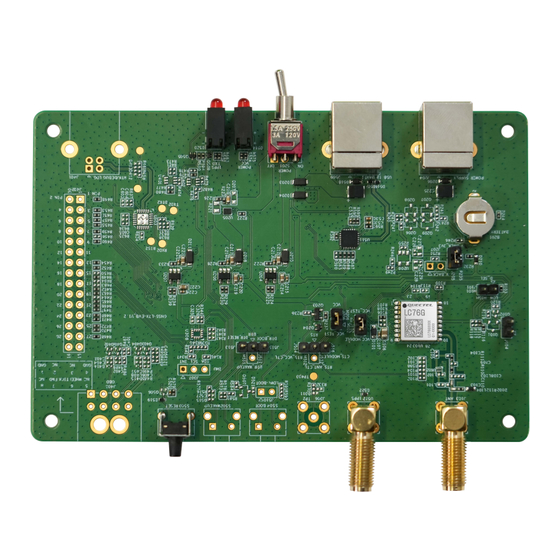
GNSS Module Series EVB Interfaces 3.1. EVB Top View EVB top view is shown in the figure below. D514 (POWER and VCC indication LEDs) S201 (Power switch) J509 (USB to UART) D520 (TXD and 1PPS indication LEDs) Test point 1 Test point 30 J402 (Test points) U103 (LC76G GNSS module) -
Page 14: Evb Interfaces
GNSS Module Series 3.2. EVB Interfaces The EVB interfaces are detailed in the table below. Table 3: Detailed EVB Interfaces Function Interfaces Description Power supply input: J509 Power Supply DC power supply: 4.5–5.5 V, Typ. 5.0 V USB to UART Current capability should be >... - Page 15 GNSS Module Series Table 4: J402 Pin Detailed Description Test Point No. Test Point Label Test Point Function Description PIN1 Ground U103: Pin 3 RXD: Receives data U103: Pin 5 Reserved U103: Pin 7 Reserved U103: Pin 9 RESET_N: Resets the module U103: Pin 11 NC (Not Connected) ANT_ON:...
- Page 16 GNSS Module Series Test Point No. Test Point Label Test Point Function Description U103: Pin 16 I2C_SDA: I2C serial data VDD_RF: Power supply U103: Pin 14 external RF components Ground Ground U103: Pin 8 VCC: Main power supply V_BCKP: Backup power supply U103: Pin 6 for backup domain of module U103: Pin 4...
-
Page 17: Test And Firmware Upgrade Via Qgnss Tool
GNSS Module Series Test and Firmware Upgrade via QGNSS Tool This chapter explains how to use the QGNSS software tool for verifying the status of GNSS module and for firmware upgrade. For more information about QGNSS use, see document [2] QGNSS user guide. -
Page 18: Qgnss Interface Explanation
GNSS Module Series Step 4: Click the “Connect or disconnect” button. The interface shown in the figure below appears once the module is connected. Figure 5: QGNSS Interface (Connected) 4.2. GNSS Interface Explanation You can view GNSS information, such as C/N message, time, position, speed, and precision in the QGNSS interface. - Page 19 GNSS Module Series Icon Explanation The sky view on the right shows the position of the satellites in use. GPS satellite BDS satellite GLONASS satellite Galileo satellite QZSS satellite NavIC satellite PRN 30 C/N is 39 dB-Hz. Column in bright red mean that the navigation data of the satellites ...
-
Page 20: Firmware Upgrading
GNSS Module Series 4.3. Firmware Upgrading Power on the EVB before upgrading the firmware, see for details. Chapter 4.1 Test via QGNSS Firmware upgrading steps: Step 1: Open QGNSS tool, and click “Tools” and select “Firmware Download” in the drop-down box. ①... - Page 21 GNSS Module Series ③ Figure 8: Firmware Selecting Step 4: Click the “Run” button and then short-press on the reset button after the progress bar prompts you to reset the module. ④ Figure 9: Firmware Upgrading Step 5: Upon successful firmware upgrading, the QGNSS tool’s progress bar on the screen will indicate “100 %”.
- Page 22 GNSS Module Series Figure 10: Successful Firmware Upgrading NOTE Make sure the module is in Continuous mode before upgrading firmware. LC76G_Series_EVB_User_Guide 21 / 33...
-
Page 23: Evb And Antenna Installation
GNSS Module Series EVB and Antenna Installation 5.1. GNSS Antenna Installation The installation environment affects antenna reception performance and satellite visibility, which in turn affect the positioning performance of a GNSS receiver. In addition, antenna’s position and direction can also impact its reception performance. Therefore, it is important to avoid obstacles and interference when installing antenna. -
Page 24: Measuring Power Consumption
GNSS Module Series Measuring Power Consumption 6.1. Power Consumption at Different Stages Module power consumption is measured in four stages: acquisition and tracking (including almanac update), tracking (almanac update is over), upon entering ALP mode and Backup mode. Acquisition and tracking (including almanac update): 0 s to 12.5 min ... -
Page 25: Power Consumption Measurement For Vcc Or In Alp Mode
GNSS Module Series 6.2. Power Consumption Measurement for VCC or in ALP Mode Before measuring the power consumption of VCC or in ALP mode, you must connect the components to the EVB to ensure that the module can communicate and fix it normally. See Chapter 4.1 Test via QGNSS. -
Page 26: V_Bckp Power Consumption Measurement
GNSS Module Series Power Consumption Meter Figure 13: Measured with Power Consumption Meter for VCC or in ALP Mode NOTE The EVB works normally. After entering the tracking mode, the module enters the ALP mode when the $PAIR732,1*21 command is sent. Then, the power consumption of the ALP mode can be measured. Record the average value when the power consumption in the ALP mode is stable. - Page 27 GNSS Module Series Ammeter Figure 14: Measured with Ammeter for LC76G (AB, PA) For LC76G (PB), pull out the V_BACK jumper cap (J207). Connect the ammeter in series to the pins of J207, as shown below. Ammeter Figure 15: Measured with Ammeter for LC76G (PB) Step 2: Switch on the power supply and read the ammeter.
- Page 28 GNSS Module Series For LC76G (AB, PA), pull out the V_BACK_3V3 jumper cap (J205). Then, ensure the positive pole of the power consumption meter is connected to pin 2 (with arrow silkscreen) of J205, and the negative pole is connected to GND. Power Consumption V_BCKP...
-
Page 29: Evb Framework
GNSS Module Series EVB Framework The power is supplied to EVB via Type-B, and then power to GNSS module via a Linear voltage regulator (LDO). GNSS module outputs the signals from communication interface on EVB via USB-to-UART Bridge Chip (CP2102N). There are an antenna interface and a control button on EVB. All functions of the module are available, including debugging. -
Page 30: Common Problems And Troubleshooting
Verify whether the module is in normal operating mode. Check that the downloaded firmware is correct. Confirm that the correct COM port has been selected. NOTE For the problem(s) that cannot be solved, please contact Quectel Technical Support (support@quectel.com). LC76G_Series_EVB_User_Guide 29 / 33... -
Page 31: Cautions
Ensure that the measurement method is correct. If there are significant differences between parameters tested via EVB and those provided by Quectel, please contact Quectel Technical Support. Note that momentary data obtained from measurement cannot always be regarded as reference data, ... -
Page 32: Appendix References
GNSS Module Series Appendix References Table 6: Related Documents Document Name Quectel_LC76G_Series_Hardware_Design [2] Quectel_QGNSS_User_Guide Quectel_LC26G&LC76G&LC86G_Series_GNSS_Protocol_Specification Table 7: Terms and Abbreviations Abbreviation Description 2 Dimension 3 Dimension BeiDou Navigation Satellite System Carrier-to-Noise Ratio Circular Error Probable COM Port Communication Port Direct Current Digital Input Digital Output ECEF... - Page 33 GNSS Module Series Abbreviation Description Galileo Galileo Satellite Navigation System (EU) GLONASS Global Navigation Satellite System (Russia) Ground GNSS Global Navigation Satellite System Global Positioning System HDOP Horizontal Dilution of Precision Inter-Integrated Circuit Input/Output NAVIC Indian Regional Navigation Satellite System Light Emitting Diode Longitude, Latitude, and Altitude Mean Sea Level...
- Page 34 GNSS Module Series Abbreviation Description SBAS Satellite-Based Augmentation System I2C Serial Data Standard Positioning Service TTFF Time to First Fix Transmit Data (Pin) UART Universal Asynchronous Receiver/Transmitter Universal Serial Bus Coordinated Universal Time WGS84 World Geodetic System 1984 LC76G_Series_EVB_User_Guide 33 / 33...
Need help?
Do you have a question about the LC76G Series and is the answer not in the manual?
Questions and answers