Advertisement
Quick Links
Advertisement

Related Manuals for Quectel LC29T (AA)


Summary of Contents for Quectel LC29T (AA)
- Page 1 LC29T (AA) EVB User Guide GNSS Module Series Version: 1.0 Date: 2024-09-20 Status: Released...
- Page 2 GNSS Module Series At Quectel, our aim is to provide timely and comprehensive services to our customers. If you require any assistance, please contact our headquarters: Quectel Wireless Solutions Co., Ltd. Building 5, Shanghai Business Park Phase III (Area B), No.1016 Tianlin Road, Minhang District, Shanghai...
- Page 3 Except as otherwise set forth herein, nothing in this document shall be construed as conferring any rights to use any trademark, trade name or name, abbreviation, or counterfeit product thereof owned by Quectel or any third party in advertising, publicity, or other aspects.
- Page 4 The following safety precautions must be observed during all phases of operation, such as usage, service or repair of any terminal incorporating Quectel LC76G series module. Manufacturers of the terminal should distribute the following safety precautions to users and operating personnel, and incorporate them into all manuals supplied with the product.
- Page 5 GNSS Module Series About the Document Document Information Title LC29T (AA) EVB User Guide Subtitle GNSS Module Series Document Type EVB User Guide Document Status Released Revision History Version Date Description 2022-12-07 Creation of the document 2024-09-20 First official release LC29T(AA)_EVB_User_Guide 4 / 33...
- Page 6 GNSS Module Series Contents Safety Information ............................3 About the Document ..........................4 Contents ..............................5 Table Index ..............................6 Figure Index ..............................7 Introduction ............................8 General Overview ..........................9 EVB Kit ............................9 2.1. Connect Cable and Antenna to EVB ..................10 2.2.
- Page 7 GNSS Module Series Table Index Table 1: List of Kit Components ........................9 Table 2: Detailed EVB Interfaces ....................... 13 Table 3: J401 Test Points ........................... 14 Table 4: QGNSS Interface Explanation...................... 18 Table 5: Related Documents ........................31 Table 6: Terms and Abbreviations ......................31 LC29T(AA)_EVB_User_Guide 6 / 33...
- Page 8 GNSS Module Series Figure Index Figure 1: EVB Kit Components ........................9 Figure 2: EVB and Components Assembly ....................10 Figure 3: EVB Top View ..........................12 Figure 4: COM Port and Baud Rate Setting ....................16 Figure 5: QGNSS Interface (Connected) ....................17 Figure 6: Testing 1PPS with GNSS Signal Simulator as the Reference ...........
- Page 9 GNSS Module Series Introduction This document provides information on the steps needed to evaluate the Quectel LC29T (AA) module using the Evaluation Board (EVB). The EVB is a convenient tool that allows you to become familiar with the LC29T (AA) module.
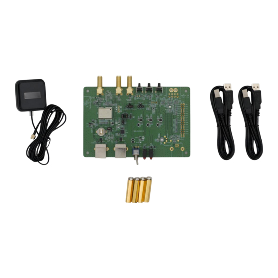
- Page 10 GNSS Module Series General Overview 2.1. EVB Kit The EVB kit includes: Evaluation Board (EVB), active GNSS antenna, Type-B USB cables, bolts and coupling nuts. The EVB kit contents are shown in the figure below. See Table 1: List of Kit Components for details.
- Page 11 Bolts and Coupling Nuts 4 pairs NOTE Request Quectel Technical Support (support@quectel.com) for details about Quectel Active GNSS Antenna. 2.2. Connect Cable and Antenna to EVB The connection between the EVB and its components is shown in the figure below.
- Page 12 GNSS Module Series NOTE The EVB can be powered by either “POWER SUPPLY” (J201) or “USB to UART” interface (J501). Thus, it is optional to connect PC and the “POWER SUPPLY” (J201) on the EVB via Type-B USB. Chapter 3.2 EVB Interfaces.
- Page 13 GNSS Module Series EVB Interfaces 3.1. EVB Top View EVB top view is shown in the figure below. S201 (Power switch) J501 (USB to UART) D501 (POWER and VCC indication LEDs) D507 (1PPS and TXD indication LEDs) J201 (POWER SUPPLY) Test point 16 Test point 15 EVB version...
- Page 14 GNSS Module Series 3.2. EVB Interfaces The EVB interfaces are detailed in the table below. Table 2: Detailed EVB Interfaces Function Interfaces Description J201 J201: Only used as power supply to avoid the POWER SUPPLY insufficient supply of J501. J501: Used for communication and power supply. Power Supply J501 Power supply input:...
- Page 15 GNSS Module Series The J401 test points of LC29T (AA) EVB are listed below: Table 3: J401 Test Points Test Point No. Test Point Label Test Point Function Description Ground CLK_OUT: Time pulse signal PIN1 U601: Pin 1 Reserved PIN2 U601: Pin 2 PIN3 U601: Pin 3...
- Page 16 GNSS Module Series Test Point No. Test Point Label Test Point Function Description VCC: Main power supply PIN23 U601: Pin 23 V_BCKP: Backup power supply PIN22 U601: Pin 22 for backup domain Ground Ground RXD: Receives data PIN21 U601: Pin 21 TXD: Transmits data PIN20 U601: Pin 20...
- Page 17 GNSS Module Series Test via QGNSS Tool This chapter explains how to use the QGNSS software tool for verifying the status of a GNSS module. For more information about QGNSS use, see document [3] QGNSS user guide. In addition, you can upgrade the module firmware via QGNSS tool, see document [4] firmware upgrade guide for details.
- Page 18 1. Ensure the CP210x driver has been installed when you use the QGNSS tool for the first time. For more information about driver, please contact Quectel Technical Support ( support@quectel.com ). 2. For more information on messages supported by the module, see document [5] protocol specification. LC29T(AA)_EVB_User_Guide 17 / 33...
- Page 19 GNSS Module Series 4.2. QGNSS Interface Explanation You can view GNSS information, such as C/N message, time, position, speed, and precision in the QGNSS interface. See the following table to find out more about these parameters. Table 4: QGNSS Interface Explanation Icon Explanation This sky view interface shows the position of the satellites in use.
- Page 20 GNSS Module Series Icon Explanation ⚫ Longitude (unit: °) (Decimal Degrees) ⚫ Latitude (unit: °) (Decimal Degrees) ⚫ Altitude (MSL) (Unit: m) ⚫ Altitude (EPH) (Unit: m) ⚫ Receiver speed (Unit: km/h) ⚫ Horizontal dilution of precision ⚫ Position dilution of precision ⚫...
- Page 21 PC to calculate the delay error. You can use your equipment instead of the GNSS Signal Simulator or the Rubidium Clock to achieve the appropriate functionality. NOTE 1. For test result comparison, verify the firmware version used. Contact Quectel Technical Support (support@quectel.com) or see document [5] protocol specification for details on the related firmware version.
- Page 22 GNSS Module Series GNSS Signal Standard Simulator 1PPS Signal Oscilloscope test cable and probe Oscilloscope GNSS Signal RF cable Antenna Connector (J101) Oscilloscope test cable and probe 1PPS Connector LC29T (AA) EVB (J510) USB to UART (with Plugins) (J501) Type-B USB cable Collect waveform data, calculate and compare the delay error Figure 6: Testing 1PPS with GNSS Signal Simulator as the Reference...
- Page 23 GNSS Module Series Active GNSS Antenna Oscilloscope test Rubidium cable and probe Power GNSS Standard Signal Divider 1PPS Signal Clock Oscilloscope Antenna Connector (J101) 1PPS Oscilloscope test cable and probe LC29T (AA) EVB Connector (J510) Type-B USB cable USB to UART (with Plugins) (J501)...
- Page 24 GNSS Module Series EVB and Antenna Installation 6.1. GNSS Antenna Installation The installation environment affects antenna reception performance and satellite visibility, which in turn affect the positioning performance of a GNSS receiver. In addition, antenna’s position and direction also impact its reception performance. Therefore, it is important to avoid obstacles and interference when installing antennas.
- Page 25 GNSS Module Series Measuring Power Consumption 7.1. Power Consumption at Different Stages Module power consumption is measured in three stages: acquisition and tracking (including almanac update), tracking (almanac update is over) and upon entering Backup mode. ⚫ Acquisition and tracking (including almanac update): 0 s to 12.5 min ⚫...
- Page 26 GNSS Module Series Ammeter Figure 9: VCC Power Consumption Measured with Ammeter Detailed steps for measuring VCC power consumption with a power consumption meter: Step 1: Switch off the power supply (S201) of the module and pull out the VCC_MODULE jumper cap (J601).
- Page 27 GNSS Module Series 7.3. V_BCKP Power Consumption Measurement Before measuring the V_BCKP power consumption, you must connect the components to EVB to ensure that the module can communicate and fix normally. See Chapter 4.1 Test via QGNSS. Detailed steps for measuring V_BCKP power consumption with an ammeter: Step 1: Switch off the power supply (S201) of the module and pull out the V_BACK jumper cap (J202).
- Page 28 GNSS Module Series Power Consumption Meter V_BCKP Figure 12: V_BCKP Power Consumption Measured with Power Consumption Meter NOTE Adjust the current resolution when using the power consumption meter. Formula for calculating the power value: P = V ×I Supply Test When measuring the V_BCKP power consumption in Backup mode, ensure that the module has entered Backup mode, and then remove the jumper cap of VCC_MODULE (J601) to cut off the power supply of VCC.
- Page 29 GNSS Module Series EVB Framework The power is supplied to EVB via a Type-B USB cable, and then to the GNSS module via a Low-dropout Regulator (LDO). GNSS module outputs the signals from the communication interface on EVB via USB to UART Bridge Chip (CP2102N).
- Page 30 Verify whether the module is in BOOT download mode or normal operating mode. ⚫ Check that the downloaded firmware is correct. ⚫ Confirm that the correct COM port has been selected. NOTE For the issue(s) that cannot be solved, you can contact Quectel Technical Support (support@quectel.com). LC29T(AA)_EVB_User_Guide 29 / 33...
- Page 31 ⚫ Ensure that the measurement method is correct. If there are significant differences between parameters tested via EVB and those provided by Quectel, please contact Quectel Technical Support. ⚫ Note that momentary data obtained from measurement cannot always be regarded as reference data, because it may be affected by various factors, such as satellite positions at different times, environmental conditions, temperature, humidity and altitude.
- Page 32 GNSS Module Series Appendix References Table 5: Related Documents Document Name Quectel_LC29T(AA)_Hardware_Design [2] Quectel_LC29T(AA)_Reference_Design Quectel_QGNSS_User_Guide Quectel_LG69T(AA,AD,AF,AI,AJ,AR)&LC29T(AA)&LC99T(IA)_Firmware_Upgrade_Guide Quectel_LC29T(AA)&LC99T(IA)_GNSS_Protocol_Specification Quectel_GNSS_Antenna_Application_Note Table 6: Terms and Abbreviations Abbreviation Description 1PPS One Pulse Per Second 2 Dimension 3 Dimension BeiDou Navigation Satellite System Carrier-to-noise Ratio COM Port Communication Port Direct Current...
- Page 33 GNSS Module Series Abbreviation Description Ellipsoidal Height Electrostatic Discharge Evaluation Board Galileo Galileo Satellite Navigation System (EU) GLONASS Global Navigation Satellite System (Russia) Ground GNSS Global Navigation Satellite System Global Positioning System Inter-integrated Circuit Input/Output NavIC (IRNSS) Indian Regional Navigation Satellite System Light Emitting Diode Mean Sea Level NMEA...
- Page 34 GNSS Module Series Abbreviation Description SubMiniature Version A Standard Positioning Service TTFF Time to First Fix Transmit Data (Pin) UART Universal Asynchronous Receiver/Transmitter Universal Serial Bus Coordinated Universal Time LC29T(AA)_EVB_User_Guide 33 / 33...
Need help?
Do you have a question about the LC29T (AA) and is the answer not in the manual?
Questions and answers