Table of Contents
Advertisement
Quick Links
Bus node
CPX-FB37
Brief description
Original: de
Bus node CPX-FB37
. . . . . . . . . . . . . . . . . . . . . . . . . . . . . . . . . . . . . . . . . . . .
®
®
EtherCAT
and TORX
are registered trademarks of the respective trade-
mark owners in certain countries.
1
Intended use
The bus node CPX-FB37 is intended exclusively for use in CPX terminals, as a parti-
cipant in the EtherCAT network and as follows:
– in excellent technical condition
– in original status, without unauthorised modifications
– within the limits of the product defined through the technical data
– in an industrial environment.
You can find detailed information in the bus node description
(P.BE-CPX-FB37-...) and in the CPX system description (P.BE-CPX-SYS-...).
You can receive information on EtherCAT in the Internet:
EtherCAT Technology Group
2
Target group
The target group of this documentation consists of trained specialists in control
and automation technology.
3
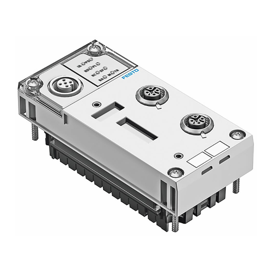
Connection and display components
6
5
4
1
EtherCAT-specific network status
LEDs and CPX-specific LEDs
2
Network connection 1
(input "X.1 In")
3
Network connection 2
(output "X2 Out")
Fig. 1
Festo AG & Co. KG
Postfach
73726 Esslingen
Germany
+49 711 347-0
www.festo.com
8029653
1406NH
[8029655]
www.ethercat.org.
1
2
3
4
Cover for DIL switches
5
Service interface for operator unit
(CPX-MMI) and USB adapter for
CPX-FMT
6
Rating plate
3.1 Network connections
There are two 4-pin M12 sockets (D-coded) on the bus node for connection of the
bus node to the EtherCAT network.
M12 socket,
Pin
D-coded
1
2
3
4
Housing
Fig. 2
3.2 LED displays
Behaviour of the LED indicators in normal operating status:
– The LEDs "Run", "PS" and "PL" are illuminated.
– The LEDs "LA/X1" and "LA/X2" are illuminated or flash if the assigned network
connection is used.
– The LEDs "Error" and "SF" are not illuminated.
– The LED "M" is illuminated with the setting "System start with saved
parameters".
– The LED "M" flashes if "Force" is active.
EtherCAT network status LEDs
Run (green)
Operating status
English
Error (red)
EtherCAT error
LA/X1 (green) Connection status X1 In/
X2 Out
LA/X2 (green)
1) Detailed information:
2) Network connection or data traffic at "X1 In" or "X2 Out"
3) Flashes in case of error, diagnostics by means of error number:
(P.BE-CPX-SYS-...)
4) "System start with saved parameters" or "forcing" active
Fig. 3
4
Mounting/dismounting
Warning
Danger of injury to people, damage to the machine and system resulting from
uncontrolled movements of the actuators and undefined switching states
• Switch off the operation and load voltage supplies.
• Switch off the compressed air supply.
• Exhaust the valve terminal pneumatics.
Warning
Danger of electric shock
• For the electrical power supply, use only PELV circuits in accordance with
IEC/EN 60204-1 (Protective Extra-Low Voltage, PELV).
• Observe the general requirements of IEC/EN 60204-1 for PELV circuits.
• Only use voltage sources that ensure a reliable electric separation of operat-
ing voltage in accordance with IEC/EN 60204-1.
Note
Damage to the electronics
The bus node includes electrostatically sensitive devices.
• Do not touch any components.
• Observe the handling specifications for electrostatically sensitive devices.
Note
• Only commission a CPX terminal which has been completely mounted and
connected.
• Observe the specifications in the CPX system description, in the descriptions
of the valve terminal used as well as in the assembly instructions of the indi-
vidual components.
Signal
TD+
RD+
TD–
RD–
FE
1)
CPX-specific LEDs
PS (green)
PL (green)
SF (red)
2)
M (yellow)
bus node description (P.BE-CPX-FB37-...)
Explanation
Transmitted data (Transmit Data) +
Received data (Receive Data) +
Transmitted data –
Received data –
Screening/functional earth
1)
Power system
Power Load
3)
System Failure
4)
Modify
CPX system description
Advertisement
Table of Contents

Related Manuals for Festo CPX-FB37


Summary of Contents for Festo CPX-FB37
- Page 1 Intended use 3) Flashes in case of error, diagnostics by means of error number: CPX system description The bus node CPX-FB37 is intended exclusively for use in CPX terminals, as a parti- (P.BE-CPX-SYS-...) cipant in the EtherCAT network and as follows: 4) “System start with saved parameters”...
- Page 2 When built-in, the bus node is located in an interlinking block of the CPX terminal. 5.2 Setting the operating mode with DIL switch 1 You can set the operating mode of the bus node with switch element 1.1 of DIL switch 1.
- Page 3 Parameterisation The CPX terminal and the related bus node can be parameterised by means of the Festo operator unit (CPX-MMI), Festo Maintenance Tool (CPX-FMT) or EtherCAT (CoE). The CPX modules are made available in the configuration file (ESI file). You can find the current configuration files (ESI files) and additional in- formation on the Festo Internet page in the Support Portal /sp).
Need help?
Do you have a question about the CPX-FB37 and is the answer not in the manual?
Questions and answers