Sign In
Upload
Manuals
Brands
LSIS Manuals
Controller
XBF-DC04A
LSIS XBF-DC04A Analog Expansion Module Manuals
Manuals and User Guides for LSIS XBF-DC04A Analog Expansion Module. We have
2
LSIS XBF-DC04A Analog Expansion Module manuals available for free PDF download: User Manual
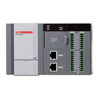
LSIS XBF-DC04A User Manual (1284 pages)
Ultimate Performance XGB Unit
Brand:
LSIS
| Category:
Controller
| Size: 37 MB
Table of Contents
Table of Contents
9
Chapter 1 Introduction
17
Guide to Use this Manual
17
Part1. System
17
Features
19
Terminology
21
Chapter 2 System Configuration
34
Table of Products Configuration
34
Classification and Type of Product Name
36
High Performance Xgb's System Configuration
40
Chapter 3 Specifications
46
Names and Functions of each Part
46
General Specifications
51
Power Specifications
52
Battery
55
Performance Specifications
57
Chapter 4 Installation and Wiring
61
Parameter & Operation Data
61
Attachment/Detachment of Modules
67
Wire
73
Chapter 5 Maintenance
79
Maintenance and Inspection
79
Daily Inspection
80
Periodic Inspection
80
Basic Procedure of Troubleshooting
81
Chapter 6 Troubleshooting
81
Troubleshooting
81
Troubleshooting Questionnaire
87
Troubleshooting Examples
88
Error Code List
92
Chapter 7 EMC Standard
94
Requirements for Conformance to EMC Directive
94
Requirement to Conform to the Low-Voltage Directive
97
Chapter 1 Program Configuration and Operation Method
98
Part2. Basic Functions
98
Programming Basics
98
Operation Mode
120
Memory
123
Chapter 2 CPU Function
127
Type Setting
127
Parameter Setting
128
Self-Diagnosis Function
131
RTC Function
139
Remote Functions
141
I/O Forced On/Off Functions
142
Direct I/O Operation Function
143
Function Saving the Operation History
145
How to Allocate I/O no
146
Program Modification During Operation (Modification During RUN)
147
Read I/O Information
150
Function to Delete All of the PLC
156
Chapter 3 Input/Output Specifications
157
Introduction
157
Main Unit Digital Input Specifications
164
Main Unit Digital Output Specifications
165
Digital Input Specifications
167
Digital Output Specifications
170
Combined Digital I/O Module Input Specification
179
Combined Digital I/O Module Output Specification
180
I/O Modules' Functions
181
Chapter 4 Built-In High-Speed Counter Function
185
High-Speed Counter Specifications
185
Installation and Wiring
205
Internal Memory
206
Example of Using High-Speed Counter
210
Chapter 5 Data Log Function
214
Overview
214
Performance Specifications
219
Specific Functions
221
Regular Save
238
Trigger Save
244
Event Save
265
Additional Functions
287
CSV File Structure
293
SD Memory Card
295
Flag List
301
Data Processing Time
305
Chapter 6 Built-In PID Function
310
Features of Built-In PID Function
310
Basic Theory of PID Control
311
Functional Specifications of PID Control
318
Usage of PID Control Functions
319
PID Instructions
335
PID Auto-Tuning
338
Example Programs
347
Error / Warning Codes
358
Chapter 1 Overview
360
Characteristics
360
Part3. Embedded Positioning
360
Purpose of Positioning Control
362
Signal Flow of Embedded Positioning
363
Function Overview of Embedded Positioning
364
Chapter 2 Specifications
372
External Interface I/O Specifications
374
The Name of each Part
379
Chapter 3 Operation Order and Installation
380
Operation Order
380
Installation
381
Notices in Wiring
382
Chapter 4 Positioning Parameter & Operation Data
400
Parameter & Operation Data
400
Basic Parameter
401
Extended Parameter
406
Manual Operation Parameter
418
Homing Parameter
419
I/O Signal Parameter
423
Common Parameter
424
Operation Data
428
Chapter 5 Internal Memory and I/O Signal
433
Internal Memory
433
I/O Signal
441
Chapter 6 Function Block
444
Common Items of Function Blocks
444
Positioning Module Function Block
446
Function Blocks Related to Reading Module Information
448
Function Blocks Related to Parameters/Changing Operating Data
452
Function Blocks Related to Start-Up and Stop
468
Function Blocks Related to Manual Operation
477
Function Block Related to Synchronous Operation
480
Function Blocks Related to Changes
485
Function Blocks Related Errors
497
Chapter 7 Program
505
Example of Programming
505
Chapter 8 Functions
554
Homing
561
Positioning Control
564
Manual Operation Control
653
Synchronous Control
660
Modification Function of Control
679
Auxiliary Function of Control
697
Data Modification Function
703
Chapter 9 Positioning Error Information & Solutions
715
Positioning Error Information & Solutions
715
Chapter 10 Internal Memory Address of "Read/Write Variable Data" Command
731
Parameter Memory Address
731
Axis 1 Operation Data Memory Address
735
Axis 2 Operation Data Memory Address
744
Axis 3 Operation Data Memory Address
753
Axis 4 Operation Data Memory Address
762
CAM Data Memory Address
771
User CAM Data Memory Address
821
Advertisement
LSIS XBF-DC04A User Manual (618 pages)
Analog Programmable Logic Controller
Brand:
LSIS
| Category:
Controller
| Size: 12 MB
Table of Contents
Table of Contents
12
Analog Product List
18
Specification of Analog Module
20
Setting Sequence before Operation
35
Specifications
36
Name of Part and Function
38
Characteristic of I/O Conversion
39
Conversion Characteristic According to Input Range
40
Accuracy
43
Functions of Analog Input Module
44
Wiring
47
Operation Parameter Setting
51
Special Module Monitoring Functions
53
Register U Devices
58
Configuration and Function of Internal Memory
62
Example Program
68
Troubleshooting
74
Setting Sequence before Operation
78
Specification
79
Designations and Functions
81
Characteristic of I/O Conversion
82
Characteristic of Input/Output
83
Accuracy
84
Functions of Analog Output Module
85
Wiring
86
Operation Parameter Setting
88
Special Module Monitoring Function
90
Register U Devices
93
Internal Memory
97
Example Program
102
Troubleshooting
105
Setting Sequence before Operation
108
Specifications
109
Part Names and Functions
111
Temperature Conversion Characteristic
112
Conversion Speed
113
Scaling Function
114
Disconnection Detection Function
115
Wiring
116
Filtering Function
118
Operation Parameter Setting
119
Special Module Monitoring
122
Register U Devices
125
Configuration and Function of Internal Memory
128
Example Program
132
Troubleshooting
135
General
138
Specification
141
Name of Part and Function
144
Function
151
Average Function
154
Installation and Wiring
156
Operation Parameter Setting
159
Special Module Monitoring Functions
164
Register U Devices
168
Configuration and Function of Internal Memory
173
Example Program
188
Troubleshooting
193
Pre-Operation Setting Procedure
198
Specification
199
Major Components
202
Conversion Characteristics by I/O Range
203
Precision
207
Functions of Analog I/O Module
209
Wiring
215
Operation Parameter Setting
219
Special Module Monitor Function
221
Auto-Registration of U-Device (Special Module Variable)
225
Constitution and Function of Internal Memory
230
Example Program
237
Troubleshooting
243
Setting Sequence before Operation
285
Specifications
286
Name of Part and Function
288
Characteristic of I/O Conversion
289
Accuracy
291
Functions of Analog Input Option Board
292
Wiring
295
Operation Parameter Setting
297
Special Module Monitoring Functions
300
Register U Devices
304
Configuration and Function of Internal Memory
310
Example Program
318
Troubleshooting
320
Setting Sequence before Operation
353
Specifications
354
Name of Part and Function
357
Characteristic of I/O Conversion
358
Accuracy
362
Wiring
368
Operation Parameter Setting
372
Special Module Monitoring Functions
374
Register U Devices
378
Configuration and Function of Internal Memory
384
Example Program
394
Troubleshooting
397
Setting Sequence before Operation
426
Specifications
427
Characteristic of Thermocouple Temperature Conversion
430
Accuracy
431
Conversion Speed
432
Function
433
Operation Setting and Monitor
437
Configuration and Function of Internal Memory
449
Example Program
456
Troubleshooting
460
Setting Sequence before Operation
462
Specifications
463
Name of each Part and Functions
466
Characteristic of I/O Conversion
467
Accuracy
469
Functions of Analog Input Module
470
Installation and Wiring
477
Operation Parameter Setting
483
Special Module Monitoring Functions
486
Register U Devices
490
Configuration and Function of Internal Memory
497
Example Program
504
Breakdown Test
506
Setting Sequence before Operation
509
Specifications
510
Name of each Part and Functions
513
Conversion Characteristic of each Output Range
514
Accuracy
517
Functions of Analog Output Module
518
Installation and Wiring
522
Operation Parameter Setting
526
Special Module Monitoring Functions
529
Register U Devices
532
Internal Memory
536
Example Program
544
Breakdown Test
547
General
550
PID Control
552
PID Instructions
576
PID Auto-Tuning
582
Example Programs
591
Error/Warning Codes
603
Advertisement
Related Products
LSIS XBF-DV04A
LSIS XBF-DC04C
LSIS XBF-DV04C
LSIS XBF-AD08A
LSIS XBF-AD04A
LSIS XBF-TC04S
LSIS XBF-RD04A
LSIS XBF-AH04A
LSIS XBF-AD04C
LSIS XBE-RY08B
LSIS Categories
Controller
Inverter
Control Unit
DC Drives
Relays
More LSIS Manuals
Login
Sign In
OR
Sign in with Facebook
Sign in with Google
Upload manual
Upload from disk
Upload from URL