
Related Manuals for Magnetek Enrange Flex EX


Summary of Contents for Magnetek Enrange Flex EX
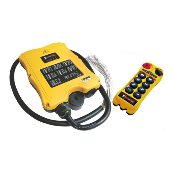
- Page 1 Flex 8EX EU System Radio Control Equipment Instruction Manual 191-00193-0003–R0 March 2012 © Copyright 2012 Magnetek Material Handling...
- Page 2 Service Information Your New Radio System Thank you for your purchase of Magnetek’s Enrange™ Flex EX radio remote control system. Without a doubt, our Flex EX system is the ultimate solution for providing precise, undeterred, and safe control of your material.
-
Page 3: Table Of Contents
Table of Contents 1. Introduction ............................. 2 2. Radio Controlled Safety ......................... 3 3. General System Information ........................4 A. Transmitter Handset ..........................4 1. External Illustration (Standard Push Button Configuration) ............... 4 2. Internal Illustration ..........................5 ... -
Page 4: Introduction
1. Introduction The Flex radio remote control systems are designed for control of industrial equipment and machinery such as overhead traveling cranes, jib cranes, gantry cranes, tower cranes, electric hoists, winches, monorails, conveyor belts, mining equipment and other material handling equipment where wireless control is preferred. -
Page 5: Radio Controlled Safety
2. Radio Controlled Safety Flex radio remote control systems should be operated by persons with a sufficient amount of knowledge and skill in crane operation and safety. Persons being trained to operate a radio remote controlled crane should possess the knowledge of all hazards peculiar to radio remote controlled crane operation, ability to judge distance and moving objects, equipment capacity and radio remote controlled safety rules. -
Page 6: General System Information
3. General System Information A. Transmitter Handset 1. External Illustration (Standard Push Button Configuration) (Fig. 01) (Fig. 02) Emergency Stop Button Push Button #5 Removable Power Key Switch Push Button #7 Push Button #2 Strap Ring Push Button #4 System Information Push Button #6 System Channel Push Button #8... -
Page 7: Internal Illustration
2. Internal Illustration (Fig. 03) (Fig. 04) Encoder Board I-CHIP Arial Antenna Function Dip-Switch Transmitting Module Channel Dip-Switch Status LED Display Battery Contact Mechanism Function LED Displays Flex 8EX EU System Instruction Manual March 2012 5 of 37... -
Page 8: Receiver Unit
B. Receiver Unit 1. External Illustration (Fig. 05) Shock Mount COM LED Display Optional External Antenna (BNC) Jack Output Contact Diagram Power LED Display System Information Status LED Display Cord Grip SQ LED Display Flex 8EX EU System Instruction Manual March 2012 6 of 37... -
Page 9: Internal Illustration
2. Internal Illustration (Fig. 06) AC Line Filter Decoder Module Power Transformer Output Relay Board Receiving Module Flex 8EX EU System Instruction Manual March 2012 7 of 37... -
Page 10: Function Settings
4. Function Settings A. Transmitter Handset 1. System Channel Settings CHANNEL (Fig. 07) Set the transmitter channel by adjusting the channel dip-switch located on the backside of the transmitter encoder board (refer to Fig. 07 above). Only the first six (6) positions are used for channel programming (refer to Fig. -
Page 11: Continuous Transmitting Time Adjustment
2. Continuous Transmitting Time Adjustment After the push button is released the transmitter will continue to transmit neutral signals to the receiver for up (Type 1) to one (1) minute. After one (1) minute the transmitter will cease transmission thus temporarily disconnecting the receiver MAIN. -
Page 12: Push Button Functions With Led Displays
3. Push Button Functions with LED Displays a. Standard Push Button Configuration (Transmitter Toggle) Set the transmitter toggle (latching output relay) function by adjusting the 8-position function dip-switch located on the backside of the transmitter encoder board (refer to Fig. 09 below). - Page 13 b. Standard Push Button Configuration (A/B Selector) There are four (4) different types of A/B selector sequences available on the Flex system. Choose the one that is most suitable for your application. Type-A selector sequence A+B → A → B → A+B … Type-B selector sequence Off →...
- Page 14 c. Inline Push Button Configuration (Transmitter Toggle) The push button arrangement for inline push button setup starts from top to bottom and then from the right column to the left column (refer to Fig. 10 below). To set the inline push button configuration, please refer to JP4 and JP5 jumpers setting on page 24.
- Page 15 d. Inline Push Button Configuration (A/B Selector) There are four (4) different types of A/B selector sequences available on the Flex system. Choose the one that is most suitable for your application. Type-A selector sequence A+B → A → B → A+B … Type-B selector sequence Off →...
-
Page 16: Channel Change Via Push Buttons
4. Channel Change via Push Buttons Other than the CHANNEL dip-switch on the encoder board, the transmitter channel can also be changed directly on the push buttons. Please refer to the instructions below on how to change the transmitter channel via push buttons. Press and hold PB1, PB2 and PB3 and rotate the power key to START position at the same time. -
Page 17: Optional 4-Digit Security Code
5. Optional 4-Digit Security Code The 4-digit Security Code is an optional feature that can be programmed into the transmitter to allow operation only to those who know the code. If this feature is desired, set up as follows: Prior to rotating the transmitter power key-switch to START position to begin operation, you first enter a 4-digit security code in order to proceed further. -
Page 18: I-Chip
6. I-CHIP The I-CHIP functions in a way that is very similar to a SIM card inside a mobile phone, which stores system information such as your telephone number, account number, phone book and other settings. The I-CHIP works exactly the same way, as it stores information such as system serial number/ID codes, channel configurations and push button configurations. -
Page 19: Receiver Unit
B. Receiver Unit 1. System Channel Settings (Fig. 12) Even though the Flex system is equipped with an automatic channel scanning receiver, the user can also set the receiver channel manually. Please refer to page 32 on how the automatic channel scanning receiver works. -
Page 20: Output Relay Configurations
2. Output Relay Configurations a. Output Relay Types Three (3) output relays per motion – shared 2 speed output relay Output relays with Forward 1 speed (F1), Reverse 1 speed (R1) and Forward/Reverse 2 speed (F/R2). Forward and Reverse 2 speed (F/R2) share the same output relay. - Page 21 4-output relays configuration with Opened/Closed contact at 2 speed At 2 speed, only the 2 speed (F2 or R2) output relay is closed (refer to page 22 on how to set to this function). Forward 1 speed push button pressed Forward 2 speed push button pressed ↓...
- Page 22 e. Magnet ON/OFF Push Button Function The user can set any of the two adjacent push buttons on the transmitter to control a magnet. To activate the magnet just press the push button with the Magnet symbol. To deactivate the magnet, for safety purpose, you must first press and hold the Magnet push button and then press the OFF push button.
-
Page 23: Receiver Auto-Scanning Settings
k. Pitch & Catch Function This function allows two operators to control one crane from opposite ends of a cross or long travel (refer to page 23 on how to set to this function). When set to “Pitch & Catch,” make sure the 2 transmitter is set to the next upper channel (channel X*+1). -
Page 24: Dip-Switch Settings
4. Dip-Switch Settings a. Interlocked Functions Interlocked means the two adjacent push buttons can not be activated simultaneously as they will cancel each other out. Interlocked settings are usually applied to a crane’s forward and reverse motions. Each dip-switch on the decoder module corresponds to one (1) motion or two (2) adjacent push buttons (refer to Fig. - Page 25 b. Non-Interlocked Functions Contrary to interlocked settings, non-interlocked settings allow the two adjacent push buttons be used simultaneously. Non-interlocked settings are usually applied to a crane’s auxiliary functions such as lights, horns, 3 speed, auxiliary stops and Pitch & Catch. Each dip-switch on the decoder module corresponds to one (1) motion or two (2) adjacent push buttons (left &...
-
Page 26: Jumper Settings
5. Jumper Settings Jumper settings are applied to functions such as mainline-disconnect time, Start function, transmitter push button layout, system information (serial number/ID code) programming and system testing. The jumpers #1- #7 are located on the decoder module above the four (4) dip- switches (refer to Fig.16 below). -
Page 27: I-Chip Programming Port
6. I-CHIP Programming Port (Fig. 17) The I-CHIP programming port located on the decoder module (refer to Fig. 17 above) inside the receiver is designed for the purpose of transferring system serial number/ID code either from the I-CHIP to the receiver or vice versa. If you wish to transfer system information from the receiver to the I-CHIP, just insert the I-CHIP onto the programming port (JP6 jumper not inserted), wait until the Status LED on the decoder module turns a constant green (within 2 seconds), and then take the I-CHIP out of the programming port (programming completed). -
Page 28: System Channels Table
5. System Channels Table Dip-switch Dip-switch Frequency Frequency Channel Channel Setting Setting 433.000MHZ 000000 433.775MHZ 100000 433.000MHZ 000001 433.800MHZ 100001 433.025MHZ 000010 433.825MHZ 100010 433.050MHZ 000011 433.850MHZ 100011 433.075MHZ 000100 433.875MHZ 100100 433.100MHZ 000101 433.900MHZ 100101 433.125MHZ 000110 433.925MHZ 100110 433.150MHZ 000111 433.950MHZ... -
Page 29: Receiver Installation
6. Receiver Installation A. Output Relay Contact Diagram For the 3-relay (shared 2 speed) and 4-relay (separate 2 speed) configuration please refer to pages 18-22. For the 4-relay closed/closed and 4-relay opened/closed relay configuration please refer to pages 18-22. For different voltage settings please refer to page 25. For F9 and F10 power fuse ratings please refer to page 25. -
Page 30: Pre-Installation Precautions
B. Pre-Installation Precautions 1. Make sure the transmitter and the receiver have identical serial number/ID codes and channels. 2. Make sure the receiver is not set to the same channel as any other systems in use in the surrounding area. 3. -
Page 31: System Testing
Ensure the selected location has adequate space to accommodate the receiver (refer to Fig. 19 on page 28). If an external antenna is used, always locate the receiver where the antenna is free from any obstacles from all directions to avoid possibility of antenna damage (refer to diagram at right). -
Page 32: Operating Procedure
7. Operating Procedure A. Transmitter Operation 1. General Operating Procedure Reset the red emergency stop button located on the top left hand side of the transmitter handset by rotating it either clockwise or counter clockwise. The red button will pop up. Turn on the transmitter power by inserting the black-colored key into the power key slot (located on the top right hand side of the transmitter handset) and rotate it clockwise to the “On”... -
Page 33: A/B Selector Push Button Operating Procedure
In case of an emergency, pressing down the red emergency stop button will immediately disconnect the receiver MAIN and as well as the transmitter power. To resume operation, rotate the red button clockwise or counter clockwise, it will pop up. Then rotate the power key-switch to START position for up to 1.0 second to activate all transmitter push button functions and the receiver MAIN. -
Page 34: Pitch & Catch Operating Procedure
4. Pitch & Catch Operating Procedure To release control of the crane, press the “Pitch” push button. To take over control of the crane, rotate the power key switch to the “Catch” position for up to 2 seconds. The second operator cannot take control of the crane unless the first operator presses the “Pitch”... -
Page 35: Status Light Indicators & Warnings
B. Status Light Indicators & Warnings 1. Transmitter STATUS Light Indication Type Display Type Indication Voltage below 1.9V at initial power on, transmitter power and receiver MAIN shuts off. Constant red Voltage below 1.8V during operation, transmitter power and receiver MAIN shuts off. 1 red blink followed by a 2- Voltage goes below 1.85V during operation - second pause... -
Page 36: Receiver Status Light Indication
2. Receiver STATUS Light Indication Type Display Type Indication Fast green blinks Decoding in process Slow green blinks Decoding on standby Two red blinks Receiver MAIN is jammed or defective Fast red blinks Incorrect transmitter serial number/ID code Receiver under-voltage, LV output relay Constant red activated No light displayed... -
Page 37: Troubleshooting Tips
C. Troubleshooting Tips Problems Possible Reasons Suggestions Transmitter low battery power Check the transmitter battery level. Prior to turning on the transmitter power switch Emergency stop button make sure that the red emergency stop button activated prior to startup is elevated. Transmitter push button Initiate the Start command by rotating the functions locked... -
Page 38: System Specifications
8. System Specifications Frequency Range 433 - 434 MHz Frequency Deviation 12.5 KHz Number of Channels 62 channels Modulation Digital Frequency Modulation based on Manchester Code, 20bit address, 32bit CRC Parity Check and Hamming Code. Encoder & Decoder Microprocessor-controlled Transmitting Range >100 Meters / 300 Feet Frequency Control Synthesized PLL (Phase Lock Loop) - Page 39 Flex 8EX EU System Instruction Manual March 2012 37 of 37...
Need help?
Do you have a question about the Enrange Flex EX and is the answer not in the manual?
Questions and answers